EP1557513A1 - Schloss mit zurückziehbarer Falle - Google Patents
Schloss mit zurückziehbarer Falle Download PDFInfo
- Publication number
- EP1557513A1 EP1557513A1 EP05100233A EP05100233A EP1557513A1 EP 1557513 A1 EP1557513 A1 EP 1557513A1 EP 05100233 A EP05100233 A EP 05100233A EP 05100233 A EP05100233 A EP 05100233A EP 1557513 A1 EP1557513 A1 EP 1557513A1
- Authority
- EP
- European Patent Office
- Prior art keywords
- lock
- particular according
- lock according
- spring element
- stop
- Prior art date
- Legal status (The legal status is an assumption and is not a legal conclusion. Google has not performed a legal analysis and makes no representation as to the accuracy of the status listed.)
- Granted
Links
- 230000000630 rising effect Effects 0.000 claims abstract description 4
- 230000008859 change Effects 0.000 claims description 13
- 230000002401 inhibitory effect Effects 0.000 claims description 3
- 238000006073 displacement reaction Methods 0.000 description 6
- 230000002093 peripheral effect Effects 0.000 description 4
- 238000009434 installation Methods 0.000 description 3
- 230000009467 reduction Effects 0.000 description 3
- 230000003993 interaction Effects 0.000 description 2
- 238000004519 manufacturing process Methods 0.000 description 2
- 230000002829 reductive effect Effects 0.000 description 2
- 238000010276 construction Methods 0.000 description 1
- 230000008878 coupling Effects 0.000 description 1
- 238000010168 coupling process Methods 0.000 description 1
- 238000005859 coupling reaction Methods 0.000 description 1
- 230000036961 partial effect Effects 0.000 description 1
- 230000000717 retained effect Effects 0.000 description 1
- 230000001960 triggered effect Effects 0.000 description 1
Images


Classifications
-
- E—FIXED CONSTRUCTIONS
- E05—LOCKS; KEYS; WINDOW OR DOOR FITTINGS; SAFES
- E05B—LOCKS; ACCESSORIES THEREFOR; HANDCUFFS
- E05B63/00—Locks or fastenings with special structural characteristics
-
- E—FIXED CONSTRUCTIONS
- E05—LOCKS; KEYS; WINDOW OR DOOR FITTINGS; SAFES
- E05B—LOCKS; ACCESSORIES THEREFOR; HANDCUFFS
- E05B63/00—Locks or fastenings with special structural characteristics
- E05B63/04—Locks or fastenings with special structural characteristics for alternative use on the right-hand or left-hand side of wings
- E05B63/044—Locks or fastenings with special structural characteristics for alternative use on the right-hand or left-hand side of wings with reversible bolt or bolt head
Definitions
- the invention relates to a lock with a by turning a follower or retractable by pressing a change lever latch, wherein the Change lever a rising, controlled by the closing member longitudinal section and one hinged thereto at a pivot point, about a pivot axis pivotable portion, wherein the pivotable portion on the tail tail attacks.
- the object of the invention is the object of a generic Castle in such a way that, while largely retaining his Advantageous structure installation tolerances can be compensated.
- a lock of the type in question is created, in which, after installation, the degree of trapping is variable. So is always a reliable interaction of trap and closing engagement opening ensures the door frame side strike plate. From the lock housing exterior Her can the corresponding variation of the trap position be made. Along with an adjustment from the outside ago is assigned to the articulation point associated stop. That means, that the articulation point undergoes a change in position, which over the pivotable about the pivot axis portion of the change lever on the case transfers and thus to their leading position. The proven construction of the castle can therefore be largely retained. They are only Only a few components required to the articulation point from the outside in one to bring another position.
- the adjusting spindle is a shift of the slider and thus a Displacement of the stop, which over the point of articulation, the trap their corresponding Positioning receives.
- the stop formed by a wall of a recess of the slider, which substantially runs parallel to the forend.
- the slide is displaced Accordingly, in accordance with the regulations, the change in position of the articulation point and with it the trap.
- the slide is between two attached to the castle floor Stegen led. They can take on additional functions. For example may be one of the webs to guide a espagnolette slide serve, while the other bridge for receiving a castle ceiling fixing screw is used.
- the invention consists in that the pivotable portion of the change lever is rotatably mounted around the handle nut. An additional pivot axis for the pivotable portion of the change lever can be omitted accordingly.
- the invention further provides that the stop with an extended Section of the pivot pin cooperates. Safe take-off the joint point through the stop is accordingly always guaranteed.
- this forms a bearing neck, which in an incision of the face-side lock wall is mounted.
- For any rattling noises related to storage to exclude the adjusting spindle is a neck at least partially comprehensive Provided spring element.
- Another function fulfills the spring element in that the spring element extending parallel to the forend forming a case spring back acting first spring tongue.
- the case learns in addition to the already acting on it fall spring a Federbeetzschung in the direction of entry.
- another Function of the spring element exercised by the fact that there is a rotation the adjusting spindle inhibiting second spring tongue forms in a Peripheral toothing of the adjusting engages.
- a self-conception of Adjusting spindle can not take place therefore. It must have a defined locking force, which occurs between the second spring tongue and the peripheral teeth, be overcome in order to turn the adjusting spindle can.
- the spring element is a molded as a stamped and bent part Leaf spring.
- the trap a wedge or pendulum trap and in particular interchangeable is.
- the corresponding trap be it a pendulum trap or a wedge trap.
- a pendulum trap depends on an exact adjustment of the same, so that This in accordance with the regulations with the Schliesseingriffsötechnisch the Schliessbleches can interact.
- the illustrated, as a whole with the numeral 1 designated lock is as espagnolette lock designed and has an elongated forend 2 with this attached lock bottom 3, parallel to which one the Schlossei merite overlapping, not illustrated castle ceiling extends.
- Part of the lock is one in the upper part of the lock housing 4 guided, the forend 2 thorough trap 5. Below it is in the lock housing 4 a latch 6 out. Its bolt head 6 'passes through the Forend 2.
- the latch 6 is closable.
- the lock cylinder passes through a provided with a radial gap 8 Sprocket 9.
- the radial gap 8 is when inserting the lock cylinder in to bring aligned position with the mounting hole 7.
- a reduction gear 10 is driven, which for the displacement of a Stulpbenachbarten drive rod connecting slide 11 is used. accompanying with a displacement of the drive rod connecting slide 11 in the locked position the latch 6 is preconnected. This is state of the art, so that will not be discussed in detail.
- a pusher 12 which in turn means a non-illustrated door handle is rotatable.
- the pusher 12 forms a D Wegernussnabe 13, which for the pivotal mounting of a pivotable Section 14 is used.
- the pusher hub 13 is comprised of the pivotable portion 14 by an angle which is greater than 180 °.
- the lower end of the pivotable portion 14 is above a pivot point 15th in articulation with an approximately parallel to the forend 2 extending Longitudinal section 16, which two sections 14 and 16 as a whole with the 17th form designated change lever.
- the lower end of the longitudinal section 16 acts with a stop shoulder 9 'of the ring gear 9 together.
- the top End of the pivotable portion 17 partially overlaps the at the Case head 5 'adjoining tailtail 5 "and forms a vertically extending Slot 18 from, in which a coupling pin 19 of the latch tail 5 "engaged with one caused by a lock cylinder Turning clockwise, the ring gear 9 is taken, which with its stop shoulder 9 ', the lower end of the rising section 16 of the change lever 17 acted upon. About the pivot point 15 takes place a driving of the pivotable portion 14 to the handle nut 13, so that through the slot-pin connection 18, 19 of the latch tail 5 "shifted while the case 5 is pulled in the lock-in direction.
- the trap 5 has a uniform material from the case head 5 ' rearwardly outgoing pin 20, which in triggerable connection to Fallenschwanz 5 "stands by means of a lock housing side button 21, the Be triggered, which allows the trap 5 to be preferred and in 180 ° turned position to bring back into the trap tail 5 ".
- a wedge trap equipped with a wedge or trailing slope is that when closing the door on the door frame side strike plate and pushes thus causing an alternate shift of the trap 5.
- the aforementioned Interchangeability of the trap 5 allows a pendulum trap in a similar manner attributable to the trap tail via a pin. For a trouble-free cooperation of case 5 and strike plate is a defined trap position observed.
- the latch tail acts 5 "a ssgephaseuse bathe stop edge 22.
- a nut arm 23 near a catch tail of the tail 5 "5" not illustrated nut spring urges the pusher counterclockwise in the illustrated in Figure 1 stop position.
- a latch spring 25 is provided, which acts on the latch tail 5 "rearward and thus the case 5 in the forward direction.
- the trap 5 is in its maximum position of precedence drawn. This is the position in which the case head 5 'around the as far as possible protrudes beyond the forend 2.
- the measure of the entrance of the case head 5 can be reduced starting from this position. Take that Trap 5 is an intermediate leading position, is both a magnification as also a reduction of the executive board size possible.
- an outside adjustable stop 26 assigned. This is one of a trained transversely to the forend 2 displaceable slide 27. With a substantially parallel for Stulp 2 extending wall of a recess 28, the stop 26th educated.
- the slider 27 is formed angularly in plan such that the recess 28 extends over both angle legs 27 ', 27 ".
- the extending in the horizontal angle leg 27 ' is a threaded hole 29 equipped, in which a threaded portion 30 of a stulp vinegar mounted adjusting spindle 31 engages.
- the slider 27 is with its horizontally extending leg 27 'between two fixed to the lock bottom 3 webs 32 and 33 out.
- the bridge 32 is provided with a through hole to pass a fixing screw to be able to.
- the other web 33 serves to a castle ceiling retaining screw 34 record.
- the horizontal leg 27 'of the slider forms 27 an upward extension 27 '"out, which in conjunction with the web 32 is a stop limit of the slider 27 in one direction conditionally.
- Drawn is the position in which the trap 5 their maximum priority position occupies.
- the stopper 26 acts with a extended portion 15 'of the articulation point 15 forming the pivot pin together.
- the adjusting spindle 31 forms this a smaller diameter bearing neck 35 from.
- the latter is in one one-sided open incision 36 of the cusp-side lock wall 37 rotatably mounted.
- the lock wall 37 is an angling of the castle floor 3.
- On the stock neck 35 is then still a this partially comprehensive spring element 38 attached.
- the latter extends rearward of the lock wall 37 and forms the case head 5 ' Wegnerrtig acting first spring tongue 39 from.
- the spring element includes 38 a rotation of the adjusting spindle 31 inhibiting second spring tongue 40. This engages in a peripheral toothing 41 of the adjusting spindle 31st a, which peripheral teeth 41 connects to one side of the bearing neck 35.
- the other end of the bearing neck 35 is flanked by a flat screw head 42, which rests in a bore 43 of the forend 2.
- the spring element 38 is a punched bent part shaped leaf spring. It can be seen from the drawing that the stock neck 35 partially comprehensive, substantially U-shaped portion 44 of the spring element 38 cut and offset from the plane of the spring element 38 is located. As a result, this receives a larger in the area surrounding the bearing neck 35 Width connected to a tension lying in the direction of the lock the adjusting spindle 31, so that rattling noises counteracted is.
Landscapes
- Engineering & Computer Science (AREA)
- Structural Engineering (AREA)
- Lock And Its Accessories (AREA)
- Closing And Opening Devices For Wings, And Checks For Wings (AREA)
- Sewing Machines And Sewing (AREA)
Abstract
Description
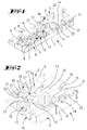
- Fig.1
- eine perspektivische Darstellung des erfindungsgemäß gestalteten Schlosses, und zwar bei weggelassenem Stulp;
- Fig. 2
- eine Herausvergrößerung der Fig. 1 im Bereich der Falle und der Drückernuss;
- Fig. 3
- eine partielle Ausschnittsvergrößerung ähnlich der Fig. 2, jedoch von der anderen Seite gesehen;
- Fig. 4
- eine Draufsicht auf den oberen Bereich des Schlo sses in vergrößerter Darstellung, und zwar bei maximal über den Stulp vorgetretener Falle;
- Fig. 5
- eine der Fig. 4 vergleichbare Darstellung, jedoch bei weniger weiter über den Stulp vorstehender Falle;
- Fig. 6
- eine perspektivische Darstellung der die Fallenvortrittsstellung variierenden Bauteile;
- Fig. 7
- eine perspektivische Darstellung des im Wesentlichen aus zwei Teilen bestehenden Wechselhebels;
- Fig. 8
- eine perspektivische Darstellung des Schiebers mit Blick auf die den Anschlag ausbildende Wandung der Vertiefung;
- Fig. 9
- eine Draufsicht auf das Federelement;
- Fig. 10
- eine Seitenansicht des Federelementes;
- Fig. 11
- den Schnitt nach der Linie XI - XI in Fig. 9 und
- Fig. 12
- eine perspektivische Darstellung des Federelementes.
Claims (14)
- Schlo ss mit einer durch Drehen einer Drückernuss (12) o der durch Betätigen eines Wechselhebels (17) zurückziehbaren Falle (5), wobei der Wechselhebel (17) einen steigenden, vom Schließglied gesteuerten Längsabschnitt (16) und einen daran an einer Anlenkstelle (15) angelenkten, um eine Schwenkachse schwenkbaren Abschnitt (14) aufweist, wobei der schwenkbare Abschnitt (14) am Fallenschwanz (5") angreift, dadurch gekennzeichnet, dass der Anlenkstelle (15) ein von außen verstellbarer Anschlag (26) zugeordnet ist, um die Fallenvortrittsstellung zu variieren.
- Schloss nach Anspruch 1 oder insbesondere danach, dadurch gekennzeichnet, dass der Anschlag (26) von einem quer zum Stulp (2) verlagerbaren Schieber (27) ausgebildet ist.
- Schloss nach einem oder mehreren der vorhergehenden Ansprüche oder insbesondere danach, dadurch gekennzeichnet, dass der Schieber (27) mit einer stulpseitig gelagerten Einstellspindel (31) gewindegekuppelt ist.
- Schloss nach einem oder mehreren der vorhergehenden Ansprüche oder insbesondere danach, dadurch gekennzeichnet, dass der Anschlag (26) von einer Wandung einer Vertiefung (28) des Schiebers (27) ausgebildet ist, welche im Wesentlichen parallel zum Stulp (2) verläuft.
- Schloss nach einem oder mehreren der vorhergehenden Ansprüche oder insbesondere danach, dadurch gekennzeichnet, dass der Schieber (27) zwischen zwei am Schlossboden (3) befestigten Stegen (32, 33) geführt ist.
- Schloss nach einem oder mehreren der vorhergehenden Ansprüche oder insbesondere danach, dadurch gekennzeichnet, dass der schwenkbare Abschnitt (14) des Wechselhebels (17) um die Drückernussnabe (13) drehgelagert ist.
- Schloss nach einem oder mehreren der vorhergehenden Ansprüche oder insbesondere danach, dadurch gekennzeichnet, dass der Anschlag (26) mit einem verlängerten Abschnitt (15') des Gelenkzapfens (15) zusammenwirkt.
- Schloss nach einem oder mehreren der vorhergehenden Ansprüche oder insbesondere danach, dadurch gekennzeichnet, dass die Einstellspindel (31) einen Lagerhals (35) ausbildet, der in einen Einschnitt (36) der stulpseitigen Schlosswandung (37) gelagert ist.
- Schloss nach einem oder mehreren der vorhergehenden Ansprüche oder insbesondere danach, gekennzeichnet durch ein den Lagerhals (35) zumindest teilumfassendes Federelement (38).
- Schloss nach einem oder mehreren der vorhergehenden Ansprüche oder insbesondere danach, dadurch gekennzeichnet, dass das sich parallel zum Stulp (2) erstreckende Federelement (38) eine den Fallenkopf (5') rückwärtig beaufschlagende erste Federzunge (39) ausbildet.
- Schloss nach einem oder mehreren der vorhergehenden Ansprüche oder insbesondere danach, dadurch gekennzeichnet, dass das Federelement (38) eine die Drehbarkeit der Einstellspindel (31) hemmende zweite Federzunge (40) ausbildet, die in eine Umfangsverzahnung (41) der Einstellspindel (31) eingreift.
- Schloss nach einem oder mehreren der vorhergehenden Ansprüche oder insbesondere danach, dadurch gekennzeichnet, dass der den Lagerhals (35) teilumfassende, im Wesentlichen U-förmige Abschnitt (44) des Federelementes (38) freigeschnitten ist und zur Ebene des Federelementes (38) versetzt liegt.
- Schloss nach einem oder mehreren der vorhergehenden Ansprüche oder insbesondere danach, dadurch gekennzeichnet, dass das Federelement (38) eine als Stanzbiegeteil geformte Blattfeder ist.
- Schloss nach einem oder mehreren der vorhergehenden Ansprüche oder insbesondere danach, dadurch gekennzeichnet, dass die Falle (5) eine Keil- oder Pendelfalle und insbesondere austauschbar ist.
Applications Claiming Priority (2)
| Application Number | Priority Date | Filing Date | Title |
|---|---|---|---|
| DE102004003170 | 2004-01-21 | ||
| DE102004003170A DE102004003170A1 (de) | 2004-01-21 | 2004-01-21 | Schloss mit zurückziehbarer Falle |
Publications (2)
| Publication Number | Publication Date |
|---|---|
| EP1557513A1 true EP1557513A1 (de) | 2005-07-27 |
| EP1557513B1 EP1557513B1 (de) | 2006-09-27 |
Family
ID=34625743
Family Applications (1)
| Application Number | Title | Priority Date | Filing Date |
|---|---|---|---|
| EP05100233A Expired - Lifetime EP1557513B1 (de) | 2004-01-21 | 2005-01-17 | Schloss mit zurückziehbarer Falle |
Country Status (3)
| Country | Link |
|---|---|
| EP (1) | EP1557513B1 (de) |
| AT (1) | ATE340911T1 (de) |
| DE (2) | DE102004003170A1 (de) |
Citations (4)
| Publication number | Priority date | Publication date | Assignee | Title |
|---|---|---|---|---|
| FR1543834A (fr) * | 1967-07-06 | 1968-10-25 | Meco Nv | Perfectionnements aux serrures de portes |
| EP0894921A1 (de) * | 1997-08-01 | 1999-02-03 | Vachette | Schliessvorrichtung, insbesondere Einsteckschloss mit einer Falle, für eine Fenstertür oder dergleichen |
| DE29905748U1 (de) * | 1999-03-03 | 2000-08-17 | Karl Fliether Gmbh & Co, 42551 Velbert | Schloß mit umwendbarer Falle |
| DE10133438C1 (de) * | 2001-07-10 | 2003-08-21 | Webasto Kiekert Bustueren Gmbh | Nutzfahrzeug- oder Schienenfahrzeugeinstiegstür |
-
2004
- 2004-01-21 DE DE102004003170A patent/DE102004003170A1/de not_active Withdrawn
-
2005
- 2005-01-17 DE DE502005000112T patent/DE502005000112D1/de not_active Expired - Fee Related
- 2005-01-17 AT AT05100233T patent/ATE340911T1/de not_active IP Right Cessation
- 2005-01-17 EP EP05100233A patent/EP1557513B1/de not_active Expired - Lifetime
Patent Citations (4)
| Publication number | Priority date | Publication date | Assignee | Title |
|---|---|---|---|---|
| FR1543834A (fr) * | 1967-07-06 | 1968-10-25 | Meco Nv | Perfectionnements aux serrures de portes |
| EP0894921A1 (de) * | 1997-08-01 | 1999-02-03 | Vachette | Schliessvorrichtung, insbesondere Einsteckschloss mit einer Falle, für eine Fenstertür oder dergleichen |
| DE29905748U1 (de) * | 1999-03-03 | 2000-08-17 | Karl Fliether Gmbh & Co, 42551 Velbert | Schloß mit umwendbarer Falle |
| DE10133438C1 (de) * | 2001-07-10 | 2003-08-21 | Webasto Kiekert Bustueren Gmbh | Nutzfahrzeug- oder Schienenfahrzeugeinstiegstür |
Also Published As
| Publication number | Publication date |
|---|---|
| ATE340911T1 (de) | 2006-10-15 |
| DE102004003170A1 (de) | 2005-08-11 |
| DE502005000112D1 (de) | 2006-11-09 |
| EP1557513B1 (de) | 2006-09-27 |
Similar Documents
| Publication | Publication Date | Title |
|---|---|---|
| EP2019178B1 (de) | Gelenkstabschloss | |
| EP0634552B1 (de) | Schloss mit Schwenkriegel, insbesondere als Zusatzschloss an Treibstangenschlössern | |
| DE4201069C2 (de) | Getriebe für ein Türschloß, insbesondere ein Rauchschutztürschloß | |
| EP2112304B1 (de) | Schlosseinsatz für ein Glastürschloss | |
| DE102005057926A1 (de) | Schloss mit Schwenkauslöser | |
| WO1996010679A1 (de) | Stangenverschluss | |
| DE4014041A1 (de) | Schliesszylinderbetaetigbares treibstangenschloss | |
| EP1917413B1 (de) | Verschluss zur mehrpunktverriegelung von türen oder wandteilen in gehäusen oder schränken | |
| DE1130325B (de) | Tuerverschluss | |
| DE3148030A1 (de) | Zahnradantrieb in einem schliesszylinderbetaetigbaren treibstangenschloss mit schubriegel | |
| DE3427713C2 (de) | ||
| DE3731879C2 (de) | Schließzylinderbetätigbares Türschloß | |
| DE19815671B4 (de) | Treibstangenverschluß | |
| EP0828048A2 (de) | Schloss, insbesondere Einsteck-schloss | |
| EP0378758A2 (de) | Treibstangenschloss | |
| EP1557513A1 (de) | Schloss mit zurückziehbarer Falle | |
| EP0496076B1 (de) | Treibstangenverschluss | |
| EP0972900B1 (de) | Treibstangenverschluss | |
| DE4405816C2 (de) | Treibstangenschloß | |
| DE4014042A1 (de) | Treibstangenschloss | |
| EP1887151B1 (de) | Gelenkhalterung | |
| DE19756116B4 (de) | Treibstangenverschluß | |
| DE3901957A1 (de) | Treibstangenverschluss, insbesondere fuer balkontueren | |
| DE8532525U1 (de) | Treibstangenschloß mit Schließzylinder | |
| EP0633379B1 (de) | Treibstangenschloss |
Legal Events
| Date | Code | Title | Description |
|---|---|---|---|
| PUAI | Public reference made under article 153(3) epc to a published international application that has entered the european phase |
Free format text: ORIGINAL CODE: 0009012 |
|
| AK | Designated contracting states |
Kind code of ref document: A1 Designated state(s): AT BE BG CH CY CZ DE DK EE ES FI FR GB GR HU IE IS IT LI LT LU MC NL PL PT RO SE SI SK TR |
|
| AX | Request for extension of the european patent |
Extension state: AL BA HR LV MK YU |
|
| 17P | Request for examination filed |
Effective date: 20051207 |
|
| AKX | Designation fees paid |
Designated state(s): AT BE BG CH CY CZ DE DK EE ES FI FR GB GR HU IE IS IT LI LT LU MC NL PL PT RO SE SI SK TR |
|
| GRAP | Despatch of communication of intention to grant a patent |
Free format text: ORIGINAL CODE: EPIDOSNIGR1 |
|
| GRAS | Grant fee paid |
Free format text: ORIGINAL CODE: EPIDOSNIGR3 |
|
| RAP1 | Party data changed (applicant data changed or rights of an application transferred) |
Owner name: KFV KARL FLIETHER GMBH & CO. KG |
|
| GRAA | (expected) grant |
Free format text: ORIGINAL CODE: 0009210 |
|
| AK | Designated contracting states |
Kind code of ref document: B1 Designated state(s): AT BE BG CH CY CZ DE DK EE ES FI FR GB GR HU IE IS IT LI LT LU MC NL PL PT RO SE SI SK TR |
|
| PG25 | Lapsed in a contracting state [announced via postgrant information from national office to epo] |
Ref country code: RO Free format text: LAPSE BECAUSE OF FAILURE TO SUBMIT A TRANSLATION OF THE DESCRIPTION OR TO PAY THE FEE WITHIN THE PRESCRIBED TIME-LIMIT Effective date: 20060927 Ref country code: IT Free format text: LAPSE BECAUSE OF FAILURE TO SUBMIT A TRANSLATION OF THE DESCRIPTION OR TO PAY THE FEE WITHIN THE PRESCRIBED TIME-LIMIT;WARNING: LAPSES OF ITALIAN PATENTS WITH EFFECTIVE DATE BEFORE 2007 MAY HAVE OCCURRED AT ANY TIME BEFORE 2007. THE CORRECT EFFECTIVE DATE MAY BE DIFFERENT FROM THE ONE RECORDED. Effective date: 20060927 Ref country code: FI Free format text: LAPSE BECAUSE OF FAILURE TO SUBMIT A TRANSLATION OF THE DESCRIPTION OR TO PAY THE FEE WITHIN THE PRESCRIBED TIME-LIMIT Effective date: 20060927 Ref country code: PL Free format text: LAPSE BECAUSE OF FAILURE TO SUBMIT A TRANSLATION OF THE DESCRIPTION OR TO PAY THE FEE WITHIN THE PRESCRIBED TIME-LIMIT Effective date: 20060927 Ref country code: CZ Free format text: LAPSE BECAUSE OF FAILURE TO SUBMIT A TRANSLATION OF THE DESCRIPTION OR TO PAY THE FEE WITHIN THE PRESCRIBED TIME-LIMIT Effective date: 20060927 Ref country code: SI Free format text: LAPSE BECAUSE OF FAILURE TO SUBMIT A TRANSLATION OF THE DESCRIPTION OR TO PAY THE FEE WITHIN THE PRESCRIBED TIME-LIMIT Effective date: 20060927 Ref country code: IE Free format text: LAPSE BECAUSE OF FAILURE TO SUBMIT A TRANSLATION OF THE DESCRIPTION OR TO PAY THE FEE WITHIN THE PRESCRIBED TIME-LIMIT Effective date: 20060927 Ref country code: SK Free format text: LAPSE BECAUSE OF FAILURE TO SUBMIT A TRANSLATION OF THE DESCRIPTION OR TO PAY THE FEE WITHIN THE PRESCRIBED TIME-LIMIT Effective date: 20060927 Ref country code: LT Free format text: LAPSE BECAUSE OF FAILURE TO SUBMIT A TRANSLATION OF THE DESCRIPTION OR TO PAY THE FEE WITHIN THE PRESCRIBED TIME-LIMIT Effective date: 20060927 |
|
| REG | Reference to a national code |
Ref country code: GB Ref legal event code: FG4D Free format text: NOT ENGLISH |
|
| REG | Reference to a national code |
Ref country code: CH Ref legal event code: EP Ref country code: CH Ref legal event code: NV Representative=s name: R. A. EGLI & CO. PATENTANWAELTE |
|
| REG | Reference to a national code |
Ref country code: IE Ref legal event code: FG4D Free format text: LANGUAGE OF EP DOCUMENT: GERMAN |
|
| REF | Corresponds to: |
Ref document number: 502005000112 Country of ref document: DE Date of ref document: 20061109 Kind code of ref document: P |
|
| GBT | Gb: translation of ep patent filed (gb section 77(6)(a)/1977) |
Effective date: 20061128 |
|
| PG25 | Lapsed in a contracting state [announced via postgrant information from national office to epo] |
Ref country code: SE Free format text: LAPSE BECAUSE OF FAILURE TO SUBMIT A TRANSLATION OF THE DESCRIPTION OR TO PAY THE FEE WITHIN THE PRESCRIBED TIME-LIMIT Effective date: 20061227 Ref country code: BG Free format text: LAPSE BECAUSE OF FAILURE TO SUBMIT A TRANSLATION OF THE DESCRIPTION OR TO PAY THE FEE WITHIN THE PRESCRIBED TIME-LIMIT Effective date: 20061227 Ref country code: DK Free format text: LAPSE BECAUSE OF FAILURE TO SUBMIT A TRANSLATION OF THE DESCRIPTION OR TO PAY THE FEE WITHIN THE PRESCRIBED TIME-LIMIT Effective date: 20061227 |
|
| PG25 | Lapsed in a contracting state [announced via postgrant information from national office to epo] |
Ref country code: ES Free format text: LAPSE BECAUSE OF FAILURE TO SUBMIT A TRANSLATION OF THE DESCRIPTION OR TO PAY THE FEE WITHIN THE PRESCRIBED TIME-LIMIT Effective date: 20070107 |
|
| PG25 | Lapsed in a contracting state [announced via postgrant information from national office to epo] |
Ref country code: IS Free format text: LAPSE BECAUSE OF FAILURE TO SUBMIT A TRANSLATION OF THE DESCRIPTION OR TO PAY THE FEE WITHIN THE PRESCRIBED TIME-LIMIT Effective date: 20070127 |
|
| PG25 | Lapsed in a contracting state [announced via postgrant information from national office to epo] |
Ref country code: MC Free format text: LAPSE BECAUSE OF NON-PAYMENT OF DUE FEES Effective date: 20070131 |
|
| ET | Fr: translation filed | ||
| PG25 | Lapsed in a contracting state [announced via postgrant information from national office to epo] |
Ref country code: PT Free format text: LAPSE BECAUSE OF FAILURE TO SUBMIT A TRANSLATION OF THE DESCRIPTION OR TO PAY THE FEE WITHIN THE PRESCRIBED TIME-LIMIT Effective date: 20070313 |
|
| REG | Reference to a national code |
Ref country code: IE Ref legal event code: FD4D |
|
| PLBE | No opposition filed within time limit |
Free format text: ORIGINAL CODE: 0009261 |
|
| STAA | Information on the status of an ep patent application or granted ep patent |
Free format text: STATUS: NO OPPOSITION FILED WITHIN TIME LIMIT |
|
| 26N | No opposition filed |
Effective date: 20070628 |
|
| PG25 | Lapsed in a contracting state [announced via postgrant information from national office to epo] |
Ref country code: GR Free format text: LAPSE BECAUSE OF FAILURE TO SUBMIT A TRANSLATION OF THE DESCRIPTION OR TO PAY THE FEE WITHIN THE PRESCRIBED TIME-LIMIT Effective date: 20061228 |
|
| PG25 | Lapsed in a contracting state [announced via postgrant information from national office to epo] |
Ref country code: EE Free format text: LAPSE BECAUSE OF FAILURE TO SUBMIT A TRANSLATION OF THE DESCRIPTION OR TO PAY THE FEE WITHIN THE PRESCRIBED TIME-LIMIT Effective date: 20060927 |
|
| PGFP | Annual fee paid to national office [announced via postgrant information from national office to epo] |
Ref country code: AT Payment date: 20090122 Year of fee payment: 5 |
|
| PGFP | Annual fee paid to national office [announced via postgrant information from national office to epo] |
Ref country code: DE Payment date: 20090211 Year of fee payment: 5 Ref country code: NL Payment date: 20090127 Year of fee payment: 5 |
|
| PGFP | Annual fee paid to national office [announced via postgrant information from national office to epo] |
Ref country code: CH Payment date: 20090130 Year of fee payment: 5 Ref country code: GB Payment date: 20090122 Year of fee payment: 5 |
|
| PGRI | Patent reinstated in contracting state [announced from national office to epo] |
Ref country code: IT Effective date: 20090301 |
|
| PGFP | Annual fee paid to national office [announced via postgrant information from national office to epo] |
Ref country code: BE Payment date: 20090129 Year of fee payment: 5 |
|
| PG25 | Lapsed in a contracting state [announced via postgrant information from national office to epo] |
Ref country code: LU Free format text: LAPSE BECAUSE OF NON-PAYMENT OF DUE FEES Effective date: 20070117 Ref country code: CY Free format text: LAPSE BECAUSE OF FAILURE TO SUBMIT A TRANSLATION OF THE DESCRIPTION OR TO PAY THE FEE WITHIN THE PRESCRIBED TIME-LIMIT Effective date: 20060927 |
|
| PGFP | Annual fee paid to national office [announced via postgrant information from national office to epo] |
Ref country code: IT Payment date: 20090126 Year of fee payment: 5 |
|
| PG25 | Lapsed in a contracting state [announced via postgrant information from national office to epo] |
Ref country code: HU Free format text: LAPSE BECAUSE OF FAILURE TO SUBMIT A TRANSLATION OF THE DESCRIPTION OR TO PAY THE FEE WITHIN THE PRESCRIBED TIME-LIMIT Effective date: 20070328 Ref country code: TR Free format text: LAPSE BECAUSE OF FAILURE TO SUBMIT A TRANSLATION OF THE DESCRIPTION OR TO PAY THE FEE WITHIN THE PRESCRIBED TIME-LIMIT Effective date: 20060927 |
|
| PGFP | Annual fee paid to national office [announced via postgrant information from national office to epo] |
Ref country code: FR Payment date: 20090119 Year of fee payment: 5 |
|
| BERE | Be: lapsed |
Owner name: KFV KARL FLIETHER G.M.B.H. & CO. KG Effective date: 20100131 |
|
| REG | Reference to a national code |
Ref country code: NL Ref legal event code: V1 Effective date: 20100801 |
|
| REG | Reference to a national code |
Ref country code: CH Ref legal event code: PL |
|
| GBPC | Gb: european patent ceased through non-payment of renewal fee |
Effective date: 20100117 |
|
| REG | Reference to a national code |
Ref country code: FR Ref legal event code: ST Effective date: 20100930 |
|
| PG25 | Lapsed in a contracting state [announced via postgrant information from national office to epo] |
Ref country code: LI Free format text: LAPSE BECAUSE OF NON-PAYMENT OF DUE FEES Effective date: 20100131 Ref country code: NL Free format text: LAPSE BECAUSE OF NON-PAYMENT OF DUE FEES Effective date: 20100801 Ref country code: FR Free format text: LAPSE BECAUSE OF NON-PAYMENT OF DUE FEES Effective date: 20100201 Ref country code: CH Free format text: LAPSE BECAUSE OF NON-PAYMENT OF DUE FEES Effective date: 20100131 |
|
| PG25 | Lapsed in a contracting state [announced via postgrant information from national office to epo] |
Ref country code: AT Free format text: LAPSE BECAUSE OF NON-PAYMENT OF DUE FEES Effective date: 20100117 Ref country code: DE Free format text: LAPSE BECAUSE OF NON-PAYMENT OF DUE FEES Effective date: 20100803 |
|
| PG25 | Lapsed in a contracting state [announced via postgrant information from national office to epo] |
Ref country code: GB Free format text: LAPSE BECAUSE OF NON-PAYMENT OF DUE FEES Effective date: 20100117 |
|
| PG25 | Lapsed in a contracting state [announced via postgrant information from national office to epo] |
Ref country code: BE Free format text: LAPSE BECAUSE OF NON-PAYMENT OF DUE FEES Effective date: 20100131 |
|
| PG25 | Lapsed in a contracting state [announced via postgrant information from national office to epo] |
Ref country code: IT Free format text: LAPSE BECAUSE OF NON-PAYMENT OF DUE FEES Effective date: 20100117 |