EP1557514B1 - Crémone-serrure pour porte à double battants avec fonction anti-panique - Google Patents
Crémone-serrure pour porte à double battants avec fonction anti-panique Download PDFInfo
- Publication number
- EP1557514B1 EP1557514B1 EP05100225A EP05100225A EP1557514B1 EP 1557514 B1 EP1557514 B1 EP 1557514B1 EP 05100225 A EP05100225 A EP 05100225A EP 05100225 A EP05100225 A EP 05100225A EP 1557514 B1 EP1557514 B1 EP 1557514B1
- Authority
- EP
- European Patent Office
- Prior art keywords
- control
- catch
- driving
- roller
- leaf
- Prior art date
- Legal status (The legal status is an assumption and is not a legal conclusion. Google has not performed a legal analysis and makes no representation as to the accuracy of the status listed.)
- Expired - Lifetime
Links
- 238000006073 displacement reaction Methods 0.000 claims description 12
- 230000005540 biological transmission Effects 0.000 claims description 3
- 230000008878 coupling Effects 0.000 description 2
- 238000010168 coupling process Methods 0.000 description 2
- 238000005859 coupling reaction Methods 0.000 description 2
- 238000005516 engineering process Methods 0.000 description 2
- 230000002349 favourable effect Effects 0.000 description 2
- 239000000446 fuel Substances 0.000 description 2
- 239000003380 propellant Substances 0.000 description 2
- 241000288673 Chiroptera Species 0.000 description 1
- 241001295925 Gegenes Species 0.000 description 1
- 230000015572 biosynthetic process Effects 0.000 description 1
- 230000000994 depressogenic effect Effects 0.000 description 1
- 210000004417 patella Anatomy 0.000 description 1
- 238000005096 rolling process Methods 0.000 description 1
- 230000006641 stabilisation Effects 0.000 description 1
- 238000011105 stabilization Methods 0.000 description 1
Images


Classifications
-
- E—FIXED CONSTRUCTIONS
- E05—LOCKS; KEYS; WINDOW OR DOOR FITTINGS; SAFES
- E05C—BOLTS OR FASTENING DEVICES FOR WINGS, SPECIALLY FOR DOORS OR WINDOWS
- E05C7/00—Fastening devices specially adapted for two wings
- E05C7/04—Fastening devices specially adapted for two wings for wings which abut when closed
-
- E—FIXED CONSTRUCTIONS
- E05—LOCKS; KEYS; WINDOW OR DOOR FITTINGS; SAFES
- E05B—LOCKS; ACCESSORIES THEREFOR; HANDCUFFS
- E05B65/00—Locks or fastenings for special use
- E05B65/10—Locks or fastenings for special use for panic or emergency doors
- E05B65/1086—Locks with panic function, e.g. allowing opening from the inside without a ley even when locked from the outside
-
- E—FIXED CONSTRUCTIONS
- E05—LOCKS; KEYS; WINDOW OR DOOR FITTINGS; SAFES
- E05C—BOLTS OR FASTENING DEVICES FOR WINGS, SPECIALLY FOR DOORS OR WINDOWS
- E05C9/00—Arrangements of simultaneously actuated bolts or other securing devices at well-separated positions on the same wing
- E05C9/04—Arrangements of simultaneously actuated bolts or other securing devices at well-separated positions on the same wing with two sliding bars moved in opposite directions when fastening or unfastening
- E05C9/047—Arrangements of simultaneously actuated bolts or other securing devices at well-separated positions on the same wing with two sliding bars moved in opposite directions when fastening or unfastening comprising key-operated locks, e.g. a lock cylinder to drive auxiliary deadbolts or latch bolts
-
- E—FIXED CONSTRUCTIONS
- E05—LOCKS; KEYS; WINDOW OR DOOR FITTINGS; SAFES
- E05C—BOLTS OR FASTENING DEVICES FOR WINGS, SPECIALLY FOR DOORS OR WINDOWS
- E05C9/00—Arrangements of simultaneously actuated bolts or other securing devices at well-separated positions on the same wing
- E05C9/04—Arrangements of simultaneously actuated bolts or other securing devices at well-separated positions on the same wing with two sliding bars moved in opposite directions when fastening or unfastening
- E05C9/042—Arrangements of simultaneously actuated bolts or other securing devices at well-separated positions on the same wing with two sliding bars moved in opposite directions when fastening or unfastening with pins engaging slots
Definitions
- the invention relates to amaschineriegelver gleich for two-leaf doors with panic function, with a fixed wing lock, which by moving a pusher nut displaceable espagnolette slide for retractingkulturriegeln, being displaced during actuation of the follower control members to the case and the latch of a moving wing lock to control from the trap and latch inlet openings of the inactive leaf, wherein at least one of the control members, in particular the one associated with the case, has a pivotable about a housing-fixed axis control lever which can act on a Fallenstin control section.
- Such a bolt lock is known from German Offenlegungsschrift 2611359, wherein the latch associated with the control lever is formed on one arm and above the upper edge of the trap on the poppet castle stores.
- the upper drive rod connecting slide acts on a sloping flank of the control lever and pivots it so that its free end abuts against the trap front and pushes back the trap.
- the bolt is also relocated via control members. This design requires an absolute freedom of play.
- the one-armed control lever associated with the trap must not make any lateral evasive movement, as it can no longer act on the bats.
- a similar espagnolette describes the FR 23 44 695 ,
- the pusher has a sprocket. This attacks in racks of downwardly and upwardly displaceable drive rods.
- the drive rods control the control elements, which in the course of a drive rod displacement, the latch and the bolt of a moving wing lock out of the bolt entry openings of the inactive gate lock.
- the invention has for its object to design amaschineriegelver gleich of the type in question so that in particular in case of panic a reliable unlocking function is ensured.
- control lever forms a toggle mechanism together with a hinged to an arm of the follower and the control section handlebar.
- the control roller is a single roller of a twin roller, in which a single roller is in each case located on one broad side of the control section. It does not therefore have to be two differently designed Padlocks are manufactured and stored.
- Another advantageous feature is the fact that the handlebar, forming an arcuate form, the nut hub of the pusher nut partially includes.
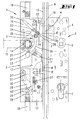
- the bolt-on bolt closure designated as a whole by the number 1, is used on double-leaf doors with a panic function.
- the propellant bolt closure 1 has a lock 2 to be assigned to the inactive leaf, which cooperates with a moving leaf lock 3.
- the active leaf lock 3 has a lock ssgephaseuse 4 with this stored, split nut 5.
- a door handle provided inside the door nut 5 is displaced to withdraw a case 6 of the active leaf lock 3.
- the lock housing 4 receives a lock cylinder 7.
- a guided below the case 6 bolt 8 of the moving leaf lock 3 is displaced.
- a face plate 9 of the active leaf lock 3 is connected with the lock housing 4, a face plate 9 of the active leaf lock 3 is connected.
- the forend 9 is penetrated by the case 6 and the bolt 8.
- the case 6 and the bolt 8 pass through in the pre-set position and latch and bolt entry openings 10 and 11 of a faceplate 12 of the poppet lock 2.
- these In the installed state of the poppet lock 2 and moving leaf lock 3, these have a small distance to each other, which in the embodiment is about 4 - 5 mm.
- the lock housing 13 of the passive leaf lock 2 is attached to the faceplate 12, the lock housing 13 of the passive leaf lock 2 is attached.
- the latter can be rotatably mounted in the upper area a pusher 14.
- the same can be depressed by means of a door inside, dash-dotted illustrated door handle 15 in the normal pusher actuation direction.
- the follower shift is transferred to two in the closure housing 13 guided in the vertical direction of the drive rod connecting slide 16, 17.
- the same are provided with coupling projections 18 and 19 for attaching, not shown drive rods. These occur in the Fig. 1 illustrated closure position in engagement with unillustrated engagement openings and give the passive leaf its closed position.
- the drive rod connection slide 16, 17 have obliquely to their direction of displacement extending longitudinal slots 20 and 21, respectively. In this engage coupling pins 22 and 23, which in turn sit on arms 24 and 25 of the Drükkernuss 14. This means that the drive rod connection slide 16, 17 are displaced in opposite directions by pusher displacement.
- a pivot lever 26 is mounted about a lock housing side standing pin 27.
- a pin-like carrier 28 of the pivot lever 26 engages in a transverse slot 29 of the drive rod connection slide 17, whereby upon its displacement of the pivot lever 26 undergoes a swing.
- the curved slot 30 is laid so that it extends eccentrically to the upright pin 27. Due to this orientation, a forward displacement of the spool 31 upon displacement of the drive rod connecting slide 17th
- the case 6 is associated with a control lever 32.
- Whose housing-fixed axis 33 extends near the faceplate 12 above the trap inlet opening 10.
- the control lever 32 is rectilinear. This rectilinear portion is adjoined by a control section 34 which extends at an obtuse angle to the rectilinear section. At the same end it carries a pivot pin 35 on which a handlebar 36 engages with its one end. The other end of the handlebar 36 is pivotally connected via a pin 37 to the arm 25 of the follower 14. In this way, the control lever 32 forms together with the handlebar 36, a toggle G.
- control roller 38 In the area of the control lever 32 connected to the handlebar 36 joint, so the pivot pin 35, sits a the end edge 6 'of the case 6 acting on the control roller 38. The latter sits on Accordingly, the control roller 38 is also in the region of an angling of the control section 34.
- the journal 39 is located at the level of the kink of the control lever 32, at which kink, the control section 34 connects in obtuse angled orientation.
- the diameter of the control roller 38 is chosen so large that the outer periphery of the control roller 38, the control lever 32 and control section 34 on the case 6 facing side surmounted.
- the control roller 38 extends in the plane of the end edge 6 'of the case 6.
- control roller 38 is a single role of a twin role, in each of which a single roll 38, 38' each lie on a broad side of the control section 34.
- the control roller 38 or 38 ' in some respects a patella of the toggle G. Due to the formation of the two individual rollers 38, 38' to a twin role turning the case 6 by 180 ° about the longitudinal axis of the trap is possible, so that the passive Lock 2 can be used for both right and left locks of the active leaf.
- the control roller 38 of the toggle gear G is spaced in the case trailing position of the end 6 'of the case 6. In the present case, it is about 3 mm. This means that, before the control roller 38 reaches the trap end 6 ', a corresponding idle stroke takes place.
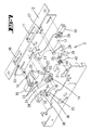
- Fig. 7 From the exploded view according to Fig. 7 shows that the lock contains a torsion spring 40. The same is attached to the uprights 27. The longer spring arm 40 'acts on the driver 28 such that the pivot lever 26 is charged in the counterclockwise direction, whereby the position according to Fig. 1 is held by spring force.
- the nut 5 can be operated by means of the nut 5 associated with the inner handle, wherein both the case 6 and the latch 8 are withdrawn and accordingly leave the inlet openings 10 and 11.
- the active leaf is thus convertible into the open position.
- the latter has a shared design nut 5, so that in the respective operation of the nut from the inside of the door only the inner half of the nut is taken. In such a case, only the active leaf is opened in a panic function.
- the two-leaf door can be opened in a panic case.
- the displacement of the door handle 15 in such a situation initially leads to the intermediate position according to Fig. 2 and 3 entry.
- the door handle 15 is displaced by a few degrees, while the arcuately guided around the Nussnabe handlebar 36 performs an upward movement and thereby causes buckling of the toggle G, wherein the control roller 38 after passing through a free travel in investment position to the bale 6 'occurs.
- the control slide 31 is advanced over the pivot lever 26 to the tactile projection 8 'of the bolt 8. If the door handle 15 is further displaced in the downward direction to the position according to Fig.
- the pivoting of the door handle 15 may be up to 45 °, so that on a long way, the control of the case 6 and the bolt 8 takes place.
- the forces acting on the latch 6 lever transfer forces increase with increasing rotation of the follower 14.
- the toggle gear G leads to a stabilization of the control lever 32, so that always a reliable control of the case 6 is ensured in case of panic.
Landscapes
- Engineering & Computer Science (AREA)
- Mechanical Engineering (AREA)
- Business, Economics & Management (AREA)
- Emergency Management (AREA)
- Lock And Its Accessories (AREA)
- Securing Of Glass Panes Or The Like (AREA)
- Special Wing (AREA)
- Adornments (AREA)
Claims (8)
- Serrure à crémone pour porte à double vantour avec fonction anti-panique, avec une serrure (2), associée au vantail semi-fixe, qui présente des coulisseaux de raccordement de tringles de crémone (16, 17), déplaçables par actionnement d'un fouillot de poignée (14), pour la rétraction de tringles de crémone, des organes de commande étant déplacés, lors de l'actionnement du fouillot de poignée, pour commander le pêne demi-tour (6) et le verrou (8) d'une serrure à vantail mobile, hors des ouvertures d'entrée de pêne demi-tour et de verrou de la serrure à vantaux fixes (3), au moins l'un des organes de commande, en particulier celui associé au pêne demi-tour (6), présentant un levier de commande (32) susceptible de pivoter autour d'un axe (33) fixe par rapport au boîtier, pouvant solliciter le front de pêne demi-tour (6') avec un tronçon de commande (34), caractérisée en ce que le levier de commande (32), conjointement avec une bielle (36), articulée à un bras (25) du fouillot de poignée (14) et sur le tronçon de commande (34), constitue une transmission à levier à genouillère (G).
- Serrure à crémone selon la revendication 1, caractérisée en ce qu'un galet de commande (38, 38'), sollicitant l'arête frontale (6') du pêne demi-tour (6), est placé dans la zone de l'articulation (39) reliant le levier de commande (32) à la bielle (36).
- Serrure à crémone selon la revendication 2, caractérisée en ce que le galet de commande (38, 38') est placé dans la zone d'un coudage du tronçon de commande (34).
- Serrure à crémone selon la revendication 2 ou 3, caractérisée en ce que le galet de commande (38, 38') est un galet de commande individuel d'un galet jumeau, pour lequel chaque fois un galet individuel (38, 38') est situé sur une face large du tronçon de commande (34).
- Serrure à crémone selon l'une des revendications précédentes, caractérisée en ce que la bielle (36) forme un arc et entoure partiellement le moyeu de fouillot du fouillot de poignée (14).
- Serrure à crémone selon l'une des revendications précédentes, caractérisée en ce que l'autre organe de commande est un coulisseau de commande (31), en particulier associé au verrou (8), manoeuvré par un levier pivotant (26), manoeuvré de son côté par le coulisseau de raccordement de tringles de crémone (17).
- Serrure à crémone selon l'une des revendications 2 à 6, caractérisée en ce que le galet de commande (38, ou 38') de la transmission à levier à genouillère (G), à la position de sortie de pêne demi-tour, est espacé du front (6') du pêne demi-tour (6).
- Serrure à crémone selon l'une des revendications précédentes, caractérisée en ce que, lors de la rotation du fouillot de poignée (14), les efforts de transmission par levier, agissant sur le pêne demi-tour (6), avec le déplacement croissant rotation du fouillot.
Applications Claiming Priority (2)
| Application Number | Priority Date | Filing Date | Title |
|---|---|---|---|
| DE102004003168 | 2004-01-21 | ||
| DE102004003168A DE102004003168B4 (de) | 2004-01-21 | 2004-01-21 | Treibriegelverschluss für zweiflügelige Türen mit Panikfunktion |
Publications (2)
| Publication Number | Publication Date |
|---|---|
| EP1557514A1 EP1557514A1 (fr) | 2005-07-27 |
| EP1557514B1 true EP1557514B1 (fr) | 2008-04-23 |
Family
ID=34625742
Family Applications (1)
| Application Number | Title | Priority Date | Filing Date |
|---|---|---|---|
| EP05100225A Expired - Lifetime EP1557514B1 (fr) | 2004-01-21 | 2005-01-17 | Crémone-serrure pour porte à double battants avec fonction anti-panique |
Country Status (3)
| Country | Link |
|---|---|
| EP (1) | EP1557514B1 (fr) |
| AT (1) | ATE393280T1 (fr) |
| DE (2) | DE102004003168B4 (fr) |
Cited By (1)
| Publication number | Priority date | Publication date | Assignee | Title |
|---|---|---|---|---|
| US7526933B2 (en) | 2006-10-18 | 2009-05-05 | Master Lock Company Llc | Multipoint door lock |
Families Citing this family (15)
| Publication number | Priority date | Publication date | Assignee | Title |
|---|---|---|---|---|
| DE102004009973B4 (de) * | 2004-03-01 | 2007-03-22 | Wilh. Schlechtendahl & Söhne GmbH & Co KG | Gegenkasten für ein Paniktürschloß |
| DE202005002908U1 (de) * | 2005-02-22 | 2005-06-16 | Bks Gmbh | Einsteckschloß |
| DE102005015248B4 (de) * | 2005-04-02 | 2010-01-21 | Wilka Schließtechnik GmbH | Standflügelschloss mit einem elektrischen Türöffner |
| DE202007000599U1 (de) * | 2007-01-10 | 2007-03-15 | Kfv Karl Fliether Gmbh & Co. Kg | Verriegelungsbeschlag |
| IT1392634B1 (it) * | 2009-02-03 | 2012-03-16 | Antipanic S R L | Porta di sicurezza |
| DE102009003860B4 (de) | 2009-04-30 | 2015-10-22 | Wilka Schließtechnik GmbH | Panikschloss mit durch Betätigung eines der Riegelstirn zugeordneten Auslösers aushebbarer Zuhaltung |
| DE102009025469B3 (de) † | 2009-06-15 | 2011-04-14 | Bks Gmbh | Treibriegelschloss |
| EP2362042B1 (fr) * | 2010-02-19 | 2012-08-22 | BKS GmbH | Crémone espagnolette anti-panique |
| AT509464B1 (de) * | 2010-03-03 | 2011-09-15 | Roto Frank Ag | Schloss |
| DE102012111881B4 (de) | 2012-12-06 | 2021-12-30 | WILKA Schließtechnik GmbH | Motorisch betreibbares Standflügelschloss mit Riegel- und Fallenauswerfer |
| DE102014222894A1 (de) | 2014-11-10 | 2016-05-12 | Aug. Winkhaus Gmbh & Co. Kg | Gegenschloss eines Treibstangenschlosses einer zweiflügeligen Tür |
| DE102016225005A1 (de) * | 2016-12-14 | 2018-06-14 | Geze Gmbh | Verriegelungsanordnung für eine zweiflügelige Tür |
| DE102016225000B4 (de) * | 2016-12-14 | 2021-08-19 | Geze Gmbh | Verriegelungsanordnung für eine zweiflügelige tür |
| DE102016225010A1 (de) * | 2016-12-14 | 2018-06-14 | Geze Gmbh | Verriegelungsanordnung für eine zweiflügelige Tür |
| EP3543437B1 (fr) * | 2018-03-22 | 2020-10-07 | dormakaba Deutschland GmbH | Dispositif formant serrure pourvu d'une serrure pour une porte à battants mobiles |
Family Cites Families (8)
| Publication number | Priority date | Publication date | Assignee | Title |
|---|---|---|---|---|
| US2029901A (en) * | 1934-12-12 | 1936-02-04 | Sargent & Co | Exit doorlock |
| DE2611359C2 (de) * | 1976-03-18 | 1983-08-04 | Scovill Sicherheitseinrichtungen Gmbh, 5620 Velbert | Treibstangenverschluß für Türflügel |
| DE2738746C3 (de) * | 1977-08-27 | 1981-10-08 | Fa. Karl Fliether, 5620 Velbert | Auslösevorrichtung für ein Paniktürschloß mit Falle und Riegel |
| DE2914372C2 (de) * | 1979-04-10 | 1984-04-05 | Scovill Sicherheitseinrichtungen Gmbh, 5620 Velbert | Von außen aufschließbares Fallen-Schubriegel-Panikschloß |
| DE9011099U1 (de) * | 1990-07-27 | 1990-10-04 | Wilh. Schlechtendahl & Söhne GmbH & Co KG, 5628 Heiligenhaus | Paniktürverschluß |
| DE4033840C2 (de) * | 1990-10-24 | 1994-12-01 | W Dipl Ing Knicker | Elektromagnetisch betätigbarer Türöffner mit Panikfunktion |
| DE9409846U1 (de) * | 1994-06-21 | 1994-09-15 | Bks Gmbh, 42549 Velbert | Panik-Treibstangenschloß |
| DE19652601C1 (de) * | 1996-12-18 | 1998-06-25 | Dorma Gmbh & Co Kg | Ent- und Verriegelung für eine einen Standflügel und einen Gangflügel aufweisende Tür |
-
2004
- 2004-01-21 DE DE102004003168A patent/DE102004003168B4/de not_active Expired - Fee Related
-
2005
- 2005-01-17 EP EP05100225A patent/EP1557514B1/fr not_active Expired - Lifetime
- 2005-01-17 AT AT05100225T patent/ATE393280T1/de active
- 2005-01-17 DE DE502005003792T patent/DE502005003792D1/de not_active Expired - Lifetime
Cited By (1)
| Publication number | Priority date | Publication date | Assignee | Title |
|---|---|---|---|---|
| US7526933B2 (en) | 2006-10-18 | 2009-05-05 | Master Lock Company Llc | Multipoint door lock |
Also Published As
| Publication number | Publication date |
|---|---|
| DE502005003792D1 (de) | 2008-06-05 |
| DE102004003168B4 (de) | 2008-10-23 |
| DE102004003168A1 (de) | 2005-08-18 |
| ATE393280T1 (de) | 2008-05-15 |
| EP1557514A1 (fr) | 2005-07-27 |
Similar Documents
| Publication | Publication Date | Title |
|---|---|---|
| EP1932989B1 (fr) | Système de fermeture pour portes, fenêtres ou analogues, en particulier crémone-serrure à fonction d'urgence et de verrouillage à plusieurs points | |
| EP0854261B1 (fr) | Serrure autobloquante | |
| EP0413177B1 (fr) | Serrure pour bielle motrice | |
| DE102004003168B4 (de) | Treibriegelverschluss für zweiflügelige Türen mit Panikfunktion | |
| EP2264268B1 (fr) | Crémone serrure | |
| DE102006059568A1 (de) | Schließanlage für Türen, Fenster oder dergleichen, insbesondere Treibstangenschloss mit Panikfunktion und Mehrpunktverriegelung | |
| EP0945572B1 (fr) | Ensemble de serrure de porte, de préférence crémone-serrure | |
| EP2460957A1 (fr) | Serrure dotée d'une fonction d'urgence | |
| EP1574644A2 (fr) | Système de verrouillage pour portes, fenêtres ou similaires, notamment crémone-serrure avec fonction anti-panique et avec plusieurs points de condamnation | |
| DE4303400C2 (de) | Treibstangenschloss mit Abdicht- und Sicherheitsfunktion ß | |
| EP2072723A2 (fr) | Crémone-serrure | |
| EP1020597A1 (fr) | Serrure à crémone avec une serrure principal et une serrure complémentaire | |
| EP2339096B1 (fr) | Serrure à crémone dotée d'une fonction anti-panique et d'un verrouillage multiple | |
| DE10107744B4 (de) | Treibstangenverschluss | |
| DE2738746B2 (de) | Auslösevorrichtung für ein Paniktürschloß mit Falle und Riegel | |
| DE102005039287A1 (de) | Antipanikschloss | |
| DE4006687A1 (de) | Treibstangenschloss mit von einem zentralschloss gesteuertem zusatzschloss | |
| EP3122970B1 (fr) | Serrure à loqueteau pour barre de verrouillage avec ressort | |
| EP0974721B1 (fr) | Serrure à plusieurs pênes | |
| EP3216952B1 (fr) | Dispositif de verrouillage | |
| EP0990758A2 (fr) | Serrure additionelle pour crémone | |
| EP0972900A2 (fr) | Crémone-serrure | |
| EP1057956A1 (fr) | Crémone-serrure avec une serrure principale et une serrure auxiliaire | |
| EP2072724A2 (fr) | Crémone-serrure | |
| EP0790376B1 (fr) | Serrure à Crémone |
Legal Events
| Date | Code | Title | Description |
|---|---|---|---|
| PUAI | Public reference made under article 153(3) epc to a published international application that has entered the european phase |
Free format text: ORIGINAL CODE: 0009012 |
|
| AK | Designated contracting states |
Kind code of ref document: A1 Designated state(s): AT BE BG CH CY CZ DE DK EE ES FI FR GB GR HU IE IS IT LI LT LU MC NL PL PT RO SE SI SK TR |
|
| AX | Request for extension of the european patent |
Extension state: AL BA HR LV MK YU |
|
| 17P | Request for examination filed |
Effective date: 20060120 |
|
| AKX | Designation fees paid |
Designated state(s): AT BE BG CH CY CZ DE DK EE ES FI FR GB GR HU IE IS IT LI LT LU MC NL PL PT RO SE SI SK TR |
|
| 17Q | First examination report despatched |
Effective date: 20061114 |
|
| GRAP | Despatch of communication of intention to grant a patent |
Free format text: ORIGINAL CODE: EPIDOSNIGR1 |
|
| GRAS | Grant fee paid |
Free format text: ORIGINAL CODE: EPIDOSNIGR3 |
|
| GRAA | (expected) grant |
Free format text: ORIGINAL CODE: 0009210 |
|
| AK | Designated contracting states |
Kind code of ref document: B1 Designated state(s): AT BE BG CH CY CZ DE DK EE ES FI FR GB GR HU IE IS IT LI LT LU MC NL PL PT RO SE SI SK TR |
|
| REG | Reference to a national code |
Ref country code: GB Ref legal event code: FG4D Free format text: NOT ENGLISH |
|
| REG | Reference to a national code |
Ref country code: CH Ref legal event code: EP |
|
| REF | Corresponds to: |
Ref document number: 502005003792 Country of ref document: DE Date of ref document: 20080605 Kind code of ref document: P |
|
| REG | Reference to a national code |
Ref country code: IE Ref legal event code: FG4D Free format text: LANGUAGE OF EP DOCUMENT: GERMAN |
|
| REG | Reference to a national code |
Ref country code: CH Ref legal event code: NV Representative=s name: R. A. EGLI & CO. PATENTANWAELTE |
|
| PG25 | Lapsed in a contracting state [announced via postgrant information from national office to epo] |
Ref country code: SI Free format text: LAPSE BECAUSE OF FAILURE TO SUBMIT A TRANSLATION OF THE DESCRIPTION OR TO PAY THE FEE WITHIN THE PRESCRIBED TIME-LIMIT Effective date: 20080423 |
|
| NLV1 | Nl: lapsed or annulled due to failure to fulfill the requirements of art. 29p and 29m of the patents act | ||
| PG25 | Lapsed in a contracting state [announced via postgrant information from national office to epo] |
Ref country code: NL Free format text: LAPSE BECAUSE OF FAILURE TO SUBMIT A TRANSLATION OF THE DESCRIPTION OR TO PAY THE FEE WITHIN THE PRESCRIBED TIME-LIMIT Effective date: 20080423 Ref country code: BG Free format text: LAPSE BECAUSE OF FAILURE TO SUBMIT A TRANSLATION OF THE DESCRIPTION OR TO PAY THE FEE WITHIN THE PRESCRIBED TIME-LIMIT Effective date: 20080723 Ref country code: FI Free format text: LAPSE BECAUSE OF FAILURE TO SUBMIT A TRANSLATION OF THE DESCRIPTION OR TO PAY THE FEE WITHIN THE PRESCRIBED TIME-LIMIT Effective date: 20080423 Ref country code: ES Free format text: LAPSE BECAUSE OF FAILURE TO SUBMIT A TRANSLATION OF THE DESCRIPTION OR TO PAY THE FEE WITHIN THE PRESCRIBED TIME-LIMIT Effective date: 20080803 Ref country code: PT Free format text: LAPSE BECAUSE OF FAILURE TO SUBMIT A TRANSLATION OF THE DESCRIPTION OR TO PAY THE FEE WITHIN THE PRESCRIBED TIME-LIMIT Effective date: 20080923 |
|
| PG25 | Lapsed in a contracting state [announced via postgrant information from national office to epo] |
Ref country code: PL Free format text: LAPSE BECAUSE OF FAILURE TO SUBMIT A TRANSLATION OF THE DESCRIPTION OR TO PAY THE FEE WITHIN THE PRESCRIBED TIME-LIMIT Effective date: 20080423 |
|
| REG | Reference to a national code |
Ref country code: IE Ref legal event code: FD4D |
|
| PG25 | Lapsed in a contracting state [announced via postgrant information from national office to epo] |
Ref country code: IS Free format text: LAPSE BECAUSE OF FAILURE TO SUBMIT A TRANSLATION OF THE DESCRIPTION OR TO PAY THE FEE WITHIN THE PRESCRIBED TIME-LIMIT Effective date: 20080823 |
|
| PG25 | Lapsed in a contracting state [announced via postgrant information from national office to epo] |
Ref country code: IE Free format text: LAPSE BECAUSE OF FAILURE TO SUBMIT A TRANSLATION OF THE DESCRIPTION OR TO PAY THE FEE WITHIN THE PRESCRIBED TIME-LIMIT Effective date: 20080423 Ref country code: CZ Free format text: LAPSE BECAUSE OF FAILURE TO SUBMIT A TRANSLATION OF THE DESCRIPTION OR TO PAY THE FEE WITHIN THE PRESCRIBED TIME-LIMIT Effective date: 20080423 Ref country code: LT Free format text: LAPSE BECAUSE OF FAILURE TO SUBMIT A TRANSLATION OF THE DESCRIPTION OR TO PAY THE FEE WITHIN THE PRESCRIBED TIME-LIMIT Effective date: 20080423 Ref country code: DK Free format text: LAPSE BECAUSE OF FAILURE TO SUBMIT A TRANSLATION OF THE DESCRIPTION OR TO PAY THE FEE WITHIN THE PRESCRIBED TIME-LIMIT Effective date: 20080423 Ref country code: SE Free format text: LAPSE BECAUSE OF FAILURE TO SUBMIT A TRANSLATION OF THE DESCRIPTION OR TO PAY THE FEE WITHIN THE PRESCRIBED TIME-LIMIT Effective date: 20080723 |
|
| EN | Fr: translation not filed | ||
| PG25 | Lapsed in a contracting state [announced via postgrant information from national office to epo] |
Ref country code: RO Free format text: LAPSE BECAUSE OF FAILURE TO SUBMIT A TRANSLATION OF THE DESCRIPTION OR TO PAY THE FEE WITHIN THE PRESCRIBED TIME-LIMIT Effective date: 20080423 Ref country code: SK Free format text: LAPSE BECAUSE OF FAILURE TO SUBMIT A TRANSLATION OF THE DESCRIPTION OR TO PAY THE FEE WITHIN THE PRESCRIBED TIME-LIMIT Effective date: 20080423 |
|
| PLBE | No opposition filed within time limit |
Free format text: ORIGINAL CODE: 0009261 |
|
| STAA | Information on the status of an ep patent application or granted ep patent |
Free format text: STATUS: NO OPPOSITION FILED WITHIN TIME LIMIT |
|
| 26N | No opposition filed |
Effective date: 20090126 |
|
| PG25 | Lapsed in a contracting state [announced via postgrant information from national office to epo] |
Ref country code: FR Free format text: LAPSE BECAUSE OF FAILURE TO SUBMIT A TRANSLATION OF THE DESCRIPTION OR TO PAY THE FEE WITHIN THE PRESCRIBED TIME-LIMIT Effective date: 20090227 Ref country code: EE Free format text: LAPSE BECAUSE OF FAILURE TO SUBMIT A TRANSLATION OF THE DESCRIPTION OR TO PAY THE FEE WITHIN THE PRESCRIBED TIME-LIMIT Effective date: 20080423 |
|
| PG25 | Lapsed in a contracting state [announced via postgrant information from national office to epo] |
Ref country code: MC Free format text: LAPSE BECAUSE OF NON-PAYMENT OF DUE FEES Effective date: 20090131 Ref country code: IT Free format text: LAPSE BECAUSE OF FAILURE TO SUBMIT A TRANSLATION OF THE DESCRIPTION OR TO PAY THE FEE WITHIN THE PRESCRIBED TIME-LIMIT Effective date: 20080423 |
|
| GBPC | Gb: european patent ceased through non-payment of renewal fee |
Effective date: 20090117 |
|
| PG25 | Lapsed in a contracting state [announced via postgrant information from national office to epo] |
Ref country code: GB Free format text: LAPSE BECAUSE OF NON-PAYMENT OF DUE FEES Effective date: 20090117 |
|
| PG25 | Lapsed in a contracting state [announced via postgrant information from national office to epo] |
Ref country code: BE Free format text: LAPSE BECAUSE OF NON-PAYMENT OF DUE FEES Effective date: 20090131 |
|
| PG25 | Lapsed in a contracting state [announced via postgrant information from national office to epo] |
Ref country code: GR Free format text: LAPSE BECAUSE OF FAILURE TO SUBMIT A TRANSLATION OF THE DESCRIPTION OR TO PAY THE FEE WITHIN THE PRESCRIBED TIME-LIMIT Effective date: 20080724 |
|
| PG25 | Lapsed in a contracting state [announced via postgrant information from national office to epo] |
Ref country code: LU Free format text: LAPSE BECAUSE OF NON-PAYMENT OF DUE FEES Effective date: 20090117 |
|
| PG25 | Lapsed in a contracting state [announced via postgrant information from national office to epo] |
Ref country code: HU Free format text: LAPSE BECAUSE OF FAILURE TO SUBMIT A TRANSLATION OF THE DESCRIPTION OR TO PAY THE FEE WITHIN THE PRESCRIBED TIME-LIMIT Effective date: 20081024 |
|
| PG25 | Lapsed in a contracting state [announced via postgrant information from national office to epo] |
Ref country code: TR Free format text: LAPSE BECAUSE OF FAILURE TO SUBMIT A TRANSLATION OF THE DESCRIPTION OR TO PAY THE FEE WITHIN THE PRESCRIBED TIME-LIMIT Effective date: 20080423 |
|
| PG25 | Lapsed in a contracting state [announced via postgrant information from national office to epo] |
Ref country code: CY Free format text: LAPSE BECAUSE OF FAILURE TO SUBMIT A TRANSLATION OF THE DESCRIPTION OR TO PAY THE FEE WITHIN THE PRESCRIBED TIME-LIMIT Effective date: 20080423 |
|
| PGFP | Annual fee paid to national office [announced via postgrant information from national office to epo] |
Ref country code: CH Payment date: 20130115 Year of fee payment: 9 |
|
| PGFP | Annual fee paid to national office [announced via postgrant information from national office to epo] |
Ref country code: AT Payment date: 20130111 Year of fee payment: 9 |
|
| REG | Reference to a national code |
Ref country code: CH Ref legal event code: PL |
|
| REG | Reference to a national code |
Ref country code: AT Ref legal event code: MM01 Ref document number: 393280 Country of ref document: AT Kind code of ref document: T Effective date: 20140117 |
|
| PG25 | Lapsed in a contracting state [announced via postgrant information from national office to epo] |
Ref country code: CH Free format text: LAPSE BECAUSE OF NON-PAYMENT OF DUE FEES Effective date: 20140131 Ref country code: LI Free format text: LAPSE BECAUSE OF NON-PAYMENT OF DUE FEES Effective date: 20140131 |
|
| PG25 | Lapsed in a contracting state [announced via postgrant information from national office to epo] |
Ref country code: AT Free format text: LAPSE BECAUSE OF NON-PAYMENT OF DUE FEES Effective date: 20140117 |
|
| PGFP | Annual fee paid to national office [announced via postgrant information from national office to epo] |
Ref country code: DE Payment date: 20151223 Year of fee payment: 12 |
|
| REG | Reference to a national code |
Ref country code: DE Ref legal event code: R119 Ref document number: 502005003792 Country of ref document: DE |
|
| PG25 | Lapsed in a contracting state [announced via postgrant information from national office to epo] |
Ref country code: DE Free format text: LAPSE BECAUSE OF NON-PAYMENT OF DUE FEES Effective date: 20170801 |