EP1557533B1 - Refroidissement d'une aube de turbine avec faux-plancher entre l'aube et son extrémité - Google Patents
Refroidissement d'une aube de turbine avec faux-plancher entre l'aube et son extrémité Download PDFInfo
- Publication number
- EP1557533B1 EP1557533B1 EP20040001468 EP04001468A EP1557533B1 EP 1557533 B1 EP1557533 B1 EP 1557533B1 EP 20040001468 EP20040001468 EP 20040001468 EP 04001468 A EP04001468 A EP 04001468A EP 1557533 B1 EP1557533 B1 EP 1557533B1
- Authority
- EP
- European Patent Office
- Prior art keywords
- blade
- wall
- cooling
- turbine
- blade tip
- Prior art date
- Legal status (The legal status is an assumption and is not a legal conclusion. Google has not performed a legal analysis and makes no representation as to the accuracy of the status listed.)
- Expired - Lifetime
Links
- 238000001816 cooling Methods 0.000 title claims description 79
- 239000012809 cooling fluid Substances 0.000 claims description 31
- 239000000463 material Substances 0.000 claims description 10
- 239000012530 fluid Substances 0.000 claims description 5
- 210000002445 nipple Anatomy 0.000 claims description 5
- 238000004519 manufacturing process Methods 0.000 description 11
- 239000002826 coolant Substances 0.000 description 10
- 238000005266 casting Methods 0.000 description 9
- 238000013461 design Methods 0.000 description 6
- 230000015572 biosynthetic process Effects 0.000 description 4
- 238000005755 formation reaction Methods 0.000 description 4
- 238000011161 development Methods 0.000 description 3
- 230000018109 developmental process Effects 0.000 description 3
- 238000005304 joining Methods 0.000 description 3
- 238000000034 method Methods 0.000 description 3
- 239000004020 conductor Substances 0.000 description 2
- 230000000694 effects Effects 0.000 description 2
- 238000005516 engineering process Methods 0.000 description 2
- 230000035882 stress Effects 0.000 description 2
- 238000012546 transfer Methods 0.000 description 2
- 230000007704 transition Effects 0.000 description 2
- 238000007792 addition Methods 0.000 description 1
- 239000003795 chemical substances by application Substances 0.000 description 1
- 229910017052 cobalt Inorganic materials 0.000 description 1
- 239000010941 cobalt Substances 0.000 description 1
- GUTLYIVDDKVIGB-UHFFFAOYSA-N cobalt atom Chemical compound [Co] GUTLYIVDDKVIGB-UHFFFAOYSA-N 0.000 description 1
- 230000001419 dependent effect Effects 0.000 description 1
- 230000017525 heat dissipation Effects 0.000 description 1
- 239000000203 mixture Substances 0.000 description 1
- 238000007493 shaping process Methods 0.000 description 1
- 230000008646 thermal stress Effects 0.000 description 1
- 238000012549 training Methods 0.000 description 1
- 238000003466 welding Methods 0.000 description 1
Images

Classifications
-
- F—MECHANICAL ENGINEERING; LIGHTING; HEATING; WEAPONS; BLASTING
- F01—MACHINES OR ENGINES IN GENERAL; ENGINE PLANTS IN GENERAL; STEAM ENGINES
- F01D—NON-POSITIVE DISPLACEMENT MACHINES OR ENGINES, e.g. STEAM TURBINES
- F01D5/00—Blades; Blade-carrying members; Heating, heat-insulating, cooling or antivibration means on the blades or the members
- F01D5/12—Blades
- F01D5/14—Form or construction
- F01D5/18—Hollow blades, i.e. blades with cooling or heating channels or cavities; Heating, heat-insulating or cooling means on blades
- F01D5/186—Film cooling
-
- F—MECHANICAL ENGINEERING; LIGHTING; HEATING; WEAPONS; BLASTING
- F01—MACHINES OR ENGINES IN GENERAL; ENGINE PLANTS IN GENERAL; STEAM ENGINES
- F01D—NON-POSITIVE DISPLACEMENT MACHINES OR ENGINES, e.g. STEAM TURBINES
- F01D5/00—Blades; Blade-carrying members; Heating, heat-insulating, cooling or antivibration means on the blades or the members
- F01D5/12—Blades
- F01D5/14—Form or construction
- F01D5/20—Specially-shaped blade tips to seal space between tips and stator
-
- F—MECHANICAL ENGINEERING; LIGHTING; HEATING; WEAPONS; BLASTING
- F05—INDEXING SCHEMES RELATING TO ENGINES OR PUMPS IN VARIOUS SUBCLASSES OF CLASSES F01-F04
- F05D—INDEXING SCHEME FOR ASPECTS RELATING TO NON-POSITIVE-DISPLACEMENT MACHINES OR ENGINES, GAS-TURBINES OR JET-PROPULSION PLANTS
- F05D2260/00—Function
- F05D2260/20—Heat transfer, e.g. cooling
- F05D2260/201—Heat transfer, e.g. cooling by impingement of a fluid
-
- F—MECHANICAL ENGINEERING; LIGHTING; HEATING; WEAPONS; BLASTING
- F05—INDEXING SCHEMES RELATING TO ENGINES OR PUMPS IN VARIOUS SUBCLASSES OF CLASSES F01-F04
- F05D—INDEXING SCHEME FOR ASPECTS RELATING TO NON-POSITIVE-DISPLACEMENT MACHINES OR ENGINES, GAS-TURBINES OR JET-PROPULSION PLANTS
- F05D2260/00—Function
- F05D2260/20—Heat transfer, e.g. cooling
- F05D2260/202—Heat transfer, e.g. cooling by film cooling
-
- F—MECHANICAL ENGINEERING; LIGHTING; HEATING; WEAPONS; BLASTING
- F05—INDEXING SCHEMES RELATING TO ENGINES OR PUMPS IN VARIOUS SUBCLASSES OF CLASSES F01-F04
- F05D—INDEXING SCHEME FOR ASPECTS RELATING TO NON-POSITIVE-DISPLACEMENT MACHINES OR ENGINES, GAS-TURBINES OR JET-PROPULSION PLANTS
- F05D2260/00—Function
- F05D2260/20—Heat transfer, e.g. cooling
- F05D2260/221—Improvement of heat transfer
- F05D2260/2212—Improvement of heat transfer by creating turbulence
-
- F—MECHANICAL ENGINEERING; LIGHTING; HEATING; WEAPONS; BLASTING
- F05—INDEXING SCHEMES RELATING TO ENGINES OR PUMPS IN VARIOUS SUBCLASSES OF CLASSES F01-F04
- F05D—INDEXING SCHEME FOR ASPECTS RELATING TO NON-POSITIVE-DISPLACEMENT MACHINES OR ENGINES, GAS-TURBINES OR JET-PROPULSION PLANTS
- F05D2260/00—Function
- F05D2260/20—Heat transfer, e.g. cooling
- F05D2260/221—Improvement of heat transfer
- F05D2260/2214—Improvement of heat transfer by increasing the heat transfer surface
- F05D2260/22141—Improvement of heat transfer by increasing the heat transfer surface using fins or ribs
Definitions
- the invention relates to a turbine blade with a turbine blade towards the tip, along a blade axis, arranged in the form of a hollow profile and a blade tip in the form of a hollow profile, wherein the blade at its turbine blade end facing side in the hollow profile transverse to the blade axis first Has wall and the blade tip on its side facing away from the turbine blade end side has a hollow profile transverse to the blade axis extending second wall, wherein the first wall and the second wall opposite to form a cooling means carrying double bottom opposite.
- the invention also relates to a gas turbine having an annular passage gas flow channel extending along an axis of the gas turbine for impinging a working fluid and a plurality of blade stages arranged along the axis, wherein a blade stage comprises a number of annularly arranged turbine blades radially extending into the flow passage , which can be acted upon by a cooling fluid.
- Turbine blades which are exposed to the same for receiving the kinetic energy of the working fluid are to be designed in view of such loads.
- a turbine blade may be in the form of a rotor blade attached to a rotor and to the rotor.
- a turbine blade may be formed in the form of a fixedly attached to the housing of a turbine vane.
- the tip of the turbine blade is exposed to high thermal loads.
- the outer shape of the blade tip is primarily determined by an aerodynamic task. Furthermore, manufacturing reasons play an essential role in shaping.
- a turbine blade, and in particular the blade tip due to the high thermal loads, a cooling engineering design relevant. To achieve long service life, the tip must be cooled. Without cooling the blade tip, it would oxidize rapidly. However, the life requirements for vanes, and in particular buckets, are still increasing. This means that the component temperature must be kept within reasonable limits by using a cooling fluid.
- the cooling engineering design of a turbine blade, in particular a blade in which in particular the design of the blade tip is relevant, the use of cooling fluid should be designed efficiently in order to increase the overall efficiency and performance of a gas turbine.
- the DE 198 131 73 A1 discloses a cooled blade of a gas turbine, the airfoil in the hollow profile carries a plurality of webs, which serve as swirling means.
- a shroud or deck or blade stiffening band is further disposed at the end of the blade.
- a cooling air opening and a cooling air outlet communicate with the hollow profile around this shroud.
- the shroud is deformed and has a narrow central portion, so that this shroud is made lightweight.
- many shroud cooling air openings formed parallel to each other such that a shape is provided, by means of which the cooling air can be discharged from the cooling air outlet to the outside.
- the invention begins, whose object is to provide a turbine blade and a gas turbine with a turbine blade, in which an improved cooling of the blade tip is provided, which can be produced in a particularly simple manner.
- the object is achieved by the invention by means of the turbine blade mentioned above, in which according to the invention the blade tip and the blade are made separately and the second wall a closure means for a core holding bore in the first wall.
- the cooling means are provided in particular for cooling the blade tip and are measures that support improved heat transfer between the blade and the cooling medium.
- the essential finding of the invention is that the raised floor formed by the first and the second wall is particularly effective for mounting cooling means as the heat transfer improving measure and thus can be used to a particularly efficient cooling of the blade tip.
- the invention is based on the consideration that the geometry of a double bottom is a particularly suitable basis for a cooling technical means. Different types of cooling-technical means come into question, all of which can be interpreted very effectively within the framework of the geometry of said double floor.
- the invention proposes that the airfoil and the blade tip, as part of the manufacturing process, are separated, e.g. in a casting process. In this way, it is particularly easy to produce the above double floor and thus available for cooling measures available cavity. Casting technically, the formation of such a geometry usually presents a problem if the turbine blade as a whole had to be cast. The arrangement of the above cavities and said cooling means can be particularly easily effected by the separate production of the blade and blade tip.
- a holding bore for the airfoil also referred to as core holding bore provided.
- the tip of the fel tip expediently carries the second wall with a stopper or another closure means for the core holding bore, so that in an assembled state of the blade and the blade tip, the closure means on the second wall closes the core holding bore in the first wall.
- the first and / or the second wall is a wall which extends across the entire cross section of the hollow profile in the interior of the hollow profile transversely to the blade axis, preferably perpendicular to the blade axis, ie horizontally.
- the false bottom formed according to the concept of the invention and carrying cooling means provides for the formation of a cavity between the first wall and the second wall.
- the cooling means is an agent selected from the group consisting of: turbulator, impingement coolant and film coolant. That is expedient come to increase the cooling efficiency of the principle of turbulence ren, impingement cooling and film cooling or other measures to increase the cooling effect of the cooling medium used or to lower the external hot gas temperature individually or in combination for use.
- the first wall and / or the second wall carries a number of turbulence elements.
- Such swirling elements serve to swirl a cooling fluid when the turbine blade is exposed to a cooling fluid.
- the turbulence of the cooling fluid between the first wall and the second wall ie in the above-mentioned cavity, expedient.
- Further swirling elements also have an advantageous effect in terms of heat dissipation from the blade tip, such as e.g. a suitable arrangement of ribs or joints.
- the first wall carries a number of impingement cooling apertures which, upon impingement of the turbine blade with cooling fluid, allow the cooling fluid to impinge on the second wall.
- a cooling fluid from the blade to the blade tip is first passed through the first wall and then optionally additionally through the second wall.
- An impingement cooling opening in the first wall is characterized in particular in that it is arranged at an angle in the range of approximately 0 ° relative to the blade axis, that is to say perpendicular to the second wall.
- the second wall and / or the airfoil of the blade tip carries a number of film cooling apertures which, upon exposure to the turbine blade with cooling fluid, will produce a film of cooling fluid on the wall structure of the blade tip.
- film cooling openings thus lead obliquely from the inside to the outside in the direction of the turbine blade end and guide cooling fluid to the inner wall and / or outer wall of the blade tip.
- a film cooling opening is therefore arranged essentially at an angle of ⁇ 90 ° and significantly greater than 0 ° relative to the blade axis in the second wall.
- film cooling openings for cooling the airfoil may possibly also be provided on the first wall. Further measures can be realized by further cooling openings or cooling channels.
- the wall structure of the blade tip may have a higher porosity and / or a smaller wall thickness than the wall structure of the blade leaf. This applies above all to the outer walls of the blade tip and the blade. This has the advantage that the mass of a blade tip to be cooled is kept as low as possible. Furthermore, it is possible to manufacture the airfoil and the blade tip from different materials in order to obtain particular advantages, e.g. low weight or high thermal conductivity of the blade tip or e.g. To be able to realize high strength of the blade at the same time.
- the blade and the blade tip in the context of the manufacturing process, separately, for example in a casting process, is produced. In this way, it is particularly easy to produce the above double floor and thus available for cooling measures available cavity.
- the second wall and / or the airfoil of the blade tip carries a number of film cooling apertures which, upon exposure to the turbine blade with cooling fluid, will produce a film of cooling fluid on the wall structure of the blade tip.
- film cooling openings thus lead obliquely from the inside to the outside in the direction of the turbine blade end and guide cooling fluid to the inner wall and / or outer wall of the blade tip.
- a film cooling opening is therefore arranged essentially at an angle of ⁇ 90 ° and significantly greater than 0 ° relative to the blade axis in the second wall.
- film cooling openings for cooling the airfoil may possibly also be provided on the first wall. Further measures can be realized by further cooling openings or cooling channels.
- the wall structure of the blade tip may have a higher porosity and / or a smaller wall thickness than the wall structure of the blade leaf. This applies above all to the outer walls of the blade tip and the blade. This has the advantage that the mass of a blade tip to be cooled is kept as low as possible. Furthermore, it is possible to produce the blade and the blade tip from different materials in order to realize special advantages such as low weight or high thermal conductivity of the blade tip or eg high strength of the blade at the same time.
- the airfoil and the blade tip are cast from different materials.
- the airfoil is cast from a high strength material.
- the blade tip is cast from a highly heat-conductive material.
- the blade tip is soldered to the blade in a joining process and / or welded.
- a mechanical connection is also possible in addition or as an alternative.
- the invention also leads to a gas turbine of the type mentioned, in which the turbine blades are formed above explained type.
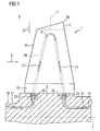
- FIG. 1 shows a rotor blade 1 attached to a rotor 3 of a gas turbine, not shown.
- the rotor blade 1 is one of a number of annularly arranged, radially extending in a flow channel 5 of the gas turbine turbine blades, which form in its entirety a blade stage, which in the annular cross section of the flow channel 5 extends.
- a variety of such annular blade stages is as well as the Flow channel arranged along an axis 7 of the gas turbine, not shown.
- the flow channel 5 is acted upon by a working fluid 9 in the form of a hot gas mixture, which relaxes under the drive of the moving blade 1 and thus emits its kinetic energy while rotating the rotor to drive a generator, not shown.
- the rotor blade 1 points toward the turbine blade end 29, along its blade axis 11 one after the other arranged on a platform portion 13, arranged in the form of a hollow profile blade 15 and arranged in the form of a hollow blade blade tip 17.
- the platform region 13 in this case comprises a blade platform for limiting the flow channel 5 and a blade root, which are not shown in detail.
- the blade 1 is as schematically indicated, acted upon via a channel system 19 with a cooling fluid 21.
- the cooling system 19 also has suitable dosing means 23 which can control the supply 25 of the cooling fluid 21 into the blade and which are indicated here only schematically by the reference numeral 23.
- the cooling of the blade 1 extends in particular to the blade 15 and the blade tip 17th
- FIG. 2 an embodiment of the design of the cooling system 19 in the region 27 between the blade 15 and the blade tip 17 is shown.
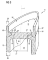
- FIG. 3 shows the embodiment according to the invention.
- the transition region 27 comprises in particular the airfoil 15 on its side facing the turbine blade end 29 of the turbine blade 1 and the blade tip 17 on its side facing away from the turbine blade end 29 of the rotor blade 1.
- FIG. 2 shows a blade according to the preamble of claim 1, wherein the blade and the blade tip are made separately 31 in the transition region 27 of FIG. 1 in a perspective sectional view.
- the rotor blade 31 has an airfoil 33 designed as a hollow profile and a blade tip 35 designed as a hollow profile.
- the hollow profile of the blade 33 in this case has a cavity 37 and the hollow profile of the blade tip 35 in this case has a cavity 39, the part of in FIG. 1 are shown cooling system 19 and can be acted upon with cooling fluid.
- the airfoil 33 has at its in FIG. 1 shown turbine blade end 29 of the turbine blade 31 side facing a transverse to the blade axis 11 extending first wall 41.
- the blade tip 35 has at its from the in FIG.
- the first wall 41 and the second wall 43 are opposed to form a double bottom 45.
- a cavity 47 is formed between the first wall 41 and the second wall 43, both of which extend horizontally over the entire cross section of the hollow profile.
- the double bottom 45 carries thereby cooling technical means, which are explained in detail below.
- the second wall 43 carries a number of swirling or turbulator elements in the form of nipples 49 and dimples 51.
- a nipple 49 is formed in the cavity 47 on the second wall 43.
- a dimple 51 expands the cavity 47 in the form of a recess in the second wall 43.
- the said swirling elements serve primarily to swirl a cooling fluid which flows through the impingement cooling openings 53 in the first Wall 41 can be supplied to the cavity 47.
- the impact cooling openings 53 are arranged perpendicular to the second wall 43.
- first wall 41 is arranged so close to the second wall 43, that a correspondingly pressurized cooling medium bounces on the second wall 43 via the impingement cooling openings 53 and the blade tip 35 effectively cools via the second web 43 in the context of impingement cooling.
- said turbulence elements in the form of nipples 49 and dimples 51 this illustrated impingement cooling is enhanced. That is, heat received in the blade tip is effectively dissipated by the cooling fluid.
- the second wall 43 has a first number of film cooling holes 55 and a second number of film cooling holes 57.
- a first film cooling opening 55 is aligned obliquely from the inside to the outside in the direction of the turbine blade end 29 of the turbine blade 31 and can thus afford a film of cooling fluid on the inner wall 59 of the blade tip 35 in a suitably gentle manner.
- An even more obliquely arranged second film cooling opening 57 makes it possible to produce a further film of cooling fluid on the outer wall 61 of the blade tip 35 via the same mechanism.
- the wall structure of the blade tip 35 has a wall thickness 63 which is smaller than the wall thickness 65 of the wall structure of the blade 33.
- the wall structure of the blade tip 35 has the same reason a higher porosity, not shown, than the wall structure of the airfoil 33.
- the double bottom 45 of the rotor blade 31, which comprises a cavity 47 is advantageously provided with cooling-technical means, which it allow to effectively cool the blade tip 35 and thus save cooling medium, which can increase the overall efficiency of a gas turbine.
- blade 31 advantageously produce in the context of a manufacturing process, which provides a separate casting process, and thus a separate production of the airfoil 33 on the one hand and the blade tip on the other. The separately cast blade tip 35 is then soldered to the separately cast airfoil 33 to form the double bottom 45 and the cavity 47.
- the particularly advantageous double bottom 45 with cavity 47 and cooling means can thus be particularly useful to achieve via a separate casting process for blade tip 35 and blade 33 as explained.
- the airfoil 33 can be cast from a different material than the blade tip 35.
- the airfoil 33 is expediently cast in terms of its greater mechanical stress of a high-strength material, while the blade tip 35 with respect to their higher thermal stress of a highly heat-conductive material , For example, a cobalt material is poured.
- a blade according to claim 1, is in FIG. 3 In particular, with a view to simplifying the manufacturing process in addition to the in FIG. 2 having shown blade further elements.
- the remaining features of FIG. 2 are in FIG. 3 provided with the same reference numerals.
- the airfoil 73 provides a core-holding bore 77 in the first wall 79, which in the present case is closed by a plug 81 in the second wall 83 of the blade tip 85 as soon as the separately prepared blade tip 85 and the separately manufactured airfoil 73 abut one another are joined. Because the here explained challenging geometry of the blade tip 85 does not have to be poured together with the blade 73, the cast of the blade 71 is simplified.
- the core holding hole 77 shown here which is available by casting, can be closed particularly reliably.
- the connection between the blade tip 85 and the blade 73 is in the present case produced by a particularly suitable welding method in the joining region 87.
- the connecting surfaces between blade tip 85 and blade 73 in the joining region 87 can be produced in a particularly simple and precise manner.
- the closure of the core holding hole 77 is carried out in the context of a specially measured fit of the plug 81 on the core holding hole 77th
- blade 31 Both at the in FIG. 2 shown blade 31 as well as in the FIG. 3 shown blade 71 can in a separate production of airfoil 33, 73 and blade tip 35, 85 relatively complex cooling means still in a relatively simple manner in a casting technology manufacturing process in the blade profile 31, 71 provide and thus a particularly efficient cooling of the blade tip 35, Reach 85.
- a turbine blade according to claim 1 is designed for more efficient cooling of a blade tip 85.
Landscapes
- Engineering & Computer Science (AREA)
- Mechanical Engineering (AREA)
- General Engineering & Computer Science (AREA)
- Turbine Rotor Nozzle Sealing (AREA)
Claims (9)
- Aube (71) de turbine ayant une lame (73) d'aube disposée sous la forme d'un profilé creux le long d'un axe 11 d'aube allant vers l'extrémité (29) de l'aube de turbine et une pointe (85) d'aube sous la forme d'un profilé creux,
dans laquelle la lame (73) d'aube a, à son extrémité tournée vers l'extrémité (29) d'aube de turbine, une première paroi (79) s'étendant dans le profilé creux transversalement à l'axe (11) de l'aube, et
la pointe (85) d'aube a, à son extrémité éloignée de l'extrémité (29) d'aube de turbine, une deuxième paroi (83) s'étendant dans le profilé creux transversalement à l'axe (11) de l'aube,
dans laquelle,
La première paroi (79) et la deuxième paroi (83) sont opposées en formant un fond (45) double portant un moyen de technique de refroidissement.
caractérisée,
en ce la pointe (85) d'aube et la lame (73) d'aube sont fabriquées séparément et
la deuxième paroi (83) a un moyen de fermeture d'un trou de retenu du noyau de la première paroi (41 79) - Aube (71) de turbine suivant la revendication 1, caractérisée en ce que le moyen de technique de refroidissement est un moyen choisi dans le groupe constitué d'un moyen à dispositif donnant une turbulence, d'un moyen de refroidissement par rebondissement et d'un moyen de refroidissement pelliculaire.
- Aube (71) de turbine suivant la revendication 1 ou 2, caractérisée en ce que pour former un moyen donnant une turbulence, la première paroi (79)et/ou la deuxième paroi (83) portent un certain nombre de mamelons, de bossages, de nervures, de rainures ou d'autres éléments de tourbillonnement.
- Aube (71) de turbine suivant l'une des revendications 1 à 3, caractérisée en ce que, pour former un moyen de refroidissement par rebondissement, la première paroi (79) porte un certain nombre d'ouvertures de refroidissement par rebondissement qui permettent de faire rebondir le fluide de refroidissement sur la deuxième paroi (83) lorsque l'aube (71) de turbine est alimentée en fluide de refroidissement.
- Aube (71) de turbine suivant l'une des revendications 1 à 4, caractérisée en ce que, pour former un moyen de refroidissement pelliculaire, la deuxième paroi (83)et/ou le profilé creux de la pointe (85) de l'aube porte un certain nombre d'ouvertures 55 de refroidissement pelliculaire qui permettent de produire une pellicule de fluide de refroidissement sur la structure de paroi de la pointe (85) d'aube lorsque l'aube (71) de turbine est alimentée en fluide de refroidissement.
- Aube (71) de turbine suivant l'une des revendications 1 à 5, caractérisé en ce que la structure de paroi de la pointe (85) d'aube à une porosité plus grande et/ou une épaisseur de paroi plus petite que la structure de paroi de la lame (73) d'aube.
- Aube (71) de turbine suivant les revendications 1 à 6, caractérisée en ce que la lame (73) d'aube et la pointe (85) d'aube sont fabriquées dans du matériau différent, la lame (73) d'aube étant coulée en un matériau très résistant et la pointe (85) d'aube étant fabriquée en un matériau très conducteur de la chaleur.
- Aube (71) de turbine suivant l'une des revendications 1 à 7, caractérisée en ce que la pointe (85) d'aube est assemblée à la lame (73) d'aube la pointe (85) d'aube et la lame (73) d'aube étant notamment brasée ou soudée.
- Turbine (1) à gaz ayant un canal (5) d'écoulement, s'étendant le long d'un axe (7) de la turbine (1) à gaz et de section transversale annulaire, pour l'alimentation en un fluide (9) de travail, un certain nombre d'étages d'aubes disposés le long de l'axe, un étage d'aubes ayant un certain nombre d'aubes (71) de turbine suivant l'une des revendications précédentes, disposées annulairement, s'étendant radialement dans le canal (5) et pouvant être alimentées en un fluide de refroidissement.
Priority Applications (2)
| Application Number | Priority Date | Filing Date | Title |
|---|---|---|---|
| DE200450006484 DE502004006484D1 (de) | 2004-01-23 | 2004-01-23 | Kühlung einer Turbinenschaufel mit einem Doppelboden zwischen Schaufelblatt und Schaufelspitze |
| EP20040001468 EP1557533B1 (fr) | 2004-01-23 | 2004-01-23 | Refroidissement d'une aube de turbine avec faux-plancher entre l'aube et son extrémité |
Applications Claiming Priority (1)
| Application Number | Priority Date | Filing Date | Title |
|---|---|---|---|
| EP20040001468 EP1557533B1 (fr) | 2004-01-23 | 2004-01-23 | Refroidissement d'une aube de turbine avec faux-plancher entre l'aube et son extrémité |
Publications (2)
| Publication Number | Publication Date |
|---|---|
| EP1557533A1 EP1557533A1 (fr) | 2005-07-27 |
| EP1557533B1 true EP1557533B1 (fr) | 2008-03-12 |
Family
ID=34626498
Family Applications (1)
| Application Number | Title | Priority Date | Filing Date |
|---|---|---|---|
| EP20040001468 Expired - Lifetime EP1557533B1 (fr) | 2004-01-23 | 2004-01-23 | Refroidissement d'une aube de turbine avec faux-plancher entre l'aube et son extrémité |
Country Status (2)
| Country | Link |
|---|---|
| EP (1) | EP1557533B1 (fr) |
| DE (1) | DE502004006484D1 (fr) |
Cited By (2)
| Publication number | Priority date | Publication date | Assignee | Title |
|---|---|---|---|---|
| US11208899B2 (en) | 2018-03-14 | 2021-12-28 | General Electric Company | Cooling assembly for a turbine assembly |
| US11512598B2 (en) | 2018-03-14 | 2022-11-29 | General Electric Company | Cooling assembly for a turbine assembly |
Families Citing this family (10)
| Publication number | Priority date | Publication date | Assignee | Title |
|---|---|---|---|---|
| US7175391B2 (en) * | 2004-07-08 | 2007-02-13 | United Technologies Corporation | Turbine blade |
| EP2426316A1 (fr) | 2010-09-03 | 2012-03-07 | Siemens Aktiengesellschaft | Pale de turbine |
| FR2983517B1 (fr) * | 2011-12-06 | 2013-12-20 | Snecma | Aube de turbine refroidie pour moteur a turbine a gaz. |
| DE102013224998A1 (de) * | 2013-12-05 | 2015-06-11 | Rolls-Royce Deutschland Ltd & Co Kg | Turbinenrotorschaufel einer Gasturbine und Verfahren zur Kühlung einer Schaufelspitze einer Turbinenrotorschaufel einer Gasturbine |
| EP3088673B1 (fr) * | 2015-04-28 | 2017-11-01 | Siemens Aktiengesellschaft | Aube rotorique de turbine à gaz, rotor, turbine à gaz et moteur associés |
| US10053992B2 (en) * | 2015-07-02 | 2018-08-21 | United Technologies Corporation | Gas turbine engine airfoil squealer pocket cooling hole configuration |
| US10801334B2 (en) * | 2018-09-12 | 2020-10-13 | Raytheon Technologies Corporation | Cooling arrangement with purge partition |
| CN114776387A (zh) * | 2022-05-06 | 2022-07-22 | 中国联合重型燃气轮机技术有限公司 | 透平动叶和燃气轮机 |
| CN115163203B (zh) * | 2022-06-24 | 2024-12-03 | 中国船舶重工集团公司第七0三研究所 | 一种具有空心叶冠结构的涡轮动叶 |
| CN121803307A (zh) * | 2026-03-10 | 2026-04-07 | 中国航发沈阳发动机研究所 | 一种高压涡轮导向叶片双层壁结构 |
Family Cites Families (8)
| Publication number | Priority date | Publication date | Assignee | Title |
|---|---|---|---|---|
| US3732031A (en) * | 1970-06-17 | 1973-05-08 | Gen Motors Corp | Cooled airfoil |
| GB2279705B (en) * | 1985-07-24 | 1995-06-28 | Rolls Royce Plc | Cooling of turbine blades for a gas turbine engine |
| JP2862536B2 (ja) * | 1987-09-25 | 1999-03-03 | 株式会社東芝 | ガスタービンの翼 |
| JP2693527B2 (ja) * | 1988-11-21 | 1997-12-24 | 株式会社東芝 | ターボ機械の動翼構造 |
| US5752802A (en) * | 1996-12-19 | 1998-05-19 | Solar Turbines Incorporated | Sealing apparatus for airfoils of gas turbine engines |
| US6135715A (en) * | 1999-07-29 | 2000-10-24 | General Electric Company | Tip insulated airfoil |
| US6164914A (en) * | 1999-08-23 | 2000-12-26 | General Electric Company | Cool tip blade |
| US6595748B2 (en) * | 2001-08-02 | 2003-07-22 | General Electric Company | Trichannel airfoil leading edge cooling |
-
2004
- 2004-01-23 DE DE200450006484 patent/DE502004006484D1/de not_active Expired - Lifetime
- 2004-01-23 EP EP20040001468 patent/EP1557533B1/fr not_active Expired - Lifetime
Cited By (2)
| Publication number | Priority date | Publication date | Assignee | Title |
|---|---|---|---|---|
| US11208899B2 (en) | 2018-03-14 | 2021-12-28 | General Electric Company | Cooling assembly for a turbine assembly |
| US11512598B2 (en) | 2018-03-14 | 2022-11-29 | General Electric Company | Cooling assembly for a turbine assembly |
Also Published As
| Publication number | Publication date |
|---|---|
| EP1557533A1 (fr) | 2005-07-27 |
| DE502004006484D1 (de) | 2008-04-24 |
Similar Documents
| Publication | Publication Date | Title |
|---|---|---|
| EP3191244B1 (fr) | Procédé de production d'une aube mobile et aube obtenue | |
| EP1834066B1 (fr) | Aube de turbine pour turbine a gaz, utilisation d'une aube de turbine et procede de refroidissement d'une aube de turbine | |
| DE1476796C3 (de) | Aus einem hochfesten Material integral hergestelltes Bauteil einer Gasturbinenanlage | |
| EP1113145B1 (fr) | Aube pour turbine a gaz avec section de mesure sur le bord de fuite | |
| DE69320203T2 (de) | Struktur für eine gekühlte schaufel | |
| DE60018817T2 (de) | Gekühlte Gasturbinenschaufel | |
| DE69317901T2 (de) | Verstärkte hinterkante für gusskern einer turbinenschaufel | |
| EP1557533B1 (fr) | Refroidissement d'une aube de turbine avec faux-plancher entre l'aube et son extrémité | |
| DE102008055590B4 (de) | Turbinenschaufel-Deckband | |
| DE102008002862A1 (de) | Stator-Rotor-Anordnung mit einem Oberflächenmerkmal zum verbesserten Einschluss des Gasstroms und verwandte Verfahren | |
| WO2007051733A1 (fr) | Turbine à gaz | |
| CH703876B1 (de) | Turbinenrotorschaufel mit Plattformkühlanordnung und Verfahren zu deren Herstellung. | |
| CH698339B1 (de) | Turbinenschaufel mit gekühltem Deckband. | |
| WO2011029420A1 (fr) | Dispositif de déflexion pour un écoulement de fuite dans une turbine à gaz et turbine à gaz correspondante | |
| DE10020673A1 (de) | Gehäusestruktur in Metallbauweise | |
| EP2881541A1 (fr) | Refroidissement de pointe d'aube d'un aube de rotor de turbine à gaz | |
| WO2017153219A1 (fr) | Aube mobile pour turbine à gaz avec bord de frottement refroidi | |
| DE102015213087A1 (de) | Schaufel für eine Strömungskraftmaschine und Verfahren zu deren Herstellung | |
| WO2016110387A1 (fr) | Composant de turbine à gaz refroidi par film | |
| EP1510653B1 (fr) | Aube de turbine refroidie | |
| DE102012213017A1 (de) | Verfahren zur Herstellung einer Turbinenschaufel | |
| WO2010028913A1 (fr) | Aube de turbine à bord de fuite étagé modulaire | |
| EP3023191A1 (fr) | Aube de turbine constituée de deux parties | |
| DE102009044584A1 (de) | Einrichtung in Zusammenhang mit Turbinenschaufelkühlöffnungen | |
| EP3029268A1 (fr) | Aube directrice de turbine |
Legal Events
| Date | Code | Title | Description |
|---|---|---|---|
| PUAI | Public reference made under article 153(3) epc to a published international application that has entered the european phase |
Free format text: ORIGINAL CODE: 0009012 |
|
| AK | Designated contracting states |
Kind code of ref document: A1 Designated state(s): AT BE BG CH CY CZ DE DK EE ES FI FR GB GR HU IE IT LI LU MC NL PT RO SE SI SK TR |
|
| AX | Request for extension of the european patent |
Extension state: AL LT LV MK |
|
| 17P | Request for examination filed |
Effective date: 20051219 |
|
| AKX | Designation fees paid |
Designated state(s): CH DE GB IT LI |
|
| GRAP | Despatch of communication of intention to grant a patent |
Free format text: ORIGINAL CODE: EPIDOSNIGR1 |
|
| GRAS | Grant fee paid |
Free format text: ORIGINAL CODE: EPIDOSNIGR3 |
|
| GRAA | (expected) grant |
Free format text: ORIGINAL CODE: 0009210 |
|
| AK | Designated contracting states |
Kind code of ref document: B1 Designated state(s): CH DE GB IT LI |
|
| REG | Reference to a national code |
Ref country code: GB Ref legal event code: FG4D Free format text: NOT ENGLISH |
|
| REG | Reference to a national code |
Ref country code: CH Ref legal event code: EP |
|
| REF | Corresponds to: |
Ref document number: 502004006484 Country of ref document: DE Date of ref document: 20080424 Kind code of ref document: P |
|
| REG | Reference to a national code |
Ref country code: CH Ref legal event code: NV Representative=s name: SIEMENS SCHWEIZ AG |
|
| PLBE | No opposition filed within time limit |
Free format text: ORIGINAL CODE: 0009261 |
|
| STAA | Information on the status of an ep patent application or granted ep patent |
Free format text: STATUS: NO OPPOSITION FILED WITHIN TIME LIMIT |
|
| 26N | No opposition filed |
Effective date: 20081215 |
|
| REG | Reference to a national code |
Ref country code: CH Ref legal event code: PCAR Free format text: SIEMENS SCHWEIZ AG;INTELLECTUAL PROPERTY FREILAGERSTRASSE 40;8047 ZUERICH (CH) |
|
| PGFP | Annual fee paid to national office [announced via postgrant information from national office to epo] |
Ref country code: IT Payment date: 20160127 Year of fee payment: 13 Ref country code: DE Payment date: 20160321 Year of fee payment: 13 |
|
| PGFP | Annual fee paid to national office [announced via postgrant information from national office to epo] |
Ref country code: GB Payment date: 20160111 Year of fee payment: 13 |
|
| PGFP | Annual fee paid to national office [announced via postgrant information from national office to epo] |
Ref country code: CH Payment date: 20160404 Year of fee payment: 13 |
|
| REG | Reference to a national code |
Ref country code: DE Ref legal event code: R119 Ref document number: 502004006484 Country of ref document: DE |
|
| REG | Reference to a national code |
Ref country code: CH Ref legal event code: PL |
|
| GBPC | Gb: european patent ceased through non-payment of renewal fee |
Effective date: 20170123 |
|
| PG25 | Lapsed in a contracting state [announced via postgrant information from national office to epo] |
Ref country code: LI Free format text: LAPSE BECAUSE OF NON-PAYMENT OF DUE FEES Effective date: 20170131 Ref country code: CH Free format text: LAPSE BECAUSE OF NON-PAYMENT OF DUE FEES Effective date: 20170131 |
|
| PG25 | Lapsed in a contracting state [announced via postgrant information from national office to epo] |
Ref country code: GB Free format text: LAPSE BECAUSE OF NON-PAYMENT OF DUE FEES Effective date: 20170123 Ref country code: DE Free format text: LAPSE BECAUSE OF NON-PAYMENT OF DUE FEES Effective date: 20170801 |
|
| PG25 | Lapsed in a contracting state [announced via postgrant information from national office to epo] |
Ref country code: IT Free format text: LAPSE BECAUSE OF NON-PAYMENT OF DUE FEES Effective date: 20170123 |