EP1557548B1 - Verfahren zum Betrieb einer gemischaufgeladenen Brennkraftmaschine - Google Patents
Verfahren zum Betrieb einer gemischaufgeladenen Brennkraftmaschine Download PDFInfo
- Publication number
- EP1557548B1 EP1557548B1 EP04027620A EP04027620A EP1557548B1 EP 1557548 B1 EP1557548 B1 EP 1557548B1 EP 04027620 A EP04027620 A EP 04027620A EP 04027620 A EP04027620 A EP 04027620A EP 1557548 B1 EP1557548 B1 EP 1557548B1
- Authority
- EP
- European Patent Office
- Prior art keywords
- cylinder
- fuel
- temperature
- internal combustion
- combustion engine
- Prior art date
- Legal status (The legal status is an assumption and is not a legal conclusion. Google has not performed a legal analysis and makes no representation as to the accuracy of the status listed.)
- Expired - Lifetime
Links
- 238000000034 method Methods 0.000 title claims description 21
- 239000000203 mixture Substances 0.000 title claims description 19
- 238000002485 combustion reaction Methods 0.000 claims description 26
- 239000000446 fuel Substances 0.000 claims description 17
- 239000000523 sample Substances 0.000 claims description 7
- 230000006698 induction Effects 0.000 claims 2
- 238000005474 detonation Methods 0.000 claims 1
- 230000001105 regulatory effect Effects 0.000 claims 1
- 239000007789 gas Substances 0.000 description 26
- 238000004200 deflagration Methods 0.000 description 13
- 238000005259 measurement Methods 0.000 description 4
- UFHFLCQGNIYNRP-UHFFFAOYSA-N Hydrogen Chemical compound [H][H] UFHFLCQGNIYNRP-UHFFFAOYSA-N 0.000 description 2
- 239000001257 hydrogen Substances 0.000 description 2
- 229910052739 hydrogen Inorganic materials 0.000 description 2
- VNWKTOKETHGBQD-UHFFFAOYSA-N methane Chemical compound C VNWKTOKETHGBQD-UHFFFAOYSA-N 0.000 description 2
- 238000009530 blood pressure measurement Methods 0.000 description 1
- 239000000571 coke Substances 0.000 description 1
- 230000003111 delayed effect Effects 0.000 description 1
- 230000000694 effects Effects 0.000 description 1
- 239000002360 explosive Substances 0.000 description 1
- 239000002737 fuel gas Substances 0.000 description 1
- 239000003502 gasoline Substances 0.000 description 1
- 230000017525 heat dissipation Effects 0.000 description 1
- 239000012535 impurity Substances 0.000 description 1
- 239000003345 natural gas Substances 0.000 description 1
- 230000002035 prolonged effect Effects 0.000 description 1
- 238000000197 pyrolysis Methods 0.000 description 1
- 230000002459 sustained effect Effects 0.000 description 1
- 208000024891 symptom Diseases 0.000 description 1
- 238000010792 warming Methods 0.000 description 1
Images



Classifications
-
- F—MECHANICAL ENGINEERING; LIGHTING; HEATING; WEAPONS; BLASTING
- F02—COMBUSTION ENGINES; HOT-GAS OR COMBUSTION-PRODUCT ENGINE PLANTS
- F02D—CONTROLLING COMBUSTION ENGINES
- F02D35/00—Controlling engines, dependent on conditions exterior or interior to engines, not otherwise provided for
- F02D35/02—Controlling engines, dependent on conditions exterior or interior to engines, not otherwise provided for on interior conditions
- F02D35/025—Controlling engines, dependent on conditions exterior or interior to engines, not otherwise provided for on interior conditions by determining temperatures inside the cylinder, e.g. combustion temperatures
-
- F—MECHANICAL ENGINEERING; LIGHTING; HEATING; WEAPONS; BLASTING
- F02—COMBUSTION ENGINES; HOT-GAS OR COMBUSTION-PRODUCT ENGINE PLANTS
- F02D—CONTROLLING COMBUSTION ENGINES
- F02D19/00—Controlling engines characterised by their use of non-liquid fuels, pluralities of fuels, or non-fuel substances added to the combustible mixtures
- F02D19/02—Controlling engines characterised by their use of non-liquid fuels, pluralities of fuels, or non-fuel substances added to the combustible mixtures peculiar to engines working with gaseous fuels
- F02D19/021—Control of components of the fuel supply system
- F02D19/023—Control of components of the fuel supply system to adjust the fuel mass or volume flow
-
- F—MECHANICAL ENGINEERING; LIGHTING; HEATING; WEAPONS; BLASTING
- F02—COMBUSTION ENGINES; HOT-GAS OR COMBUSTION-PRODUCT ENGINE PLANTS
- F02D—CONTROLLING COMBUSTION ENGINES
- F02D19/00—Controlling engines characterised by their use of non-liquid fuels, pluralities of fuels, or non-fuel substances added to the combustible mixtures
- F02D19/02—Controlling engines characterised by their use of non-liquid fuels, pluralities of fuels, or non-fuel substances added to the combustible mixtures peculiar to engines working with gaseous fuels
- F02D19/025—Failure diagnosis or prevention; Safety measures; Testing
-
- F—MECHANICAL ENGINEERING; LIGHTING; HEATING; WEAPONS; BLASTING
- F02—COMBUSTION ENGINES; HOT-GAS OR COMBUSTION-PRODUCT ENGINE PLANTS
- F02D—CONTROLLING COMBUSTION ENGINES
- F02D19/00—Controlling engines characterised by their use of non-liquid fuels, pluralities of fuels, or non-fuel substances added to the combustible mixtures
- F02D19/02—Controlling engines characterised by their use of non-liquid fuels, pluralities of fuels, or non-fuel substances added to the combustible mixtures peculiar to engines working with gaseous fuels
- F02D19/026—Measuring or estimating parameters related to the fuel supply system
-
- F—MECHANICAL ENGINEERING; LIGHTING; HEATING; WEAPONS; BLASTING
- F02—COMBUSTION ENGINES; HOT-GAS OR COMBUSTION-PRODUCT ENGINE PLANTS
- F02D—CONTROLLING COMBUSTION ENGINES
- F02D41/00—Electrical control of supply of combustible mixture or its constituents
- F02D41/0002—Controlling intake air
- F02D41/0007—Controlling intake air for control of turbo-charged or super-charged engines
-
- F—MECHANICAL ENGINEERING; LIGHTING; HEATING; WEAPONS; BLASTING
- F02—COMBUSTION ENGINES; HOT-GAS OR COMBUSTION-PRODUCT ENGINE PLANTS
- F02D—CONTROLLING COMBUSTION ENGINES
- F02D41/00—Electrical control of supply of combustible mixture or its constituents
- F02D41/0025—Controlling engines characterised by use of non-liquid fuels, pluralities of fuels, or non-fuel substances added to the combustible mixtures
- F02D41/0027—Controlling engines characterised by use of non-liquid fuels, pluralities of fuels, or non-fuel substances added to the combustible mixtures the fuel being gaseous
-
- F—MECHANICAL ENGINEERING; LIGHTING; HEATING; WEAPONS; BLASTING
- F02—COMBUSTION ENGINES; HOT-GAS OR COMBUSTION-PRODUCT ENGINE PLANTS
- F02D—CONTROLLING COMBUSTION ENGINES
- F02D2200/00—Input parameters for engine control
- F02D2200/02—Input parameters for engine control the parameters being related to the engine
- F02D2200/10—Parameters related to the engine output, e.g. engine torque or engine speed
- F02D2200/1002—Output torque
-
- F—MECHANICAL ENGINEERING; LIGHTING; HEATING; WEAPONS; BLASTING
- F02—COMBUSTION ENGINES; HOT-GAS OR COMBUSTION-PRODUCT ENGINE PLANTS
- F02D—CONTROLLING COMBUSTION ENGINES
- F02D41/00—Electrical control of supply of combustible mixture or its constituents
- F02D41/02—Circuit arrangements for generating control signals
- F02D41/14—Introducing closed-loop corrections
- F02D41/1438—Introducing closed-loop corrections using means for determining characteristics of the combustion gases; Sensors therefor
- F02D41/1444—Introducing closed-loop corrections using means for determining characteristics of the combustion gases; Sensors therefor characterised by the characteristics of the combustion gases
- F02D41/1446—Introducing closed-loop corrections using means for determining characteristics of the combustion gases; Sensors therefor characterised by the characteristics of the combustion gases the characteristics being exhaust temperatures
-
- Y—GENERAL TAGGING OF NEW TECHNOLOGICAL DEVELOPMENTS; GENERAL TAGGING OF CROSS-SECTIONAL TECHNOLOGIES SPANNING OVER SEVERAL SECTIONS OF THE IPC; TECHNICAL SUBJECTS COVERED BY FORMER USPC CROSS-REFERENCE ART COLLECTIONS [XRACs] AND DIGESTS
- Y02—TECHNOLOGIES OR APPLICATIONS FOR MITIGATION OR ADAPTATION AGAINST CLIMATE CHANGE
- Y02T—CLIMATE CHANGE MITIGATION TECHNOLOGIES RELATED TO TRANSPORTATION
- Y02T10/00—Road transport of goods or passengers
- Y02T10/10—Internal combustion engine [ICE] based vehicles
- Y02T10/12—Improving ICE efficiencies
-
- Y—GENERAL TAGGING OF NEW TECHNOLOGICAL DEVELOPMENTS; GENERAL TAGGING OF CROSS-SECTIONAL TECHNOLOGIES SPANNING OVER SEVERAL SECTIONS OF THE IPC; TECHNICAL SUBJECTS COVERED BY FORMER USPC CROSS-REFERENCE ART COLLECTIONS [XRACs] AND DIGESTS
- Y02—TECHNOLOGIES OR APPLICATIONS FOR MITIGATION OR ADAPTATION AGAINST CLIMATE CHANGE
- Y02T—CLIMATE CHANGE MITIGATION TECHNOLOGIES RELATED TO TRANSPORTATION
- Y02T10/00—Road transport of goods or passengers
- Y02T10/10—Internal combustion engine [ICE] based vehicles
- Y02T10/30—Use of alternative fuels, e.g. biofuels
Definitions
- the present invention relates to a method for operating a mixture-charged internal combustion engine having at least one intake tract via the fuel-air mixture is supplied to at least one cylinder and an exhaust tract. Moreover, the invention relates to an internal combustion engine with a control device for carrying out the method.
- combustion-induced deflagrations are the main cause of combustion of process exhaust gases.
- process emissions since they often contain a high proportion of impurities, which are deposited in the combustion chamber of the engine compared to pure natural gas. The thicker the deposits become, the worse the heat dissipation to the cylinder wall, which leads to a strong warming. If the surface temperature of the deposits rises above the ignition temperature of the incoming fuel-air mixture, the mixture is ignited even before the actual ignition.
- Object of the present invention is to provide a method and a control device for an internal combustion engine, so as to avoid the described, caused by glow ignition deflagration in the intake.
- the control device of the internal combustion engine already reacts to the symptoms of prolonged glow ignition and can prevent deflagration by appropriate interventions in the energy flow.
- the method consists essentially of two individual functions, a rapid reduction in power to a defined value and a brief interruption of the gas supply by closing valves in the fuel or fuel-air mixture supply line.
- a particular advantage of this method is that the engine does not usually need to be shut down to stop the glow ignitions.
- An internal combustion engine with a control for carrying out the method according to the invention has at least one temperature probe for measuring the temperature in the cylinder or in the downstream exhaust tract and at least one device for detecting the actual power.
- the internal combustion engine is preferably a mixture-charged, preferably stationary, Otto gas engine.
- Fig. 1 first shows the problem, as occurs in the prior art, based on the parameter motor actual power 1 and the temperature curves 2 and 3 plotted against the time t.
- Curve 2 shows the temperature profile measured by the temperature probes 17 in the exhaust gas tract of the cylinder concerned.
- the temperature profile of the fuel-air mixture in the intake tract is referenced by the reference numeral 3. If a sustained ignition in a cylinder 4 occurs, the engine experiences a Power dip, as can be seen on the course of the curve 1 in the area 1 '.
- the known in the prior art power regulator 7 react by opening the throttle valve 15 and / or by increasing the boost pressure at the boost pressure controller 13. This achieves the engine after a short time again its target power, as shown on the curve 1 in Fig. 1 can also be seen.
- FIG. 2 illustrated engine schematics of an embodiment of an internal combustion engine according to the invention.
- the internal combustion engine according to Fig. 2 has a plurality of cylinders 4 and a turbocharger 12, a throttle valve 15 with actuator 16, a wastegate 13 with actuator 14 and a gas mixer 10 with actuator 11.
- the fuel is supplied via a double gas supply line 35, in each of which a gas valve 9 is installed.
- the fuel gas is supplied to the gas mixer 10 with its actuator 11 and mixed with the sucked through the line 36 air in the desired mixing ratio.
- a power regulator 7 is provided which compares the detected by the device 5 actual power 1 with the target power 6 and correspondingly controls the actuators 16 and / or 14 of the throttle valve 15 and / or the boost pressure regulator 13.
- the actual power 1 of the entire internal combustion engine is measured integrally.
- a cylinder-selective actual power measurement for example by measuring the torsional vibration, crankshaft or by a pressure measurement in the cylinder 4 is possible.
- the control device 8 immediately reduces the target power 6, for example by rapid adjustment of the throttle valve 15 or the boost pressure at the boost pressure regulator 13. This is shown in the curve 3 Time of deflagration 3 'delayed and time gained.
- the arranged in the embodiment shown in the exhaust duct 37 of each cylinder temperature probes 17 measure the temperature profile 2 in the exhaust gas. This measurement can also be cylinder-selective (as shown) or integral for the internal combustion engine. Alternatively, a measurement of the cylinder temperature directly on the wall or the like is conceivable. Recognizes the control device measured by at least one probe 17 further increasing temperature according to curve 2 in Fig.
- the gas valves 9 are briefly closed when the cylinder or exhaust gas temperature 2 has risen above a critical value.
- this critical value is formed by relations to the mean of all cylinder temperatures in cylinder-selective measurement.
- Fig. 3 shows a measuring example for the application of the method according to the invention.
- Dashed line 3 shows the mixture temperature in the intake system.
- the solid line 2 in turn shows the exhaust gas temperature measured by the probes 17.
- the actual power 1 solid line
- the target power 6 shown dotted
- the target power 6 is initially reduced by the control device 8 immediately.
- the actual power 1 follows this run with some time delay. Due to the power reduction time is gained to respond to the increase in the temperature 2 in the exhaust system by closing the gas valves 9 in the time interval t1.
- Fig. 4 shows a supplemented by a third measure variant of the invention. This works first analogous to that of the basis of Fig. 3 illustrated process flow.
- the actual power 1 is reacted to the power dip 1 'by immediate reduction of the desired power 6 and closing of the gas valves 9 in the time range t1.
- these measures are not sufficient to reduce the temperature T in the exhaust or in the cylinder 2 back to the normal level. Instead, the measured temperature 2 continues to rise.
- it is provided according to this variant of the invention upon reaching a predefined maximum value of the cylinder or exhaust gas temperature 2, to completely close the gas valves 9 in order to shut off the engine.
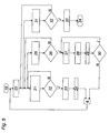
- Fig. 5 shows a control scheme according to the invention. Following the start 19, the target power 6 of the internal combustion engine is approached at point 20. At point 21, a comparison of the start and end signals of the actual power 1 takes place within a certain time window. If the power difference ascertained exceeds a predefined value, a power dip 1 'is detected. The controller responds by decision 22 with a rapid power reduction 23, resulting in a time delay 24 caused thereby. If the detected power difference remains below the critical mark, the control loop returns to the beginning of the point 21 again.
- the temperature 2 measured in the exhaust tract 37 is compared with a guideline value in step 25.
- This guide value can be, for example, the mean value of the exhaust-gas temperatures measured cylinder-selectively at the cylinders 4.
- step 26 it is decided whether or not the temperature difference detected in the comparison 25 exceeds a critical value. If it exceeds it, then it comes in point 27 for a brief interruption of the fuel supply or to close the gas valves 9.
- the step 28 reduces the target power after the reopening of the gas valves. Conveniently, in this power reduction, a fixed power value is approached to prevent unstable conditions in the engine or a swinging of the engine power.
- Step 29 causes a time delay until the next step.
- a third control string provided. This begins again at point 31 with the comparison of the measured with the probes 17 exhaust gas or cylinder temperature 2 with a guideline. For example, this can again be the average of all cylinder-specific cylinder temperatures or exhaust gas temperatures. If it is determined in point 32 that the deviation of the temperature 2 of a cylinder from the standard value exceeds a predefined maximum value of the deviation, then at point 33, the entire internal combustion engine shuts off and thus the engine stops (point 34). If the difference between the selectively determined cylinder temperatures and the guide value does not exceed the predefined maximum value of the deviation, the control scheme follows, starting from point 32, the path N.
- the invention is not limited to the exemplary embodiments shown.
- the fuel supply is not interrupted simultaneously for all cylinders but cylinder-selectively. This can be done, for example, by closing the intake valves of individual cylinders.
Landscapes
- Engineering & Computer Science (AREA)
- Chemical & Material Sciences (AREA)
- Combustion & Propulsion (AREA)
- Mechanical Engineering (AREA)
- General Engineering & Computer Science (AREA)
- Health & Medical Sciences (AREA)
- Biomedical Technology (AREA)
- Output Control And Ontrol Of Special Type Engine (AREA)
- Electrical Control Of Air Or Fuel Supplied To Internal-Combustion Engine (AREA)
- Combined Controls Of Internal Combustion Engines (AREA)
Description
- Die vorliegende Erfindung betrifft ein Verfahren zum Betrieb einer gemischaufgeladenen Brennkraftmaschine mit mindestens einem Ansaugtrakt über den Brennstoff-Luft-Gemisch mindestens einem Zylinder zugeführt wird und einem Abgastrakt. Darüber hinaus betrifft die Erfindung eine Brennkraftmaschine mit einer Regeleinrichtung zur Durchführung des Verfahrens.
- Bei gemischaufgeladenen Brennkraftmaschinen kommt es vor allem bei Verbrennung von Prozessabgasen zu durch Glühzündungen hervorgerufenen ansaugseitigen Verpuffungen. Besonders kritisch sind hierbei Prozessabgase, da sie im Vergleich zu reinem Erdgas oft einen hohen Anteil an Verunreinigungen enthalten, die sich im Brennraum des Motors ablagern. Je dicker die Ablagerungen werden, umso schlechter funktioniert die Wärmeableitung an die Zylinderwand, was zu einer starken Erwärmung führt. Wenn die Oberflächentemperatur der Ablagerungen über die Entzündungstemperatur des einströmenden Brennstoff-Luft-Gemisches steigt, wird das Gemisch bereits vor dem eigentlichen Zündzeitpunkt entzündet.
- Wenn es durch die heißen Ablagerungen zu einem anhaltenden Frühzünden des einströmenden Gemisches an den heißen Zylinderwänden kommt, entsteht ein für den Motor kritischer Zustand. Es bricht die Leistung um einen einem Zylinder entsprechenden Anteil ein. Durch eine Gemischentzündung bei noch geöffneten Einlassventilen kommt es zur Verpuffung im Ansaugtrakt. Zwischen dem Beginn des dauerhaften Glühzündens und einer Rückzündung in den Ansaugtakt vergehen nur wenige Sekunden. Das geschilderte Phänomen wird zum Beispiel bei Brennstoffen mit wasserstoffhaltigen Gasen, wie Pyrolyseoder Koksgas beobachtet, da sich der Wasserstoff im Gemisch bei Auftreten irgendwelcher Zündquellen im System sehr zündfreudig verhält.
- Aufgabe der vorliegenden Erfindung ist es, ein Verfahren wie auch eine Regeleinrichtung für eine Brennkraftmaschine zu schaffen, um damit die geschilderten, durch Glühzündung hervorgerufenen Verpuffungen im Ansaugtrakt zu vermeiden.
- Dies wird erfindungsgemäß erreicht, indem - zur Verhinderung von durch Glühzündungen hervorgerufenen Verpuffungen im Ansaugtrakt - die Ist-Leistung der Brennkraftmaschine und die Temperatur im Zylinder oder im nachgeschalteten Abgastrakt gemessen werden und im Falle eines Leistungseinbruches der Ist-Leistung die Soll-Leistung der Brennkraftmaschine reduziert wird und anschließend bei weiter steigender Temperatur im Zylinder oder im nachgeschalteten Abgastrakt die Brennstoffzufuhr oder Brennstoff-Luft-Gemisch-Zufuhr kurzzeitig unterbrochen wird.
- Beim erfindungsgemäßen Verfahren reagiert die Regeleinrichtung der Brennkraftmaschine bereits auf die Symptome der anhaltenden Glühzündung und kann durch entsprechende Eingriffe in den Energiefluss eine Verpuffung verhindern. In der erfindungsgemäßen Grundvariante setzt sich das Verfahren im Wesentlichen aus zwei Einzelfunktionen zusammen, einer schnellen Leistungsreduktion auf einen definierten Wert und einem kurzzeitigen Unterbrechen der Gaszufuhr durch Sicherheitsschließen von Ventilen in der Brennstoff- oder Brennstoff-Luft-Gemisch-Zuleitung. Ein besonderer Vorteil dieses Verfahrens ist es, dass der Motor in der Regel nicht abgeschaltet werden muss, um die Glühzündungen zu stoppen.
- Eine Brennkraftmaschine mit einer Regelung zur Durchführung des erfindungsgemäßen Verfahrens weist mindestens eine Temperatursonde zur Messung der Temperatur im Zylinder oder im nachgeschalteten Abgastrakt und mindestens eine Einrichtung zur Erfassung der Ist-Leistung auf. Bei der Brennkraftmaschine handelt es sich vorzugsweise um einen gemischaufgeladenen, vorzugsweise stationären, Otto-Gas-Motor.
- Weitere Einzelheiten und Merkmale der vorliegenden Erfindung ergeben sich aus der nachfolgenden Figurenbeschreibung. Dabei zeigt:
- Fig. 1
- das Phänomen der durch Glühzündung verursachten Verpuffung im Ansaugtrakt anhand dreier gemessener Parameter,
- Fig. 2
- eine schematische Darstellung einer erfindungsgemäßen Brennkraftmaschine,
- Fig. 3 und 4
- die Wirkungen verschiedener Varianten des erfindungemäßen Verfahrens anhand ausgewählter Motorparameter und
- Fig. 5
- ein erfindungsgemäßes Regelschema.
-
Fig. 1 zeigt zunächst das Problem, wie es beim Stand der Technik auftritt, anhand der Parameter Motor-Ist-Leistung 1 sowie der Temperaturverläufe 2 und 3 aufgetragen gegen die Zeit t. Die Kurve 2 zeigt dabei den von den Temperatursonden 17 im Abgastrakt des betroffenen Zylinders gemessenen Temperaturverlauf. Der Temperaturverlauf des Brennstoff-Luft-Gemisches im Ansaugtrakt ist mit dem Bezugszeichen 3 referenziert. Tritt eine anhaltende Glühzündung in einem Zylinder 4 auf, so erfährt der Motor einen Leistungseinbruch, wie er am Verlauf der Kurve 1 im Bereich 1' zu erkennen ist. Die beim Stand der Technik bekannten Leistungsregler 7 reagieren durch Öffnen der Drosselklappe 15 und/oder durch Erhöhung des Ladedrucks am Ladedruckregler 13. Hierdurch erreicht der Motor nach kurzer Zeit wieder seine Soll-Leistung, wie dies am Kurvenverlauf 1 inFig. 1 auch zu erkennen ist. Beim Stand der Technik steigt im Anschluss daran ohne eine weitere Beeinflussung der Motorleistung jedoch die Zylindertemperatur 2 weiter an. Bei einem gewissen Temperaturwert kommt es dann zu einer Verpuffung im Ansaugtrakt des Motors. Diese Verpuffung ist am im Ansaugtrakt gemessenen Temperaturverlauf 3 des Brennstoff-Luft-Gemisches gut erkennbar an dem sprunghaften Anstieg 3' der Gemischtemperatur 3. Die inFig. 1 gezeigten Verläufe 1, 2 und 3 zeigen reale Messdaten. In den meisten Fällen tritt die Verpuffung umso früher ein, je höher die Leistung ist. - Mit dem erfindungsgemäßen Verfahren wird nun an zwei Stellen, nämlich bei der Leistungsregelung und bei der Brennstoffzufuhr bzw. bei der Brennstoff-Luft-Gemisch-Zufuhr eingegriffen. Dieser Eingriff wird zunächst anhand des in
Fig. 2 dargestellten Motorschemas einer erfindungsgemäßen Ausführungsvariante einer Brennkraftmaschine beschrieben. Die Brennkraftmaschine gemäßFig. 2 weist mehrere Zylinder 4 sowie einen Turbolader 12, eine Drosselklappe 15 mit Stellglied 16, einen Ladedruckregler 13 mit Stellglied 14 und einen Gasmischer 10 mit Stellglied 11 auf. Im gezeigten Ausführungsbeispiel handelt es sich um einen gemischaufgeladenen stationären Otto-Gas-Motor. Die Brennstoffzufuhr erfolgt über eine doppelte Gaszuleitung 35, in welche jeweils ein Gasventil 9 eingebaut ist. Von dort wird das Brenngas dem Gasmischer 10 mit seinem Stellglied 11 zugeführt und mit der durch die Leitung 36 angesaugten Luft im gewünschten Mischungsverhältnis gemischt. Darüber hinaus ist ein Leistungsregler 7 vorgesehen, der die von der Einrichtung 5 erfasste Ist-Leistung 1 mit der Soll-Leistung 6 vergleicht und entsprechend die Stellglieder 16 und/oder 14 der Drosselklappe 15 und/oder des Ladedruckreglers 13 ansteuert. Im gezeigten Ausführungsbeispiel wird die Ist-Leistung 1 der gesamten Brennkraftmaschine integral gemessen. Alternativ ist aber auch eine zylinderselektive Ist-Leistungsmessung, zum Beispiel durch Messung der Torsionsschwingung, Kurbelwelle oder durch eine Druckmessung im Zylinder 4 möglich. - Wird von der Einrichtung 5 ein in
Fig. 1 dargestellter, durch Glühzündung hervorgerufener Leistungseinbruch 1' detektiert, so verringert die erfindungsgemäße Regeleinrichtung 8 sofort die Soll-Leistung 6, zum Beispiel durch schnelle Verstellung der Drosselklappe 15 oder des Ladedrucks am Ladedruckregler 13. Hierdurch wird der in der Kurve 3 gezeigte Zeitpunkt der Verpuffung 3' verzögert und Zeit gewonnen. Die im gezeigten Ausführungsbeispiel im Abgastrakt 37 jedes Zylinders angeordneten Temperatursonden 17 messen den Temperaturverlauf 2 im Abgas. Auch diese Messung kann zylinderselektiv (wie dargestellt) oder integral für die Brennkraftmaschine erfolgen. Alternativ ist auch eine Messung der Zylindertemperatur direkt an dessen Wandung oder dergleichen denkbar. Erkennt die Regeleinrichtung eine von zumindest einer Sonde 17 gemessene weiter steigende Temperatur gemäß Kurve 2 inFig. 1 , so werden die Gasventile 9 kurzzeitig geschlossen, wenn die Zylinder- bzw. Abgastemperatur 2 über einen kritischen Wert gestiegen ist. Vorzugsweise wird dieser kritische Wert durch Relationen zum Mittelwert aller Zylindertemperaturen bei zylinderselektiver Messung gebildet. Durch das kurzzeitige Ausschalten der Gaszufuhr wird die Glühzündung in dem betreffenden Zylinder gelöscht. Da es sich in der Regel um nur leicht anhaftende Ablagerungen handelt, welche zur Glühzündung führen, reicht die erfindungsgemäße Vorgehensweise, Leistungsreduktion mit kombinierter kurzzeitiger Schließung der Brennstoffzufuhr in der Regel aus, um das Phänomen der Glühzündung unter Kontrolle zu behalten. Nach Beendigung der Unterbrechung der Brennstoffzufuhr wird die Soll-Leistung von der Regeleinrichtung 8 zunächst auf einem vorab definierten niedrigen Niveau gehalten und erst beim Unterschreiten eines gewissen Temperaturwertes der Abgas- oder Zylindertemperatur 2 wird die Soll-Leistung 6 wieder erhöht. -
Fig. 3 zeigt ein Messbeispiel für die Anwendung des erfindungsgemäßen Verfahrens. Gestrichelt dargestellt ist der Verlauf 3 der Gemischtemperatur im Ansaugtrakt. Die durchgezogen dargestellte Linie 2 zeigt wiederum die Abgastemperatur gemessen durch die Sonden 17. Unterhalb der Temperaturverläufe sind die Ist-Leistung 1 (durchgezogene Linie) und die Soll-Leistung 6 (gepunktet dargestellt) gegen die Zeit t aufgetragen. Im Anschluss an einen Einbruch 1' der Ist-Leistung 1 wird die Soll-Leistung 6 von der Regeleinrichtung 8 zunächst sofort reduziert. Die Ist-Leistung 1 folgt mit etwas Zeitverzögerung diesem Lauf. Durch die Leistungsreduktion wird Zeit gewonnen, auf den Anstieg der Temperatur 2 im Abgastrakt durch Schließen der Gasventile 9 im Zeitintervall t1 zu reagieren. Wie am weiteren Verlauf der Kurve 2 zu erkennen ist, sinkt durch diese Maßnahme die Zylinder- bzw. Abgastemperatur 2 wieder auf normale Betriebswerte ab. Eine Verpuffung im Ansaugtrakt ist verhindert, wie dies am Temperaturverlauf 3 (Temperatur im Ansaugtrakt) zu erkennen ist. Das Schließen und wieder Öffnen der Gasventile 9 ist am Verlauf der Kurven 18 zu erkennen. -
Fig. 4 zeigt eine durch eine dritte Maßnahme ergänzte Variante der Erfindung. Diese funktioniert zunächst analog wie der anhand vonFig. 3 illustrierte Verfahrensablauf. Auch hier wird auf den Leistungseinbruch 1' der Ist-Leistung 1 durch unmittelbare Reduktion der Soll-Leistung 6 und Schließen der Gasventile 9 im Zeitbereich t1 reagiert. Im dargestellten Beispiel inFig. 4 reichen diese Maßnahmen jedoch ausnahmsweise nicht dazu aus, die Temperatur T im Abgas- bzw. im Zylinder 2 wieder auf das normale Niveau zu reduzieren. Anstelle dessen steigt die gemessene Temperatur 2 weiter an. Um nun eine Verpuffung im Ansaugtrakt zu verhindern, ist gemäß dieser Variante der Erfindung vorgesehen, bei Erreichen eines vorab definierten Maximalwertes der Zylinder- bzw. Abgastemperatur 2 die Gasventile 9 vollständig zu schließen um den Motor dadurch abzustellen. Bei dieser Art der Sicherheitsabstellung wird im Gegensatz zur normalen Abstellung des Motors der Ansaugtrakt sofort mit Luft gefüllt, sodass er kein explosionsfähiges Gemisch mehr enthält. Wie der Verlauf 3 der Temperatur im Ansaugtrakt zeigt, kommt es zu keiner Verpuffung des Brennstoff-Luft-Gemisches im Ansaugtrakt. -
Fig. 5 zeigt ein erfindungsgemäßes Regelschema. Im Anschluss an den Start 19 wird im Punkt 20 die Soll-Leistung 6 der Brennkraftmaschine angefahren. In Punkt 21 findet ein Vergleich des Anfangs- und Endsignals der Ist-Leistung 1 innerhalb eines bestimmten Zeitfensters statt. Übersteigt die dabei festgestellte Leistungsdifferenz einen vorab definierten Wert, so wird ein Leistungseinbruch 1' detektiert. Die Regelung reagiert durch die Entscheidung 22 mit einer schnellen Leistungsreduktion 23, was zu einer dadurch hervorgerufenen Zeitverzögerung 24 führt. Bleibt die detektierte Leistungsdifferenz unterhalb der kritischen Marke, so kehrt die Regelschleife wieder an den Anfang des Punktes 21 zurück. - In einem zweiten Regelstrang wird die im Abgastrakt 37 gemessene Temperatur 2 im Schritt 25 mit einem Richtwert verglichen. Dieser Richtwert kann zum Beispiel der Mittelwert der an den Zylindern 4 zylinderselektiv gemessenen Abgastemperaturen sein. Im Schritt 26 wird entschieden, ob die beim Vergleich 25 festgestellte Temperaturdifferenz einen kritischen Wert überschreitet oder nicht. Überschreitet sie ihn, so kommt es im Punkt 27 zum kurzzeitigen Unterbrechen der Brennstoffzufuhr bzw. zum Schließen der Gasventile 9. Der Schritt 28 reduziert die Sollleistung nach dem Wiederöffnen der Gasventile. Günstigerweise wird bei dieser Leistungsreduktion ein fixer Leistungswert angefahren um instabile Zustände im Motor bzw. ein Schwingen der Motorleistung zu verhindern. Schritt 29 veranlasst eine Zeitverzögerung bis zum nächsten Schritt. Im Anschluss daran wird im Punkt 30 überprüft, ob durch das kurzzeitige Unterbrechen der Brennstoffzufuhr die Glühzündung gelöscht wurde und die Temperatur 2 nicht mehr im kritischen Maß vom Richtwert abweicht. Wird eine überkritische Temperaturdifferenz festgestellt, so kehrt das Regelschema zum Punkt 27 zurück. Es wird durch ein weiteres kurzzeitiges Unterbrechen der Brennstoffzufuhr nochmals versucht, die Glühzündung zu löschen. Wird im Punkt 30 keine kritische Temperaturdifferenz festgestellt, so folgt das Regelschema dem Weg N.
- In der anhand von
Fig. 4 illustrierten optionalen Variante ist noch ein dritter Regelstrang vorgesehen. Dieser beginnt im Punkt 31 wieder mit dem Vergleich der mit den Sonden 17 gemessenen Abgas- bzw. Zylindertemperatur 2 mit einem Richtwert. Dieser kann zum Beispiel wieder der Mittelwert aller zylinderselektiv bestimmten Zylindertemperaturen oder Abgastemperaturen sein. Wird im Punkt 32 festgestellt, dass die Abweichung der Temperatur 2 eines Zylinders vom Richtwert einen vorab definierten Maximalwert der Abweichung überschreitet, kommt es im Punkt 33 zum Sicherheitsabstellen der gesamten Brennkraftmaschine und damit zum Motorstop (Punkt 34). Überschreitet die Differenz zwischen den selektiv bestimmten Zylindertemperaturen und dem Richtwert nicht den vorab vorgegebenen Maximalwert der Abweichung, folgt das Regelschema, ausgehend von Punkt 32, dem Weg N. - Die Erfindung ist nicht auf die gezeigten Ausführungsbeispiele beschränkt. So kann zum Beispiel vorgesehen sein, dass die Brennstoffzufuhr nicht gleichzeitig für alle Zylinder sondern zylinderselektiv unterbrochen wird. Dies kann zum Beispiel durch Schließen der Einlassventile einzelner Zylinder erfolgen.
Claims (7)
- Verfahren zum Betrieb einer gemischaufgeladenen Brennkraftmaschine mit mindestens einem Ansaugtrakt über den Brennstoff-Luft-Gemisch mindestens einem Zylinder zugeführt wird und einem Abgastrakt, dadurch gekennzeichnet, dass - zur Verhinderung von durch Glühzündungen hervorgerufenen Verpuffungen im Ansaugtrakt (37) - die Ist-Leistung (1) der Brennkraftmaschine und die Temperatur (2) im Zylinder oder im nachgeschalteten Abgastrakt (38) gemessen werden und im Falle eines Leistungseinbruches (1') der Ist-Leistung (1) die Soll-Leistung (6) der Brennkraftmaschine reduziert wird und anschließend bei weiter steigender Temperatur (2) im Zylinder oder im nachgeschalteten Abgastrakt (38) die Brennstoffzufuhr oder Brennstoff-Luft-Gemisch-Zufuhr kurzzeitig unterbrochen wird.
- Verfahren nach Anspruch 1, dadurch gekennzeichnet, dass nach Beendigung der Unterbrechung der Brennstoffzufuhr die Soll-Leistung (6) auf einem vorab definierten niedrigen Niveau gehalten und erst bei Erreichen eines gewissen Temperaturwertes (2) im Zylinder oder im Abgastrakt wieder erhöht wird.
- Verfahren nach Anspruch 1 oder 2 dadurch gekennzeichnet, dass im Anschluss an das Beenden der Unterbrechung der Brennstoffzufuhr und bei weiter steigender Temperatur im Zylinder oder im nachgeschalteten Abgastrakt über einen vorgebbaren Wert die Brennkraftmaschine oder zumindest ein Zylinder (4) abgeschaltet wird, wobei vorzugsweise die Brennstoffzufuhr oder Brennstoff-Luft-Gemisch-Zufuhr vollständig unterbrochen wird.
- Verfahren nach einem der Ansprüche 1 bis 3, dadurch gekennzeichnet, dass die Brennstoffzufuhr durch Schließen mindestens eines Ventils (9) in mindestens einer Brennstoffzufuhrleitung (35) oder zylinderselektiv, vorzugsweise durch Schließen mindestens eines Einlassventils, mindestens eines Zylinders (4), unterbrochen wird.
- Verfahren nach einem der Ansprüche 1 bis 4, dadurch gekennzeichnet, dass anstelle der Ist-Leistung (1) der gesamten Brennkraftmaschine eine zylinderselektive Ist-Leistung (1) gemessen wird.
- Brennkraftmaschine mit einer Regeleinrichtung zur Durchführung des Verfahrens nach einem der Ansprüche 1 bis 5 und mindestens einer Temperatursonde (17) zur Messung der Temperatur (2) im Zylinder oder im nachgeschalteten Abgastrakt (37) und mindestens einer Einrichtung (5) zur Erfassung der Ist-Leistung (1).
- Brennkraftmaschine nach Anspruch 6, dadurch gekennzeichnet, dass sie ein gemischaufgeladener, vorzugsweise stationärer, Otto-Gas-Motor ist.
Priority Applications (1)
| Application Number | Priority Date | Filing Date | Title |
|---|---|---|---|
| AT04027620T ATE431900T1 (de) | 2004-01-23 | 2004-11-20 | Verfahren zum betrieb einer gemischaufgeladenen brennkraftmaschine |
Applications Claiming Priority (2)
| Application Number | Priority Date | Filing Date | Title |
|---|---|---|---|
| AT832004 | 2004-01-23 | ||
| AT0008304A AT414018B (de) | 2004-01-23 | 2004-01-23 | Verfahren zum betrieb einer gemischaufgeladenen brennkraftmaschine |
Publications (3)
| Publication Number | Publication Date |
|---|---|
| EP1557548A2 EP1557548A2 (de) | 2005-07-27 |
| EP1557548A3 EP1557548A3 (de) | 2007-01-03 |
| EP1557548B1 true EP1557548B1 (de) | 2009-05-20 |
Family
ID=34624229
Family Applications (1)
| Application Number | Title | Priority Date | Filing Date |
|---|---|---|---|
| EP04027620A Expired - Lifetime EP1557548B1 (de) | 2004-01-23 | 2004-11-20 | Verfahren zum Betrieb einer gemischaufgeladenen Brennkraftmaschine |
Country Status (5)
| Country | Link |
|---|---|
| EP (1) | EP1557548B1 (de) |
| AT (2) | AT414018B (de) |
| DE (1) | DE502004009501D1 (de) |
| DK (1) | DK1557548T3 (de) |
| ES (1) | ES2325503T3 (de) |
Family Cites Families (4)
| Publication number | Priority date | Publication date | Assignee | Title |
|---|---|---|---|---|
| JPH06137181A (ja) * | 1992-10-21 | 1994-05-17 | Sanshin Ind Co Ltd | 多気筒2ストロークエンジンの燃料噴射装置 |
| JP3743683B2 (ja) * | 1995-05-24 | 2006-02-08 | 株式会社小松製作所 | 内燃機関の保護方法 |
| DE19609923B4 (de) * | 1996-03-14 | 2007-06-14 | Robert Bosch Gmbh | Verfahren zur Überwachung einer Überhitzungsschutzmaßnahme im Volllastbetrieb einer Brennkraftmaschine |
| DE19624824A1 (de) * | 1996-06-21 | 1998-01-08 | Daimler Benz Ag | Sicherheitssystem für ein Kraftfahrzeug |
-
2004
- 2004-01-23 AT AT0008304A patent/AT414018B/de not_active IP Right Cessation
- 2004-11-20 DE DE502004009501T patent/DE502004009501D1/de not_active Expired - Lifetime
- 2004-11-20 DK DK04027620T patent/DK1557548T3/da active
- 2004-11-20 AT AT04027620T patent/ATE431900T1/de not_active IP Right Cessation
- 2004-11-20 EP EP04027620A patent/EP1557548B1/de not_active Expired - Lifetime
- 2004-11-20 ES ES04027620T patent/ES2325503T3/es not_active Expired - Lifetime
Also Published As
| Publication number | Publication date |
|---|---|
| ATE431900T1 (de) | 2009-06-15 |
| ATA832004A (de) | 2005-11-15 |
| DE502004009501D1 (de) | 2009-07-02 |
| EP1557548A2 (de) | 2005-07-27 |
| AT414018B (de) | 2006-08-15 |
| ES2325503T3 (es) | 2009-09-07 |
| DK1557548T3 (da) | 2009-08-03 |
| EP1557548A3 (de) | 2007-01-03 |
Similar Documents
| Publication | Publication Date | Title |
|---|---|---|
| AT511001B1 (de) | Verfahren zum betreiben einer über wenigstens zwei zylinder verfügenden brennkraftmaschine | |
| DE102012007657B4 (de) | Funkenzündungsmotor, Verfahren zum Regeln bzw. Steuern des Funkenzündungsmotors und Computerprogrammprodukt | |
| DE112011102184B4 (de) | Motorsteuergerät und Steuerverfahren | |
| DE102014217698A1 (de) | Steuervorrichtung und Verfahren für einen Verbrennungsmotor | |
| DE102012221249B3 (de) | Verfahren und Vorrichtung zum Erkennen von Glühzündungen bei einer Verbrennungskraftmaschine | |
| DE102016100194A1 (de) | System und Verfahren zur Vorhersage und Verhinderung von Vorentflammung | |
| DE102012214676B4 (de) | Verfahren und Vorrichtung zur Steuerung eines gasbetriebenen Verbrennungsmotors | |
| DE102021210398A1 (de) | Verfahren zur Steuerung eines Wasserstoff-Verbrennungsmotors | |
| EP4483048A1 (de) | Verfahren und steuereinheit zum steuern eines turboaufgeladenen wasserstoffmotors | |
| WO2013092188A1 (de) | Verfahren und vorrichtung zur klopfregelung einer brennkraftmaschine | |
| DE102010029728B4 (de) | Verfahren zur Steuerung einer Einspritzung von Kraftstoff in einen Verbrennungsmotor, Steuergerät zum Steuern einer Einspritzung in einem Verbrennungsmotor sowie Verfahren zum Auswählen eines Einspritzventils für ein Motorsystem | |
| DE19609923A1 (de) | Verfahren der Überwachung einer Überhitzungsschutzmaßnahme im Vollastbetrieb einer Brennkraftmaschine | |
| EP2646678B1 (de) | Verfahren und steuereinrichtung zum betrieb eines otto-gasmotors | |
| EP1557548B1 (de) | Verfahren zum Betrieb einer gemischaufgeladenen Brennkraftmaschine | |
| DE102010000624B4 (de) | Steuervorrichtung für eine interne Verbrennungsmaschine des Kompressionszündungstyps | |
| DE3421775C2 (de) | Verfahren zum Betreiben einer fremdgezündeten Brennkraftmaschine | |
| DE10303705A1 (de) | Verfahren zum Betreiben einer mit Kraftstoffdirekteinspritzung arbeitenden Brennkraftmaschine | |
| DE102016118107A1 (de) | Steuersystem für eine Brennkraftmaschine | |
| DE102011012100B4 (de) | Verfahren zum Betrieb einer Verbrennungskraftmaschine | |
| DE102013210965B3 (de) | Verbrennungsmotor, sowie Verfahren zum Steuern des Betriebs eines Verbrennungsmotors | |
| DE102018127319B4 (de) | Verfahren zum Betreiben einer fremdgezündeten Brennkraftmaschine | |
| DE102004026180B4 (de) | Verfahren zum Betreiben eines Verbrennungsmotors | |
| DE102022133770B4 (de) | Verfahren zum Betreiben einer Brennkraftmaschine, Steuergerät für eine Brennkraftmaschine und Brennkraftmaschine mit einem solchen Steuergerät | |
| DE102006061276B4 (de) | Verfahren zum Betrieb einer Brennkraftmaschine | |
| EP3935272B1 (de) | Brennkraftmaschine und verfahren zum betreiben einer brennkraftmaschine |
Legal Events
| Date | Code | Title | Description |
|---|---|---|---|
| PUAI | Public reference made under article 153(3) epc to a published international application that has entered the european phase |
Free format text: ORIGINAL CODE: 0009012 |
|
| AK | Designated contracting states |
Kind code of ref document: A2 Designated state(s): AT BE BG CH CY CZ DE DK EE ES FI FR GB GR HU IE IS IT LI LU MC NL PL PT RO SE SI SK TR |
|
| AX | Request for extension of the european patent |
Extension state: AL HR LT LV MK YU |
|
| PUAL | Search report despatched |
Free format text: ORIGINAL CODE: 0009013 |
|
| AK | Designated contracting states |
Kind code of ref document: A3 Designated state(s): AT BE BG CH CY CZ DE DK EE ES FI FR GB GR HU IE IS IT LI LU MC NL PL PT RO SE SI SK TR |
|
| AX | Request for extension of the european patent |
Extension state: AL HR LT LV MK YU |
|
| 17P | Request for examination filed |
Effective date: 20070613 |
|
| AKX | Designation fees paid |
Designated state(s): AT BE BG CH CY CZ DE DK EE ES FI FR GB GR HU IE IS IT LI LU MC NL PL PT RO SE SI SK TR |
|
| 17Q | First examination report despatched |
Effective date: 20071029 |
|
| GRAP | Despatch of communication of intention to grant a patent |
Free format text: ORIGINAL CODE: EPIDOSNIGR1 |
|
| GRAS | Grant fee paid |
Free format text: ORIGINAL CODE: EPIDOSNIGR3 |
|
| GRAA | (expected) grant |
Free format text: ORIGINAL CODE: 0009210 |
|
| AK | Designated contracting states |
Kind code of ref document: B1 Designated state(s): AT BE BG CH CY CZ DE DK EE ES FI FR GB GR HU IE IS IT LI LU MC NL PL PT RO SE SI SK TR |
|
| REG | Reference to a national code |
Ref country code: GB Ref legal event code: FG4D Free format text: NOT ENGLISH |
|
| REG | Reference to a national code |
Ref country code: CH Ref legal event code: EP |
|
| REG | Reference to a national code |
Ref country code: IE Ref legal event code: FG4D Free format text: LANGUAGE OF EP DOCUMENT: GERMAN |
|
| REG | Reference to a national code |
Ref country code: CH Ref legal event code: NV Representative=s name: ISLER & PEDRAZZINI AG |
|
| REF | Corresponds to: |
Ref document number: 502004009501 Country of ref document: DE Date of ref document: 20090702 Kind code of ref document: P |
|
| REG | Reference to a national code |
Ref country code: DK Ref legal event code: T3 |
|
| REG | Reference to a national code |
Ref country code: SE Ref legal event code: TRGR |
|
| REG | Reference to a national code |
Ref country code: ES Ref legal event code: FG2A Ref document number: 2325503 Country of ref document: ES Kind code of ref document: T3 |
|
| PG25 | Lapsed in a contracting state [announced via postgrant information from national office to epo] |
Ref country code: PT Free format text: LAPSE BECAUSE OF FAILURE TO SUBMIT A TRANSLATION OF THE DESCRIPTION OR TO PAY THE FEE WITHIN THE PRESCRIBED TIME-LIMIT Effective date: 20090920 |
|
| PG25 | Lapsed in a contracting state [announced via postgrant information from national office to epo] |
Ref country code: SI Free format text: LAPSE BECAUSE OF FAILURE TO SUBMIT A TRANSLATION OF THE DESCRIPTION OR TO PAY THE FEE WITHIN THE PRESCRIBED TIME-LIMIT Effective date: 20090520 Ref country code: PL Free format text: LAPSE BECAUSE OF FAILURE TO SUBMIT A TRANSLATION OF THE DESCRIPTION OR TO PAY THE FEE WITHIN THE PRESCRIBED TIME-LIMIT Effective date: 20090520 Ref country code: IS Free format text: LAPSE BECAUSE OF FAILURE TO SUBMIT A TRANSLATION OF THE DESCRIPTION OR TO PAY THE FEE WITHIN THE PRESCRIBED TIME-LIMIT Effective date: 20090920 |
|
| REG | Reference to a national code |
Ref country code: IE Ref legal event code: FD4D |
|
| PG25 | Lapsed in a contracting state [announced via postgrant information from national office to epo] |
Ref country code: RO Free format text: LAPSE BECAUSE OF FAILURE TO SUBMIT A TRANSLATION OF THE DESCRIPTION OR TO PAY THE FEE WITHIN THE PRESCRIBED TIME-LIMIT Effective date: 20090520 Ref country code: IE Free format text: LAPSE BECAUSE OF FAILURE TO SUBMIT A TRANSLATION OF THE DESCRIPTION OR TO PAY THE FEE WITHIN THE PRESCRIBED TIME-LIMIT Effective date: 20090520 Ref country code: EE Free format text: LAPSE BECAUSE OF FAILURE TO SUBMIT A TRANSLATION OF THE DESCRIPTION OR TO PAY THE FEE WITHIN THE PRESCRIBED TIME-LIMIT Effective date: 20090520 Ref country code: CZ Free format text: LAPSE BECAUSE OF FAILURE TO SUBMIT A TRANSLATION OF THE DESCRIPTION OR TO PAY THE FEE WITHIN THE PRESCRIBED TIME-LIMIT Effective date: 20090520 |
|
| PG25 | Lapsed in a contracting state [announced via postgrant information from national office to epo] |
Ref country code: SK Free format text: LAPSE BECAUSE OF FAILURE TO SUBMIT A TRANSLATION OF THE DESCRIPTION OR TO PAY THE FEE WITHIN THE PRESCRIBED TIME-LIMIT Effective date: 20090520 |
|
| PLBE | No opposition filed within time limit |
Free format text: ORIGINAL CODE: 0009261 |
|
| STAA | Information on the status of an ep patent application or granted ep patent |
Free format text: STATUS: NO OPPOSITION FILED WITHIN TIME LIMIT |
|
| PG25 | Lapsed in a contracting state [announced via postgrant information from national office to epo] |
Ref country code: BG Free format text: LAPSE BECAUSE OF FAILURE TO SUBMIT A TRANSLATION OF THE DESCRIPTION OR TO PAY THE FEE WITHIN THE PRESCRIBED TIME-LIMIT Effective date: 20090820 |
|
| 26N | No opposition filed |
Effective date: 20100223 |
|
| PG25 | Lapsed in a contracting state [announced via postgrant information from national office to epo] |
Ref country code: MC Free format text: LAPSE BECAUSE OF NON-PAYMENT OF DUE FEES Effective date: 20091130 |
|
| PG25 | Lapsed in a contracting state [announced via postgrant information from national office to epo] |
Ref country code: GR Free format text: LAPSE BECAUSE OF FAILURE TO SUBMIT A TRANSLATION OF THE DESCRIPTION OR TO PAY THE FEE WITHIN THE PRESCRIBED TIME-LIMIT Effective date: 20090821 |
|
| PG25 | Lapsed in a contracting state [announced via postgrant information from national office to epo] |
Ref country code: AT Free format text: LAPSE BECAUSE OF NON-PAYMENT OF DUE FEES Effective date: 20091120 |
|
| PG25 | Lapsed in a contracting state [announced via postgrant information from national office to epo] |
Ref country code: LU Free format text: LAPSE BECAUSE OF NON-PAYMENT OF DUE FEES Effective date: 20091120 |
|
| PG25 | Lapsed in a contracting state [announced via postgrant information from national office to epo] |
Ref country code: HU Free format text: LAPSE BECAUSE OF FAILURE TO SUBMIT A TRANSLATION OF THE DESCRIPTION OR TO PAY THE FEE WITHIN THE PRESCRIBED TIME-LIMIT Effective date: 20091121 |
|
| PG25 | Lapsed in a contracting state [announced via postgrant information from national office to epo] |
Ref country code: TR Free format text: LAPSE BECAUSE OF FAILURE TO SUBMIT A TRANSLATION OF THE DESCRIPTION OR TO PAY THE FEE WITHIN THE PRESCRIBED TIME-LIMIT Effective date: 20090520 |
|
| PG25 | Lapsed in a contracting state [announced via postgrant information from national office to epo] |
Ref country code: CY Free format text: LAPSE BECAUSE OF FAILURE TO SUBMIT A TRANSLATION OF THE DESCRIPTION OR TO PAY THE FEE WITHIN THE PRESCRIBED TIME-LIMIT Effective date: 20090520 |
|
| REG | Reference to a national code |
Ref country code: FR Ref legal event code: PLFP Year of fee payment: 12 |
|
| PGFP | Annual fee paid to national office [announced via postgrant information from national office to epo] |
Ref country code: DK Payment date: 20151125 Year of fee payment: 12 |
|
| PGFP | Annual fee paid to national office [announced via postgrant information from national office to epo] |
Ref country code: BE Payment date: 20151130 Year of fee payment: 12 |
|
| REG | Reference to a national code |
Ref country code: FR Ref legal event code: PLFP Year of fee payment: 13 |
|
| PG25 | Lapsed in a contracting state [announced via postgrant information from national office to epo] |
Ref country code: BE Free format text: LAPSE BECAUSE OF NON-PAYMENT OF DUE FEES Effective date: 20161130 |
|
| REG | Reference to a national code |
Ref country code: DK Ref legal event code: EBP Effective date: 20161130 |
|
| REG | Reference to a national code |
Ref country code: FR Ref legal event code: PLFP Year of fee payment: 14 |
|
| PG25 | Lapsed in a contracting state [announced via postgrant information from national office to epo] |
Ref country code: DK Free format text: LAPSE BECAUSE OF NON-PAYMENT OF DUE FEES Effective date: 20161130 |
|
| REG | Reference to a national code |
Ref country code: BE Ref legal event code: MM Effective date: 20161130 |
|
| REG | Reference to a national code |
Ref country code: FR Ref legal event code: PLFP Year of fee payment: 15 |
|
| PGFP | Annual fee paid to national office [announced via postgrant information from national office to epo] |
Ref country code: FI Payment date: 20191023 Year of fee payment: 16 Ref country code: SE Payment date: 20191025 Year of fee payment: 16 |
|
| PGFP | Annual fee paid to national office [announced via postgrant information from national office to epo] |
Ref country code: CH Payment date: 20191022 Year of fee payment: 16 |
|
| REG | Reference to a national code |
Ref country code: FI Ref legal event code: MAE |
|
| REG | Reference to a national code |
Ref country code: SE Ref legal event code: EUG |
|
| REG | Reference to a national code |
Ref country code: CH Ref legal event code: PL |
|
| PG25 | Lapsed in a contracting state [announced via postgrant information from national office to epo] |
Ref country code: FI Free format text: LAPSE BECAUSE OF NON-PAYMENT OF DUE FEES Effective date: 20201120 |
|
| PG25 | Lapsed in a contracting state [announced via postgrant information from national office to epo] |
Ref country code: SE Free format text: LAPSE BECAUSE OF NON-PAYMENT OF DUE FEES Effective date: 20201121 Ref country code: LI Free format text: LAPSE BECAUSE OF NON-PAYMENT OF DUE FEES Effective date: 20201130 Ref country code: CH Free format text: LAPSE BECAUSE OF NON-PAYMENT OF DUE FEES Effective date: 20201130 |
|
| P01 | Opt-out of the competence of the unified patent court (upc) registered |
Effective date: 20230614 |
|
| PGFP | Annual fee paid to national office [announced via postgrant information from national office to epo] |
Ref country code: NL Payment date: 20231020 Year of fee payment: 20 |
|
| PGFP | Annual fee paid to national office [announced via postgrant information from national office to epo] |
Ref country code: GB Payment date: 20231019 Year of fee payment: 20 |
|
| PGFP | Annual fee paid to national office [announced via postgrant information from national office to epo] |
Ref country code: ES Payment date: 20231201 Year of fee payment: 20 |
|
| PGFP | Annual fee paid to national office [announced via postgrant information from national office to epo] |
Ref country code: IT Payment date: 20231019 Year of fee payment: 20 Ref country code: FR Payment date: 20231020 Year of fee payment: 20 Ref country code: DE Payment date: 20231019 Year of fee payment: 20 |
|
| REG | Reference to a national code |
Ref country code: DE Ref legal event code: R071 Ref document number: 502004009501 Country of ref document: DE Ref country code: NL Ref legal event code: MK Effective date: 20241119 |
|
| REG | Reference to a national code |
Ref country code: ES Ref legal event code: FD2A Effective date: 20241127 |
|
| REG | Reference to a national code |
Ref country code: GB Ref legal event code: PE20 Expiry date: 20241119 |
|
| PG25 | Lapsed in a contracting state [announced via postgrant information from national office to epo] |
Ref country code: GB Free format text: LAPSE BECAUSE OF EXPIRATION OF PROTECTION Effective date: 20241119 |
|
| PG25 | Lapsed in a contracting state [announced via postgrant information from national office to epo] |
Ref country code: ES Free format text: LAPSE BECAUSE OF EXPIRATION OF PROTECTION Effective date: 20241121 |
|
| PG25 | Lapsed in a contracting state [announced via postgrant information from national office to epo] |
Ref country code: GB Free format text: LAPSE BECAUSE OF EXPIRATION OF PROTECTION Effective date: 20241119 Ref country code: ES Free format text: LAPSE BECAUSE OF EXPIRATION OF PROTECTION Effective date: 20241121 |