EP1557556A1 - Filtre avec un élément d'actionnement pour vider l'eau séparée - Google Patents
Filtre avec un élément d'actionnement pour vider l'eau séparée Download PDFInfo
- Publication number
- EP1557556A1 EP1557556A1 EP05100083A EP05100083A EP1557556A1 EP 1557556 A1 EP1557556 A1 EP 1557556A1 EP 05100083 A EP05100083 A EP 05100083A EP 05100083 A EP05100083 A EP 05100083A EP 1557556 A1 EP1557556 A1 EP 1557556A1
- Authority
- EP
- European Patent Office
- Prior art keywords
- filter
- valve
- actuator
- actuating device
- water
- Prior art date
- Legal status (The legal status is an assumption and is not a legal conclusion. Google has not performed a legal analysis and makes no representation as to the accuracy of the status listed.)
- Granted
Links
- XLYOFNOQVPJJNP-UHFFFAOYSA-N water Substances O XLYOFNOQVPJJNP-UHFFFAOYSA-N 0.000 title claims abstract description 33
- 238000010926 purge Methods 0.000 title 1
- 239000000446 fuel Substances 0.000 claims abstract description 26
- 230000008878 coupling Effects 0.000 claims description 19
- 238000010168 coupling process Methods 0.000 claims description 19
- 238000005859 coupling reaction Methods 0.000 claims description 19
- 238000007789 sealing Methods 0.000 claims description 5
- 238000007599 discharging Methods 0.000 claims 1
- 238000004519 manufacturing process Methods 0.000 description 3
- 239000000463 material Substances 0.000 description 2
- 238000009423 ventilation Methods 0.000 description 2
- 238000013022 venting Methods 0.000 description 2
- 238000004891 communication Methods 0.000 description 1
- 238000006073 displacement reaction Methods 0.000 description 1
- 230000000694 effects Effects 0.000 description 1
- 238000005516 engineering process Methods 0.000 description 1
- 238000003780 insertion Methods 0.000 description 1
- 230000037431 insertion Effects 0.000 description 1
- 238000009434 installation Methods 0.000 description 1
- 239000007788 liquid Substances 0.000 description 1
- 238000007639 printing Methods 0.000 description 1
Images


Classifications
-
- B—PERFORMING OPERATIONS; TRANSPORTING
- B01—PHYSICAL OR CHEMICAL PROCESSES OR APPARATUS IN GENERAL
- B01D—SEPARATION
- B01D36/00—Filter circuits or combinations of filters with other separating devices
- B01D36/003—Filters in combination with devices for the removal of liquids
-
- B—PERFORMING OPERATIONS; TRANSPORTING
- B01—PHYSICAL OR CHEMICAL PROCESSES OR APPARATUS IN GENERAL
- B01D—SEPARATION
- B01D35/00—Filtering devices having features not specifically covered by groups B01D24/00 - B01D33/00, or for applications not specifically covered by groups B01D24/00 - B01D33/00; Auxiliary devices for filtration; Filter housing constructions
- B01D35/16—Cleaning-out devices, e.g. for removing the cake from the filter casing or for evacuating the last remnants of liquid
-
- F—MECHANICAL ENGINEERING; LIGHTING; HEATING; WEAPONS; BLASTING
- F02—COMBUSTION ENGINES; HOT-GAS OR COMBUSTION-PRODUCT ENGINE PLANTS
- F02M—SUPPLYING COMBUSTION ENGINES IN GENERAL WITH COMBUSTIBLE MIXTURES OR CONSTITUENTS THEREOF
- F02M37/00—Apparatus or systems for feeding liquid fuel from storage containers to carburettors or fuel-injection apparatus; Arrangements for purifying liquid fuel specially adapted for, or arranged on, internal-combustion engines
- F02M37/22—Arrangements for purifying liquid fuel specially adapted for, or arranged on, internal-combustion engines, e.g. arrangements in the feeding system
- F02M37/24—Arrangements for purifying liquid fuel specially adapted for, or arranged on, internal-combustion engines, e.g. arrangements in the feeding system characterised by water separating means
-
- F—MECHANICAL ENGINEERING; LIGHTING; HEATING; WEAPONS; BLASTING
- F02—COMBUSTION ENGINES; HOT-GAS OR COMBUSTION-PRODUCT ENGINE PLANTS
- F02M—SUPPLYING COMBUSTION ENGINES IN GENERAL WITH COMBUSTIBLE MIXTURES OR CONSTITUENTS THEREOF
- F02M37/00—Apparatus or systems for feeding liquid fuel from storage containers to carburettors or fuel-injection apparatus; Arrangements for purifying liquid fuel specially adapted for, or arranged on, internal-combustion engines
- F02M37/22—Arrangements for purifying liquid fuel specially adapted for, or arranged on, internal-combustion engines, e.g. arrangements in the feeding system
- F02M37/32—Arrangements for purifying liquid fuel specially adapted for, or arranged on, internal-combustion engines, e.g. arrangements in the feeding system characterised by filters or filter arrangements
-
- F—MECHANICAL ENGINEERING; LIGHTING; HEATING; WEAPONS; BLASTING
- F02—COMBUSTION ENGINES; HOT-GAS OR COMBUSTION-PRODUCT ENGINE PLANTS
- F02M—SUPPLYING COMBUSTION ENGINES IN GENERAL WITH COMBUSTIBLE MIXTURES OR CONSTITUENTS THEREOF
- F02M37/00—Apparatus or systems for feeding liquid fuel from storage containers to carburettors or fuel-injection apparatus; Arrangements for purifying liquid fuel specially adapted for, or arranged on, internal-combustion engines
- F02M37/22—Arrangements for purifying liquid fuel specially adapted for, or arranged on, internal-combustion engines, e.g. arrangements in the feeding system
- F02M37/54—Arrangements for purifying liquid fuel specially adapted for, or arranged on, internal-combustion engines, e.g. arrangements in the feeding system characterised by air purging means
-
- F—MECHANICAL ENGINEERING; LIGHTING; HEATING; WEAPONS; BLASTING
- F16—ENGINEERING ELEMENTS AND UNITS; GENERAL MEASURES FOR PRODUCING AND MAINTAINING EFFECTIVE FUNCTIONING OF MACHINES OR INSTALLATIONS; THERMAL INSULATION IN GENERAL
- F16K—VALVES; TAPS; COCKS; ACTUATING-FLOATS; DEVICES FOR VENTING OR AERATING
- F16K11/00—Multiple-way valves, e.g. mixing valves; Pipe fittings incorporating such valves
- F16K11/02—Multiple-way valves, e.g. mixing valves; Pipe fittings incorporating such valves with all movable sealing faces moving as one unit
- F16K11/04—Multiple-way valves, e.g. mixing valves; Pipe fittings incorporating such valves with all movable sealing faces moving as one unit comprising only lift valves
Definitions
- the invention relates to a filter, in particular fuel filter, with a sump for separated water and a arranged at the bottom, lower valve for draining of water, an upper valve associated with the environment of the filter and an actuator for actuating the upper and lower valves.
- the invention also relates to an actuating device for such a filter.
- a fuel filter in which in a lower Area of the housing a water storage room for collecting from the fuel Separate water is provided.
- a water drain valve In the bottom of the housing is a water drain valve and provided in the lid a closable opening for supply air. Both that Water drain valve and the supply air opening are by a rod part with a Water sensor actuated.
- the rod part is by means of a spring ring on the upper lid attached. After removing the spring ring, the rod part can be removed, whereby the lower water drain valve is opened and the supply air opening is released. The The flow of water is thereby compensated by the pressure caused by the supply air facilitated in the housing.
- a fuel filter with a at the bottom of a Sump for segregated water arranged water drain valve and an am Cover of the filter above the water drain valve arranged vent valve disclosed. Both valves can be actuated via a rod by one on the rod end arranged screw is rotated. As a result, the water drain valve and the Ventilation valve open at the same time, so that the water present in the filter be discharged and at the same time can flow air to equalize the pressure.
- a filter with an automatic valve is described, by the when you open the filter housing, the supply of fuel is automatically turned off.
- a preloaded spring is provided, which the valve when unscrewing a Closes cap in its closed position, so that no more fuel can flow.
- a valve for purposeful draining of water is in GB 157,669 not revealed.
- the Erfmdung is the object of a filter of the type mentioned for To provide, in which the disadvantage of after draining water in the filter remaining air can be avoided.
- connection standing valve of the filter not only to ventilate the filter when draining water, but also to bleed the filter to use.
- the upper valve can be opened independently of the lower valve.
- the filter in the suction mode in which the fuel pump in the flow direction of the Fuel is located behind the filter, or with the fuel pump in Dehydrated, can be used to drain the water both the upper and also open the lower valve.
- the lower valve can then be closed while the upper valve is still open remains so that the filter after draining the water can still be vented and the upper valve is closed after venting.
- the upper valve in the lid of the filter directly above the water drain valve or offset, if necessary, in the side wall of the filter is arranged, as long as it is ensured that through the upper valve a Air exchange with the environment can take place.
- a possible embodiment may be such that a rod-shaped actuator is rotatable about its longitudinal axis, and a rotation the actuator from a closed position in which closed both valves are, in one direction, first opening the lower and at marrer rotation in the same direction additionally causes the opening of the upper valve, and a rotation of the closed position in the other direction, first opening the upper valve and then causes the additional opening of the lower valve.
- This effect can For example, be achieved when the actuator in a thread is stored, wherein the actuating device by the rotation in one direction is moved upward and through the rotation in the other direction, whereby different valve openings are released in the valve seats.
- Another object of the invention is to provide an actuating device for a to provide such a filter, which is a drain of water and a vent allows the filter.
- first part is also arranged above, while the second part below is arranged.
- second part is arranged.
- the coupling may be, for example, as in the previously described simple Embodiment of the filter according to the invention a rigid connection in the mold a bar, provided that it is ensured that the valve seats of the upper and lower Valves at different positions of the actuator, but the same Distance between the valves closing parts of at least one of the valves independently can be opened from the other valve.
- the first part has a screw head, preferably in the intended Installation accessible from outside the filter. So the actuator be gripped on the one hand with a tool, so that the first part in the filter can be screwed or unscrewed, if a corresponding thread is provided on the filter.
- the sealing device for the valve on the Valve closable part of the actuator is arranged and, for example is formed as an O-ring, since in this case the sealed area within the Valve is changed by moving the actuator.
- the Actuator can optionally with such a sealing device only for the upper, only for the lower or with sealing devices for both valves be.
- the first part and the second part are in at least one degree of freedom, in particular in the direction of their longitudinal axes, relative are movable to each other.
- the first part is opposite the second part at least slidably and / or rotatably arranged to a movement relative to enable each other.
- axial mobility i. a mobility along a longitudinal axis of the actuator, preferably in total
- axial mobility can through a displacement or by twisting, for example by a Screwing be caused.
- the relative freedom of movement of the first and second parts of the Actuator to each other is preferably at a certain distance limited. This will allow only a part up to a certain position can be operated alone, and that upon further movement over this position at the same time the other part of the actuator is simultaneously co-actuated, so that initially only one valve and then the other valve is actuated. Thus is But it is also possible that the one valve can be brought into a position and then can be reset without the other valve changing its position.
- valve seats are simpler in design and the seals simply on the valve seat can be provided.
- requirements for manufacturing tolerances in Such controls are significantly reduced, as it is no longer on the exact distance of the first and the second, the upper and lower valve Closing part and an accurate positioning of the seals on the parts arrives. So can the distance between the lower and upper valve in a certain Dimensions are compensated, which is for example in the case of WO 03/035217 A1 known fuel filter in the form is not possible. This also applies to smaller ones Damage such as bumps or protrusions on the filter housing. Furthermore, mistakes can be made in the alignment of the openings of the upper and lower valve to some extent without Deformations are compensated at the two-piece device.
- the coupling has a Locking mechanism on, so that the first and the second part are put together can and can not be detached from each other without releasing the locking mechanism.
- This can be formed on the first or on the second part or on both parts.
- At least one locking element on at least one engagement portion intended.
- a latching mechanism is not only the assembly of relatively movable first and second parts simplified. It turns out also an advantage in the production of actuators with rigidly coupled first and second parts, which need not necessarily be integrally formed. So can vary in length just one of the two parts in a simple manner Actuators are made with different lengths.
- the coupling one connected to the first or second part sleeve and one with the other part connected piston which engages in the sleeve has.
- Sleeve and piston formed with a locking mechanism the piston as Part of the one part of the actuating device in the sleeve via a certain section to be displaced in the direction of the longitudinal axis and yet to Actuation of the other part can be used.
- Another mode of action of the sleeve consists in the compensation of dimensional tolerances in the filter production, the Actuation of the valves by the first and the second part of the actuator takes place in a different direction than the longitudinal axis.
- Rotation of the actuating device take place about the longitudinal axis of the sleeve, wherein in this case, at least one web must be provided on the outside of the piston, which cooperates with at least one stop within the sleeve.
- the inventive device As a material for the inventive device are the usual in the state of Technology known materials in question.
- the use of plastic is preferred.
- the locking or click mechanism easy to produce.
- the joining of the first and second part is well possible when using plastic.
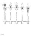
- FIG. 1 a part of a fuel filter with an upper valve 1 and a lower valve 2 is shown, which are closed by an actuator 3 , wherein the lower valve 2 in the bottom 4 of the fuel filter and thus in the region of the sump for within the filter of the Fuel deposited water is arranged, and the upper valve 1 is disposed in the cover 5 of the fuel filter on the lower valve 2 and serves as a ventilation or vent valve.
- the actuating device 3 comprises a first part 6 which closes the upper valve 1 and a second part 7 which closes the lower valve 2 and which are connected to one another via a coupling 8 .
- the upper valve is formed with a valve seat 9 and a screw thread 11 arranged underneath. Accordingly, the first part 6 of the actuator with a screw head 12 , a disposed underneath and cooperating with the valve seat 9 seal 13 , a arranged underneath and cooperating with the screw thread 11 screw bolt piece 14 and an adjoining coupling piece 15 is formed.
- the lower valve 2 has a valve seat 16 which is formed as a downwardly directed, hollow-cylindrical bulge in the bottom 4 of the fuel filter and is open at the bottom as a water drain.
- the second part 7 of the actuator 3 is formed as a valve rod 17 with a coupling piece 18 at its upper end and an O-ring-like seal 19 at its lower, engaging in the valve seat 16 end.
- valves 1 , 2 and the actuator 3 is usually, but not necessarily, vertically within a fuel filter housing, the arrangement may be depending on the type of filter cartridge used on the dirty or on the clean side of the filter cartridge.
- the coupling piece 15 of the first part 6 of the actuator 3 has four downwardly directed, circumferentially juxtaposed webs 21 arranged at their free ends, outwardly directed latching lugs 22 . They act as a latching mechanism with the coupling piece 18 of the second part 7 , which is designed as concentric with the longitudinal axis of the actuator 3 extending sleeve 23 with four formed in its side wall slots 24 , which acts upwardly by acting as a stop, circumferential annular rib 25 of the sleeve 23 are limited.
- the locking lugs 22 engage in the slots 24 , so that the first part 6 and the second part 7 are movably connected to each other, wherein the relative movement is limited by the upper edges and lower edges of the slots and in particular a release of the two parts 6 , 7 is prevented by the annular web 25 acting as a stop.
- the coupling is that the locking lugs 22 do not engage in slots 24 , but click into an end edge of the coupling piece 18 of the second part of the actuator 3 .
- the free diameter can be reduced, so that the webs 21 are elastically deformed upon insertion of the coupling piece 15 of the first part 6 of the actuator 3 to snap open after passing through the narrowed site.
- the coupling piece 15 is captively connected to the coupling piece 18.
- the first part 6 of the actuating device 3 with the seal 13 close the valve seat 9 of the upper valve 1 and the seal 19 the valve seat 16 of the lower valve 2 in each case tightly.
- the actuator is in the operating position in which the fuel filter is used to filter fuel.
- venting screw 8 is further pulled out, then the state shown in illustration "D" can occur.
- the valve rod 13 is pulled out of the valve seat 16 of the lower valve 2.
- the lower valve is actuated, ie it is opened. It can drain off water or liquid.
Landscapes
- Engineering & Computer Science (AREA)
- Chemical & Material Sciences (AREA)
- General Engineering & Computer Science (AREA)
- Mechanical Engineering (AREA)
- Combustion & Propulsion (AREA)
- Chemical Kinetics & Catalysis (AREA)
- Lift Valve (AREA)
- Filtration Of Liquid (AREA)
Applications Claiming Priority (2)
| Application Number | Priority Date | Filing Date | Title |
|---|---|---|---|
| DE102004002833A DE102004002833A1 (de) | 2004-01-20 | 2004-01-20 | Filter mit Betätigungseinrichtung zum Ablassen von abgeschiedenen Wasser |
| DE102004002833 | 2004-01-20 |
Publications (2)
| Publication Number | Publication Date |
|---|---|
| EP1557556A1 true EP1557556A1 (fr) | 2005-07-27 |
| EP1557556B1 EP1557556B1 (fr) | 2007-10-10 |
Family
ID=34625722
Family Applications (1)
| Application Number | Title | Priority Date | Filing Date |
|---|---|---|---|
| EP05100083A Expired - Lifetime EP1557556B1 (fr) | 2004-01-20 | 2005-01-10 | Filtre avec un élément d'actionnement pour vider l'eau séparée |
Country Status (2)
| Country | Link |
|---|---|
| EP (1) | EP1557556B1 (fr) |
| DE (2) | DE102004002833A1 (fr) |
Citations (8)
| Publication number | Priority date | Publication date | Assignee | Title |
|---|---|---|---|---|
| US4491120A (en) * | 1983-06-24 | 1985-01-01 | Stanadyne, Inc. | Fuel conditioner |
| US4724074A (en) * | 1985-10-07 | 1988-02-09 | Parker Hannifin Corporation | Self-venting drain assembly |
| US5606989A (en) * | 1995-06-01 | 1997-03-04 | Dana Corporation | Self-venting valve arrangement |
| US5855772A (en) * | 1996-11-01 | 1999-01-05 | Fleetguard, Inc. | Fuel filter and water separator apparatus with heater |
| US5904844A (en) * | 1985-05-14 | 1999-05-18 | Parker Intangibles Inc. | Fuel filter element |
| WO2003035217A1 (fr) * | 2001-09-19 | 2003-05-01 | Delphi Technologies, Inc. | Dispositif de filtration a ensemble de purge ameliore et ligne d'alimentation en gazole comportant un tel dispositif |
| US6565746B1 (en) * | 2002-04-30 | 2003-05-20 | Dana Corporation | One-piece self-venting drain valve |
| WO2004007942A1 (fr) * | 2002-07-11 | 2004-01-22 | Parker Hannifin (Uk) Limited | Perfectionnements apportes a des vannes electromagnetiques de vidange carburant |
-
2004
- 2004-01-20 DE DE102004002833A patent/DE102004002833A1/de not_active Withdrawn
-
2005
- 2005-01-10 DE DE502005001640T patent/DE502005001640D1/de not_active Expired - Lifetime
- 2005-01-10 EP EP05100083A patent/EP1557556B1/fr not_active Expired - Lifetime
Patent Citations (8)
| Publication number | Priority date | Publication date | Assignee | Title |
|---|---|---|---|---|
| US4491120A (en) * | 1983-06-24 | 1985-01-01 | Stanadyne, Inc. | Fuel conditioner |
| US5904844A (en) * | 1985-05-14 | 1999-05-18 | Parker Intangibles Inc. | Fuel filter element |
| US4724074A (en) * | 1985-10-07 | 1988-02-09 | Parker Hannifin Corporation | Self-venting drain assembly |
| US5606989A (en) * | 1995-06-01 | 1997-03-04 | Dana Corporation | Self-venting valve arrangement |
| US5855772A (en) * | 1996-11-01 | 1999-01-05 | Fleetguard, Inc. | Fuel filter and water separator apparatus with heater |
| WO2003035217A1 (fr) * | 2001-09-19 | 2003-05-01 | Delphi Technologies, Inc. | Dispositif de filtration a ensemble de purge ameliore et ligne d'alimentation en gazole comportant un tel dispositif |
| US6565746B1 (en) * | 2002-04-30 | 2003-05-20 | Dana Corporation | One-piece self-venting drain valve |
| WO2004007942A1 (fr) * | 2002-07-11 | 2004-01-22 | Parker Hannifin (Uk) Limited | Perfectionnements apportes a des vannes electromagnetiques de vidange carburant |
Also Published As
| Publication number | Publication date |
|---|---|
| EP1557556B1 (fr) | 2007-10-10 |
| DE102004002833A1 (de) | 2005-08-04 |
| DE502005001640D1 (de) | 2007-11-22 |
Similar Documents
| Publication | Publication Date | Title |
|---|---|---|
| EP0314915B1 (fr) | Filtre permettant la purification des huiles de graissage | |
| DE112008001571B4 (de) | Fluidfilter und Verfahren zur Wartung eines Fluidfilters | |
| EP0381069B1 (fr) | Manchon d'accouplement pour lignes d'interconnexion hydraulique | |
| EP0968382B1 (fr) | Soupape a double siege nettoyable | |
| EP0402559B1 (fr) | Vanne de distribution | |
| EP2054132B1 (fr) | Ensemble filtre à huile | |
| EP1172549A2 (fr) | Filtre à carburant | |
| EP2530365B2 (fr) | Garniture de soupape pour une armature sanitaire | |
| EP2741837B1 (fr) | Filtre pour liquide comportant une vanne d'évacuation | |
| EP2043752B1 (fr) | Ensemble filtre à huile | |
| DE102012210834A1 (de) | Flüssigkeitsfilter mit einem Filterumgehungsventil und einem zentralen Ablasskanal und Filtereinsatz für ein Flüssigkeitsfilter | |
| WO2016162083A1 (fr) | Dispositif de filtration | |
| EP2203667A1 (fr) | Soupape a double siege avec possibilite de nettoyage de siege et procede de nettoyage de cette soupape | |
| DE102018221257A1 (de) | Vormontage-Baugruppe mit einem Filterelement | |
| EP3545801A1 (fr) | Machine à boisson avec système de drainage pour eau résiduelle | |
| WO2018115252A1 (fr) | Commande séquentielle de fluide au moyen d'un dispositif d'étanchéité | |
| EP1557556B1 (fr) | Filtre avec un élément d'actionnement pour vider l'eau séparée | |
| EP0637711B1 (fr) | Vanne pour fluides | |
| EP0195389B2 (fr) | Déconnecteur de tuyaux | |
| DE60213277T2 (de) | Filter und filterreinigungsvorrichtung sowie verwandte verfahren | |
| DE102018221256A1 (de) | Filterelement für eine Filtereinrichtung | |
| DE102018221259A1 (de) | Baugruppe für eine Filtereinrichtung | |
| EP0983442B1 (fr) | Dispositif d'actionnement a commande manuelle d'urgence | |
| DE102008024044B4 (de) | Ventilanordnung | |
| DE8206970U1 (de) | Vorrichtung zum absperren und belueften einer rohrleitung |
Legal Events
| Date | Code | Title | Description |
|---|---|---|---|
| PUAI | Public reference made under article 153(3) epc to a published international application that has entered the european phase |
Free format text: ORIGINAL CODE: 0009012 |
|
| AK | Designated contracting states |
Kind code of ref document: A1 Designated state(s): AT BE BG CH CY CZ DE DK EE ES FI FR GB GR HU IE IS IT LI LT LU MC NL PL PT RO SE SI SK TR |
|
| AX | Request for extension of the european patent |
Extension state: AL BA HR LV MK YU |
|
| 17P | Request for examination filed |
Effective date: 20060127 |
|
| AKX | Designation fees paid |
Designated state(s): DE FR IT |
|
| 17Q | First examination report despatched |
Effective date: 20060821 |
|
| GRAP | Despatch of communication of intention to grant a patent |
Free format text: ORIGINAL CODE: EPIDOSNIGR1 |
|
| GRAS | Grant fee paid |
Free format text: ORIGINAL CODE: EPIDOSNIGR3 |
|
| GRAA | (expected) grant |
Free format text: ORIGINAL CODE: 0009210 |
|
| AK | Designated contracting states |
Kind code of ref document: B1 Designated state(s): DE FR IT |
|
| REF | Corresponds to: |
Ref document number: 502005001640 Country of ref document: DE Date of ref document: 20071122 Kind code of ref document: P |
|
| ET | Fr: translation filed | ||
| PLBE | No opposition filed within time limit |
Free format text: ORIGINAL CODE: 0009261 |
|
| STAA | Information on the status of an ep patent application or granted ep patent |
Free format text: STATUS: NO OPPOSITION FILED WITHIN TIME LIMIT |
|
| 26N | No opposition filed |
Effective date: 20080711 |
|
| REG | Reference to a national code |
Ref country code: FR Ref legal event code: PLFP Year of fee payment: 12 |
|
| REG | Reference to a national code |
Ref country code: FR Ref legal event code: PLFP Year of fee payment: 13 |
|
| REG | Reference to a national code |
Ref country code: FR Ref legal event code: PLFP Year of fee payment: 14 |
|
| PGFP | Annual fee paid to national office [announced via postgrant information from national office to epo] |
Ref country code: DE Payment date: 20240322 Year of fee payment: 20 |
|
| PGFP | Annual fee paid to national office [announced via postgrant information from national office to epo] |
Ref country code: IT Payment date: 20240131 Year of fee payment: 20 Ref country code: FR Payment date: 20240123 Year of fee payment: 20 |
|
| REG | Reference to a national code |
Ref country code: DE Ref legal event code: R071 Ref document number: 502005001640 Country of ref document: DE |