EP1557561B1 - Alimentation d'appoint pour générateur et procédé de commande associé - Google Patents
Alimentation d'appoint pour générateur et procédé de commande associé Download PDFInfo
- Publication number
- EP1557561B1 EP1557561B1 EP03738607.5A EP03738607A EP1557561B1 EP 1557561 B1 EP1557561 B1 EP 1557561B1 EP 03738607 A EP03738607 A EP 03738607A EP 1557561 B1 EP1557561 B1 EP 1557561B1
- Authority
- EP
- European Patent Office
- Prior art keywords
- voltage
- circuit
- moment
- converter
- boosting
- Prior art date
- Legal status (The legal status is an assumption and is not a legal conclusion. Google has not performed a legal analysis and makes no representation as to the accuracy of the status listed.)
- Expired - Lifetime
Links
Images



Classifications
-
- F—MECHANICAL ENGINEERING; LIGHTING; HEATING; WEAPONS; BLASTING
- F02—COMBUSTION ENGINES; HOT-GAS OR COMBUSTION-PRODUCT ENGINE PLANTS
- F02P—IGNITION, OTHER THAN COMPRESSION IGNITION, FOR INTERNAL-COMBUSTION ENGINES; TESTING OF IGNITION TIMING IN COMPRESSION-IGNITION ENGINES
- F02P15/00—Electric spark ignition having characteristics not provided for in, or of interest apart from, groups F02P1/00 - F02P13/00 and combined with layout of ignition circuits
- F02P15/12—Electric spark ignition having characteristics not provided for in, or of interest apart from, groups F02P1/00 - F02P13/00 and combined with layout of ignition circuits having means for strengthening spark during starting
-
- H—ELECTRICITY
- H02—GENERATION; CONVERSION OR DISTRIBUTION OF ELECTRIC POWER
- H02M—APPARATUS FOR CONVERSION BETWEEN AC AND AC, BETWEEN AC AND DC, OR BETWEEN DC AND DC, AND FOR USE WITH MAINS OR SIMILAR POWER SUPPLY SYSTEMS; CONVERSION OF DC OR AC INPUT POWER INTO SURGE OUTPUT POWER; CONTROL OR REGULATION THEREOF
- H02M3/00—Conversion of DC power input into DC power output
- H02M3/02—Conversion of DC power input into DC power output without intermediate conversion into AC
- H02M3/04—Conversion of DC power input into DC power output without intermediate conversion into AC by static converters
- H02M3/10—Conversion of DC power input into DC power output without intermediate conversion into AC by static converters using discharge tubes with control electrode or semiconductor devices with control electrode
- H02M3/145—Conversion of DC power input into DC power output without intermediate conversion into AC by static converters using discharge tubes with control electrode or semiconductor devices with control electrode using devices of a triode or transistor type requiring continuous application of a control signal
- H02M3/155—Conversion of DC power input into DC power output without intermediate conversion into AC by static converters using discharge tubes with control electrode or semiconductor devices with control electrode using devices of a triode or transistor type requiring continuous application of a control signal using semiconductor devices only
- H02M3/156—Conversion of DC power input into DC power output without intermediate conversion into AC by static converters using discharge tubes with control electrode or semiconductor devices with control electrode using devices of a triode or transistor type requiring continuous application of a control signal using semiconductor devices only with automatic control of output voltage or current, e.g. switching regulators
-
- B—PERFORMING OPERATIONS; TRANSPORTING
- B60—VEHICLES IN GENERAL
- B60R—VEHICLES, VEHICLE FITTINGS, OR VEHICLE PARTS, NOT OTHERWISE PROVIDED FOR
- B60R16/00—Electric or fluid circuits specially adapted for vehicles and not otherwise provided for; Arrangement of elements of electric or fluid circuits specially adapted for vehicles and not otherwise provided for
- B60R16/02—Electric or fluid circuits specially adapted for vehicles and not otherwise provided for; Arrangement of elements of electric or fluid circuits specially adapted for vehicles and not otherwise provided for electric constitutive elements
- B60R16/03—Electric or fluid circuits specially adapted for vehicles and not otherwise provided for; Arrangement of elements of electric or fluid circuits specially adapted for vehicles and not otherwise provided for electric constitutive elements for supply of electrical power to vehicle subsystems or for
-
- F—MECHANICAL ENGINEERING; LIGHTING; HEATING; WEAPONS; BLASTING
- F02—COMBUSTION ENGINES; HOT-GAS OR COMBUSTION-PRODUCT ENGINE PLANTS
- F02N—STARTING OF COMBUSTION ENGINES; STARTING AIDS FOR SUCH ENGINES, NOT OTHERWISE PROVIDED FOR
- F02N3/00—Other muscle-operated starting apparatus
- F02N3/04—Other muscle-operated starting apparatus having foot-actuated levers
-
- F—MECHANICAL ENGINEERING; LIGHTING; HEATING; WEAPONS; BLASTING
- F02—COMBUSTION ENGINES; HOT-GAS OR COMBUSTION-PRODUCT ENGINE PLANTS
- F02P—IGNITION, OTHER THAN COMPRESSION IGNITION, FOR INTERNAL-COMBUSTION ENGINES; TESTING OF IGNITION TIMING IN COMPRESSION-IGNITION ENGINES
- F02P3/00—Other installations
- F02P3/06—Other installations having capacitive energy storage
- F02P3/08—Layout of circuits
- F02P3/0876—Layout of circuits the storage capacitor being charged by means of an energy converter (DC-DC converter) or of an intermediate storage inductance
- F02P3/0884—Closing the discharge circuit of the storage capacitor with semiconductor devices
- F02P3/0892—Closing the discharge circuit of the storage capacitor with semiconductor devices using digital techniques
-
- H—ELECTRICITY
- H02—GENERATION; CONVERSION OR DISTRIBUTION OF ELECTRIC POWER
- H02M—APPARATUS FOR CONVERSION BETWEEN AC AND AC, BETWEEN AC AND DC, OR BETWEEN DC AND DC, AND FOR USE WITH MAINS OR SIMILAR POWER SUPPLY SYSTEMS; CONVERSION OF DC OR AC INPUT POWER INTO SURGE OUTPUT POWER; CONTROL OR REGULATION THEREOF
- H02M1/00—Details of apparatus for conversion
- H02M1/0003—Details of control, feedback or regulation circuits
- H02M1/0016—Control circuits providing compensation of output voltage deviations using feedforward of disturbance parameters
- H02M1/0022—Control circuits providing compensation of output voltage deviations using feedforward of disturbance parameters the disturbance parameters being input voltage fluctuations
Definitions
- the present invention relates to a voltage booster for engine generator and control method thereof.
- a motor bicycle uses as an engine start ignition circuit the CDI (capacitor discharge igniter) method and the full transistor igniter method.
- the CDI can operate regardless of presence/absence of a battery and can perform engine start by a so-called kick method.
- the CDI has a problem that it is inferior to the full transistor igniter method when igniting a dilute air-fuel mixture.
- the full transistor igniter method is appropriate for energy saving such as optimal ignition control of engine but requires a battery and cannot start an engine by the kick method.
- the full transistor igniter circuit includes a generator 1, a voltage adjusting unit 2, a battery 8, a lamp 3, an engine control unit (ECU) 4, an igniter 5, an injector 6, a fuel pump 7, and other DC load 9 connected in parallel.
- ECU engine control unit
- an igniter 5 an injector 6, a fuel pump 7, and other DC load 9 connected in parallel.
- a main switch 11 is such as a starter button is closed, voltage from the battery 8 is supplied to the entire circuit to operate the ECU 4 and relays 10, 40 are closed to start the engine.
- An engine start ignition circuit according to the precharacterizing part of claim 1 is known from EP 1 235 342 A . Further relevant State of the Art is disclosed in US 5 404 859 A and JP 01 224474 A .
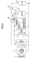
- Fig. 2 shows the entire configuration of the voltage booster for engine generator according to the present invention.
- the voltage booster for engine generator of Fig. 2 is characterized in that the DC/DC converter 20 is connected as an active booster circuit between the voltage adjustment unit (REG) 2 and the electronic device such as the ECU 4 connected to the REG 2 to receive voltage.
- the battery 8 shown in the figure is in the discharge state below a predetermined start voltage upon start by the kick method as an object of the present invention and it is assumed that the generator 1 is driven by the so-called kick method. After the engine reaches a stationary rotation, the battery 8 is charged and afterwards, the engine can be started by the battery 8.
- a diode 39 is inserted between the DC/DC converter 20 and the battery 8, so as to prevent flow in of current to the side of the battery 8 having a large current capacity upon boosting of the DC/DC converter 20.
- Fig. 3 shows detailed configuration of this DC/DC converter 20.
- the DC/DC converter basically consists of a diode 23, a coil 24, and a diode 25 which are connected in series and a capacitor 26, a transistor 27, and a capacitor 30 which are connected between the series connection and the ground line.
- a bypass circuit 21 consisting of a diode 22 connected in parallel between the diodes 23 and 25 is provided. Furthermore, a feedback circuit 32 including a Zener diode 30 is arranged. Furthermore, the output of the feedback circuit 32 is connected to an oscillation circuit 31. This oscillation circuit 31 is configured so as to supply a drive signal to the base of the transistor 27 via a resistor 28.
- the control voltage V1 of the REG 2 (output fluctuating depending on the rpm of the generator) is compared to the control voltage V2 of the DC/DC converter 20 (a reference voltage such as 12V at which the engine performs stationary rotation and the electronic devices operate normally). That is, when the control voltage V1 of the REG 2 by a low rpm at rotation start by turning on the main switch 11 and kicking the ACG 1 is lower than the control voltage V2 of the DC/DC converter 20 (V1 ⁇ V2), the voltage value passing through the bypass circuit 21 and subtracted by the voltage drop by the diode 22 (V1 - voltage drop of diode) is applied.
- the voltage value detected is input to the feedback circuit 32 and the relationship of V1 ⁇ V2 is recognized.
- the feedback circuit outputs a feedback signal corresponding to the difference between the V1 and V2 to the oscillation circuit 31 so as to drive the oscillation circuit 31.
- the oscillation circuit 31 sends a corresponding drive signal to the base of the transistor 27 via the resistor 28.
- the transistor 27 is conducted/controlled and the DC/DC converter 20 operates to boost the voltage from the current V1 to the control voltage V2 which is a reference voltage.
- the ECU 4 When the reference voltage V2 boosted by the DC/DC converter 20 is output, the ECU 4 operates and the engine starts operation. With this engine start, the ACG 1 is driven by the engine to increase the rpm. When the ACG 1 reaches the stationary rotation, the voltage applied to the Zener diode 30 via the bypass circuit 21 is increased step by step to a value equal to or above V2 when subtracted by the voltage drop of the diode 22. At this moment, a voltage equal to or above 2V which is the preset output of the DC/DC convert 20 is detected by the feedback circuit 32 (V1 > V2) .
- the feedback circuit 32 transmits a feedback signal so as to stop drive output of the oscillation circuit 31 to the transistor 27.
- the boosting operation of the DC/DC converter 20 stops.
- the control voltage V1 of the REG 2 which has become equal to or above the control voltage V2 of the DC/DC converter 20 is bypassed by the diode 22 of the bypass circuit 21 and supplied dto the electronic circuits such as the ECU 4.
- the relays 10, 40 are closed and a reference voltage is applied to the DC load 9, thereby starting charge of the battery 8.
- the engine performs stationary rotation and the ACG 1 generates above the nominal output.
- the output voltage of the stationary operation is obtained and supplied via the bypass circuit 21 to the ECU 4 and other electronic devices.
- the bypass circuit 21 is composed of a diode but it can also be replaced by a resistor.
- the oscillation circuit 31 may be configured to oscillate stationary drive frequency such as 50 KHz and cut off the DC/DC converter circuit by the relay using a signal of the feedback circuit 32 instead of using control of PWM and PFM.
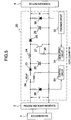
- the bypass circuit 21 is composed of a relay 34 and a control circuit 34 is provided to operate the relay 34.
- This control circuit 33 includes a Zener diode 38 for monitoring voltage V1 arranged at the input side of the DC/DC converter 20.
- this control circuit 33 may be replaced by a timer circuit controlling ON/OFF of the relay 34 after a sufficient time when the V1 becomes greater than V2 after the start by the kick method, or may be replaced by a switching element such as a transistor. Moreover, it is possible to turn ON/OFF when the value of V1 reaches the stationary rotation value regardless of the value of V2.
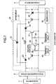
- a relay 34 is provided at the input side of the diode 23 instead of the bypass circuit 21, so as to be operated by the control circuit 33 similar to the one in Fig. 4 .
- the engine is normally started by the kick when the relay 34 is closed.
- the control circuit 33 operates to open the relay 34, so that the DC/DC converter 20 itself enters a stop state.
- V1 equal to or greater than V2 is supplied to the electronic devices such as ECU 5 connected in parallel to the REG 2 and the operation is maintained.
- the control circuit 33 monitors the control voltage V2 of the DC/DC converter, or it may be replaced by a timer operating after a lapse of a predetermined period of time.
- the relay may be replaced by the switching element such as a transistor.
- the engine performs the stationary operation and the stationary voltage from the REG 2 obtained by the stationary operation of the engine closes the relay 10, so that the stationary voltage is applied to all the circuit components shown in Fig. 2 .
- the oscillation circuit 31 boosts the control voltage V1 from the REG 2 to a predetermined voltage V2 by the feedback signal from the feedback circuit 32. Furthermore, an oscillation circuit 35 consisting of a resistor 36 and a transistor 37 is provided for terminating the operation of the transistor 27. This oscillation stop circuit 35 is controlled by a control circuit 33 having a Zener diode 38 for detecting the voltage V1 of the input side of the DC/DC converter 20.
- the control circuit 33 terminates the operation of the transistor 27 under the condition of V1 ⁇ V2 in the same way as the embodiment of Fig. 3 and substantially terminates the operation of the DC/DC converter 20.
- the control circuit 33 may directly monitor the voltage V1 or timer operation can be used to terminate the oscillation stop circuit 35. In this configuration also, it is possible to employ a relay operating upon a voltage of stationary rotation regardless of the value of V2.
- the oscillation circuit 31 performs feedback control by the feedback circuit 32 and a bypass circuit 21 consisting of a diode 22 is provided in parallel.
- the feedback circuit 32 monitors the control voltage V1 of the REG 2 and upon detection of V1 > V2, the control circuit 33 operates the oscillation stop circuit 35.
- the engine after stop of bossing operation of the DC/DC converter 20, the engine performs stationary operation and the stationary voltage from the REG 2 operates the oscillation stop circuit 35, so that the stationary voltage is applied to all the circuit components shown in Fig. 2 .
- this configuration also, it is possible to use an oscillation stop circuit operating upon a voltage of the stationary rotation regardless of the value of V2.
- the voltage booster for engine generator and control method thereof enables the engine ignition circuit of the full transistor igniter method to start the engine by the so-called kick method even when the battery is in a discharge state.
Landscapes
- Engineering & Computer Science (AREA)
- Power Engineering (AREA)
- Chemical & Material Sciences (AREA)
- Combustion & Propulsion (AREA)
- Mechanical Engineering (AREA)
- General Engineering & Computer Science (AREA)
- Ignition Installations For Internal Combustion Engines (AREA)
- Dc-Dc Converters (AREA)
- Electrical Control Of Ignition Timing (AREA)
- Control Of Eletrric Generators (AREA)
Claims (9)
- Circuit d'allumage de démarrage de moteur incluant un amplificateur de tension pour un générateur de moteur lequel correspond à un appareil d'allumage de moteur faisant appel au procédé d'allumage complètement transistorisé, dans lequel le circuit d'allumage de démarrage de moteur comporte :un générateur (1) qui peut être commandé par le procédé de démarrage au pied ;un dispositif de réglage de tension (2) connecté au générateur (1) pour régler une tension de puissance fournie par le générateur (1) ;un dispositif électronique (4) connecté au dispositif de réglage de tension (2) pour commander une commande d'allumage/fonctionnement du moteur par la tension fournie par le dispositif de réglage de tension (2) ; etun circuit d'amplification active (20) connecté entre le dispositif de réglage de tension (2) et le dispositif électronique (4), pour amplifier la tension de sortie du dispositif de réglage de tension (2) jusqu'à une tension nominale prédéterminée du dispositif électronique (4) lors du démarrage de moteur par un démarrage au pied du générateur (1) lorsque l'alimentation électrique est inférieure au fonctionnement stationnaire de moteur prédéterminé, et pour interrompre l'opération d'amplification lorsque la tension de sortie provenant du dispositif de réglage de tension (2) a atteint la tension nominale prédéterminée du fonctionnement stationnaire de moteur, dans lequel ledit circuit d'amplification active (20) inclut en outre un condensateur pour charger une force électromotrice au moins par ledit démarrage au pied, dans lequelledit circuit d'amplification active (20) est un convertisseur continu - continu présentant un circuit de rétroaction (32) destiné à mettre en oeuvre une rétroaction de sorte que la tension du côté de sortie devient la tension nominale prédéterminée, dans lequelledit condensateur est inséré entre ledit circuit de rétroaction et ledit côté de sortie, caractérisé en ce que :ledit circuit d'amplification active (20) comporte en outre un circuit de dérivation (21) permettant une dérivation, du côté de générateur au côté de charge du circuit d'amplification active (20) ; etdans lequel le circuit de rétroaction (32) interrompt l'opération d'amplification du convertisseur continu - continu (20) lorsqu'une tension V1 du côté de générateur dérivé vers le côté de charge du convertisseur continu - continu (20), qui est réduite par une chute de tension du circuit de dérivation, est supérieure à une tension nominale prédéterminée V2 (V1 - chute de tension de circuit de dérivation > V2).
- Circuit d'allumage de démarrage de moteur selon la revendication 1, dans lequel :le circuit de dérivation (21) dispose d'un relais (34) qui est normalement ouvert pour la dérivation du côté de générateur au côté de charge du circuit d'amplification active (20) ; etledit circuit d'amplification active (20) comporte en outre un circuit de commande (33) pour détecter la tension du côté de générateur du circuit d'amplification active (20) et fermer le relais (34) qui est normalement ouvert ; etdans lequel le circuit de commande (33) est configuré de manière à fermer le relais (34) de manière à interrompre l'opération d'amplification du convertisseur continu - continu (20), au moment où la tension V1 du côté de générateur est devenue une tension prédéterminée, à partir du dispositif de réglage de tension (2), au cours du fonctionnement stationnaire, de sorte que le circuit de commande (33) se ferme.
- Circuit d'allumage de démarrage de moteur selon la revendication 2, dans lequel le moment de la tension prédéterminée correspond à un moment où la tension nominale prédéterminée V2 est dépassée (V1 > V2), et dans lequel le relais (34) est fermé à ce moment, et dans lequel le circuit de rétroaction interrompt l'opération d'amplification du convertisseur continu - continu I (20) lorsque la tension V1 du côté de générateur dérivé par le côté de charge du convertisseur continu - continu dépasse la tension nominale prédéterminée (V1 > V2).
- Circuit d'allumage de démarrage de moteur selon la revendication 1, dans lequel le circuit d'amplification active inclut :un relais (34) qui est fourni au niveau du côté de générateur et qui est normalement fermé ; etun circuit de commande (33) destiné à faire fonctionner le relais (34) selon la tension V1 au niveau du côté de générateur du circuit d'amplification active (20) ; etdans lequel le circuit de commande (33) ouvre le relais (34) au moment où la tension V1 du côté de générateur est devenue une tension prédéterminée, à partir du dispositif de réglage de tension (2), au cours du fonctionnement stationnaire, afin d'interrompre l'opération d'amplification du convertisseur continu - continu (20).
- Circuit d'allumage de démarrage de moteur selon la revendication 4, dans lequel le moment où la tension prédéterminée est obtenue correspond au moment où la tension est devenue égale ou supérieure à la tension nominale V2 (V1 ≥ V2), et dans lequel, à ce moment, le relais (34) est ouvert.
- Circuit d'allumage de démarrage de moteur selon la revendication 5, dans lequel le circuit de commande est configuré de manière à interrompre un circuit d'arrêt d'oscillation (31) et l'opération d'amplification du convertisseur continu - continu (20) au moment où la tension V1 du côté de générateur est devenue une tension prédéterminée, à partir du dispositif de réglage de tension (2), au cours du fonctionnement stationnaire.
- Circuit d'allumage de démarrage de moteur selon la revendication 6, dans lequel le moment où la tension prédéterminée est obtenue correspond au moment où la tension est égale ou supérieure à la tension nominale (V1 ≥ V2), et dans lequel, à ce moment, le fonctionnement du convertisseur continu - continu (20) est interrompu.
- Circuit d'allumage de démarrage de moteur selon la revendication 1, dans lequel, lorsque le convertisseur continu - continu présente une tension V2 (V1 ≥ V2), à ce moment, le relais correspond à un circuit de rétroaction destiné à mettre en oeuvre une rétroaction de sorte que la tension du côté de sortie devient la tension nominale prédéterminée V2 ; et
dans lequel le circuit d'allumage de démarrage de moteur comporte en outre :un circuit de commande (33) pour mettre fin au fonctionnement du circuit d'amplification active par la sortie du circuit de rétroaction (32) ; etau moment où la tension V1 du côté d'entrée dérivé par le côté de sortie est devenue une tension prédéterminée, à partir du dispositif de réglage de tension (2), au cours du fonctionnement stationnaire, le circuit de rétroaction interrompt l'opération d'amplification du convertisseur continu - continu (20) . - Circuit d'allumage de démarrage de moteur selon la revendication 8, dans lequel le moment prédéterminé correspond au moment où la tension a dépassé la tension nominale V2, et dans lequel, à ce moment, l'opération d'amplification du convertisseur continu - continu (20) est interrompue en commandant le circuit de commande.
Applications Claiming Priority (3)
| Application Number | Priority Date | Filing Date | Title |
|---|---|---|---|
| JP2002194897 | 2002-07-03 | ||
| JP2002194897A JP4209640B2 (ja) | 2002-07-03 | 2002-07-03 | エンジン発電機用昇圧電源 |
| PCT/JP2003/008358 WO2004005705A1 (fr) | 2002-07-03 | 2003-07-01 | Alimentation d'appoint pour generateur et procede de commande associe |
Publications (3)
| Publication Number | Publication Date |
|---|---|
| EP1557561A1 EP1557561A1 (fr) | 2005-07-27 |
| EP1557561A4 EP1557561A4 (fr) | 2009-04-08 |
| EP1557561B1 true EP1557561B1 (fr) | 2017-12-06 |
Family
ID=30112317
Family Applications (1)
| Application Number | Title | Priority Date | Filing Date |
|---|---|---|---|
| EP03738607.5A Expired - Lifetime EP1557561B1 (fr) | 2002-07-03 | 2003-07-01 | Alimentation d'appoint pour générateur et procédé de commande associé |
Country Status (5)
| Country | Link |
|---|---|
| EP (1) | EP1557561B1 (fr) |
| JP (1) | JP4209640B2 (fr) |
| CN (1) | CN1316725C (fr) |
| BR (1) | BR0312279A (fr) |
| WO (1) | WO2004005705A1 (fr) |
Families Citing this family (13)
| Publication number | Priority date | Publication date | Assignee | Title |
|---|---|---|---|---|
| EP1876694A1 (fr) * | 2006-07-03 | 2008-01-09 | Siemens Aktiengesellschaft | Circuit élévateur de tension |
| FR2904157B1 (fr) * | 2006-07-24 | 2008-12-05 | Valeo Sys Controle Moteur Sas | Circuit electrique d'alimentation d'un module de commande comportant deux modes d'alimentation |
| JP5024963B2 (ja) | 2008-07-23 | 2012-09-12 | オムロンオートモーティブエレクトロニクス株式会社 | エンジン始動装置 |
| FR2942555B1 (fr) * | 2009-02-20 | 2011-02-18 | Continental Automotive France | Calculateur de vehicule automobile comportant un dispositif elevateur de tension et procede de commande |
| US7938092B2 (en) * | 2009-06-19 | 2011-05-10 | Tai-Her Yang | Combustion and emergency starting control system with auxiliary power |
| US8490593B2 (en) * | 2009-06-19 | 2013-07-23 | Tai-Her Yang | Split-type auxiliary power combustion and emergency starting system |
| JP5692151B2 (ja) | 2012-04-25 | 2015-04-01 | 株式会社デンソー | 車載電子制御装置 |
| DE102013218227A1 (de) | 2012-09-12 | 2014-05-28 | Robert Bosch Gmbh | Zündsystem für eine Verbrennungskraftmaschine |
| EP2895734B1 (fr) | 2012-09-12 | 2019-03-27 | Robert Bosch GmbH | Système d'allumage conçu pour un moteur à combustion interne |
| CN102979656A (zh) * | 2012-12-10 | 2013-03-20 | 南京航空航天大学 | 一种自适应高能点火系统 |
| DE102016207132B4 (de) * | 2016-04-27 | 2020-06-04 | Continental Automotive Gmbh | Verfahren und Schaltungsvorrichtung zum Stabilisieren einer Bordnetzspannung |
| JP2019154129A (ja) * | 2018-03-02 | 2019-09-12 | パナソニックIpマネジメント株式会社 | 移動体用電源装置および当該移動体用電源装置を用いた移動体 |
| US11319915B2 (en) | 2020-06-11 | 2022-05-03 | Kohler Co. | Engine system, and method of starting the engine |
Family Cites Families (12)
| Publication number | Priority date | Publication date | Assignee | Title |
|---|---|---|---|---|
| JPS51132339A (en) * | 1974-12-30 | 1976-11-17 | Yoshio Fujino | Auxiliary power source device for starting of firework ignition type e ngine |
| JPS58143165A (ja) * | 1982-02-19 | 1983-08-25 | Automob Antipollut & Saf Res Center | 内燃機関の点火装置 |
| JPH0322551Y2 (fr) * | 1984-09-07 | 1991-05-16 | ||
| JPH01224474A (ja) * | 1988-03-01 | 1989-09-07 | Mitsubishi Electric Corp | 機関制御装置 |
| JPH0750985B2 (ja) * | 1989-06-29 | 1995-05-31 | 阪神エレクトリック株式会社 | Dc―dcコンバータ |
| JPH04132877A (ja) * | 1990-09-21 | 1992-05-07 | Yamaha Motor Co Ltd | 自動二輪車の始動装置 |
| JP2749746B2 (ja) * | 1992-11-18 | 1998-05-13 | 三菱電機株式会社 | 内燃機関点火装置 |
| JPH06229312A (ja) * | 1993-02-01 | 1994-08-16 | Toyota Motor Corp | 内燃機関の制御装置 |
| JP3722567B2 (ja) * | 1996-09-19 | 2005-11-30 | 株式会社ミツバ | 点火制御装置 |
| CN1245867A (zh) * | 1998-08-25 | 2000-03-01 | 郭建国 | 一种产生汽车高压点火的方法及其装置 |
| JP3889212B2 (ja) * | 2000-09-25 | 2007-03-07 | 本田技研工業株式会社 | 発電機の発電電圧昇圧方法 |
| JP2002256962A (ja) * | 2001-02-26 | 2002-09-11 | Mikuni Corp | 内燃機関用電源装置 |
-
2002
- 2002-07-03 JP JP2002194897A patent/JP4209640B2/ja not_active Expired - Fee Related
-
2003
- 2003-07-01 EP EP03738607.5A patent/EP1557561B1/fr not_active Expired - Lifetime
- 2003-07-01 WO PCT/JP2003/008358 patent/WO2004005705A1/fr not_active Ceased
- 2003-07-01 CN CNB038191652A patent/CN1316725C/zh not_active Expired - Fee Related
- 2003-07-01 BR BR0312279-4A patent/BR0312279A/pt not_active Application Discontinuation
Non-Patent Citations (1)
| Title |
|---|
| None * |
Also Published As
| Publication number | Publication date |
|---|---|
| EP1557561A4 (fr) | 2009-04-08 |
| JP2004036494A (ja) | 2004-02-05 |
| EP1557561A1 (fr) | 2005-07-27 |
| CN1316725C (zh) | 2007-05-16 |
| JP4209640B2 (ja) | 2009-01-14 |
| CN1675464A (zh) | 2005-09-28 |
| WO2004005705A1 (fr) | 2004-01-15 |
| BR0312279A (pt) | 2005-04-26 |
Similar Documents
| Publication | Publication Date | Title |
|---|---|---|
| JP3625789B2 (ja) | 車両の電源装置 | |
| EP0751602B1 (fr) | Système de régulation pour un générateur de véhicule | |
| EP1557561A1 (fr) | Alimentation d'appoint pour generateur et procede de commande associe | |
| WO1999015402A2 (fr) | Systemes de demarrage et controleurs pour moteurs d'avion a turbine et procedes de demarrage de moteurs d'avion a turbine | |
| US7639519B2 (en) | Switching booster power circuit | |
| CN113395060B (zh) | 用于驱动开关装置的设备及其使用方法 | |
| US6215284B1 (en) | Control device of A.C. generator for vehicle | |
| CA2872244A1 (fr) | Circuit d'alimentation electrique destine a un vehicule | |
| US9014942B2 (en) | Idling stop device and idling stop control method | |
| JP3502250B2 (ja) | スタータ保護装置 | |
| US6741067B2 (en) | Power generation controller and method for a vehicle | |
| JP7461253B2 (ja) | 昇圧型スイッチングレギュレータ | |
| US6707278B2 (en) | Transition voltage start regulator | |
| CN119654783A (zh) | 用于对中间电路电容器的放电进行控制的设备和方法 | |
| WO1997022176A1 (fr) | Systeme de lancement pour generateur a entrainement direct | |
| KR100215659B1 (ko) | 차량의 에어콘 구동 방법 및 장치 | |
| US20040243297A1 (en) | Circuit layout and procedure to control at least one electrical component of a motor vehicle | |
| KR20200122807A (ko) | 차량 발전기의 다기능 레귤레이터 | |
| JP2006148988A (ja) | スイッチング電源回路 | |
| JP3506035B2 (ja) | エンジン始動装置 | |
| KR100999455B1 (ko) | 알터네이터 제어회로 | |
| JP2649301B2 (ja) | 自動車用発電機の発電制御装置 | |
| JPH1026030A (ja) | 電気負荷の通電制御装置 | |
| JP2005333779A (ja) | 内燃機関用電装品負荷駆動装置及び内燃機関用点火装置 | |
| JP3309650B2 (ja) | 誘導負荷駆動制御装置 |
Legal Events
| Date | Code | Title | Description |
|---|---|---|---|
| PUAI | Public reference made under article 153(3) epc to a published international application that has entered the european phase |
Free format text: ORIGINAL CODE: 0009012 |
|
| 17P | Request for examination filed |
Effective date: 20041220 |
|
| AK | Designated contracting states |
Kind code of ref document: A1 Designated state(s): AT BE BG CH CY CZ DE DK EE ES FI FR GB GR HU IE IT LI LU MC NL PT RO SE SI SK TR |
|
| A4 | Supplementary search report drawn up and despatched |
Effective date: 20090305 |
|
| 17Q | First examination report despatched |
Effective date: 20100311 |
|
| REG | Reference to a national code |
Ref country code: DE Ref legal event code: R079 Ref document number: 60350823 Country of ref document: DE Free format text: PREVIOUS MAIN CLASS: F02P0003080000 Ipc: F02P0015120000 |
|
| GRAP | Despatch of communication of intention to grant a patent |
Free format text: ORIGINAL CODE: EPIDOSNIGR1 |
|
| RIC1 | Information provided on ipc code assigned before grant |
Ipc: F02P 3/08 20060101ALN20170613BHEP Ipc: F02P 15/12 20060101AFI20170613BHEP Ipc: F02N 3/04 20060101ALN20170613BHEP |
|
| RIC1 | Information provided on ipc code assigned before grant |
Ipc: F02P 15/12 20060101AFI20170623BHEP Ipc: F02P 3/08 20060101ALN20170623BHEP Ipc: F02N 3/04 20060101ALN20170623BHEP |
|
| INTG | Intention to grant announced |
Effective date: 20170714 |
|
| RIN1 | Information on inventor provided before grant (corrected) |
Inventor name: NIIZEKI, SEIJI Inventor name: TAKASHIMA, TOYOTAKA |
|
| GRAS | Grant fee paid |
Free format text: ORIGINAL CODE: EPIDOSNIGR3 |
|
| GRAA | (expected) grant |
Free format text: ORIGINAL CODE: 0009210 |
|
| AK | Designated contracting states |
Kind code of ref document: B1 Designated state(s): AT BE BG CH CY CZ DE DK EE ES FI FR GB GR HU IE IT LI LU MC NL PT RO SE SI SK TR |
|
| REG | Reference to a national code |
Ref country code: GB Ref legal event code: FG4D |
|
| REG | Reference to a national code |
Ref country code: AT Ref legal event code: REF Ref document number: 952620 Country of ref document: AT Kind code of ref document: T Effective date: 20171215 Ref country code: CH Ref legal event code: EP |
|
| REG | Reference to a national code |
Ref country code: IE Ref legal event code: FG4D |
|
| REG | Reference to a national code |
Ref country code: DE Ref legal event code: R096 Ref document number: 60350823 Country of ref document: DE |
|
| REG | Reference to a national code |
Ref country code: NL Ref legal event code: MP Effective date: 20171206 |
|
| PG25 | Lapsed in a contracting state [announced via postgrant information from national office to epo] |
Ref country code: SE Free format text: LAPSE BECAUSE OF FAILURE TO SUBMIT A TRANSLATION OF THE DESCRIPTION OR TO PAY THE FEE WITHIN THE PRESCRIBED TIME-LIMIT Effective date: 20171206 Ref country code: FI Free format text: LAPSE BECAUSE OF FAILURE TO SUBMIT A TRANSLATION OF THE DESCRIPTION OR TO PAY THE FEE WITHIN THE PRESCRIBED TIME-LIMIT Effective date: 20171206 Ref country code: ES Free format text: LAPSE BECAUSE OF FAILURE TO SUBMIT A TRANSLATION OF THE DESCRIPTION OR TO PAY THE FEE WITHIN THE PRESCRIBED TIME-LIMIT Effective date: 20171206 |
|
| REG | Reference to a national code |
Ref country code: AT Ref legal event code: MK05 Ref document number: 952620 Country of ref document: AT Kind code of ref document: T Effective date: 20171206 |
|
| PG25 | Lapsed in a contracting state [announced via postgrant information from national office to epo] |
Ref country code: BG Free format text: LAPSE BECAUSE OF FAILURE TO SUBMIT A TRANSLATION OF THE DESCRIPTION OR TO PAY THE FEE WITHIN THE PRESCRIBED TIME-LIMIT Effective date: 20180306 Ref country code: GR Free format text: LAPSE BECAUSE OF FAILURE TO SUBMIT A TRANSLATION OF THE DESCRIPTION OR TO PAY THE FEE WITHIN THE PRESCRIBED TIME-LIMIT Effective date: 20180307 |
|
| PG25 | Lapsed in a contracting state [announced via postgrant information from national office to epo] |
Ref country code: NL Free format text: LAPSE BECAUSE OF FAILURE TO SUBMIT A TRANSLATION OF THE DESCRIPTION OR TO PAY THE FEE WITHIN THE PRESCRIBED TIME-LIMIT Effective date: 20171206 |
|
| PG25 | Lapsed in a contracting state [announced via postgrant information from national office to epo] |
Ref country code: EE Free format text: LAPSE BECAUSE OF FAILURE TO SUBMIT A TRANSLATION OF THE DESCRIPTION OR TO PAY THE FEE WITHIN THE PRESCRIBED TIME-LIMIT Effective date: 20171206 Ref country code: SK Free format text: LAPSE BECAUSE OF FAILURE TO SUBMIT A TRANSLATION OF THE DESCRIPTION OR TO PAY THE FEE WITHIN THE PRESCRIBED TIME-LIMIT Effective date: 20171206 Ref country code: CZ Free format text: LAPSE BECAUSE OF FAILURE TO SUBMIT A TRANSLATION OF THE DESCRIPTION OR TO PAY THE FEE WITHIN THE PRESCRIBED TIME-LIMIT Effective date: 20171206 |
|
| PG25 | Lapsed in a contracting state [announced via postgrant information from national office to epo] |
Ref country code: AT Free format text: LAPSE BECAUSE OF FAILURE TO SUBMIT A TRANSLATION OF THE DESCRIPTION OR TO PAY THE FEE WITHIN THE PRESCRIBED TIME-LIMIT Effective date: 20171206 Ref country code: RO Free format text: LAPSE BECAUSE OF FAILURE TO SUBMIT A TRANSLATION OF THE DESCRIPTION OR TO PAY THE FEE WITHIN THE PRESCRIBED TIME-LIMIT Effective date: 20171206 |
|
| REG | Reference to a national code |
Ref country code: DE Ref legal event code: R097 Ref document number: 60350823 Country of ref document: DE |
|
| PLBE | No opposition filed within time limit |
Free format text: ORIGINAL CODE: 0009261 |
|
| STAA | Information on the status of an ep patent application or granted ep patent |
Free format text: STATUS: NO OPPOSITION FILED WITHIN TIME LIMIT |
|
| PGFP | Annual fee paid to national office [announced via postgrant information from national office to epo] |
Ref country code: IT Payment date: 20180710 Year of fee payment: 16 |
|
| 26N | No opposition filed |
Effective date: 20180907 |
|
| PG25 | Lapsed in a contracting state [announced via postgrant information from national office to epo] |
Ref country code: DK Free format text: LAPSE BECAUSE OF FAILURE TO SUBMIT A TRANSLATION OF THE DESCRIPTION OR TO PAY THE FEE WITHIN THE PRESCRIBED TIME-LIMIT Effective date: 20171206 Ref country code: SI Free format text: LAPSE BECAUSE OF FAILURE TO SUBMIT A TRANSLATION OF THE DESCRIPTION OR TO PAY THE FEE WITHIN THE PRESCRIBED TIME-LIMIT Effective date: 20171206 |
|
| REG | Reference to a national code |
Ref country code: DE Ref legal event code: R119 Ref document number: 60350823 Country of ref document: DE |
|
| REG | Reference to a national code |
Ref country code: CH Ref legal event code: PL |
|
| GBPC | Gb: european patent ceased through non-payment of renewal fee |
Effective date: 20180701 |
|
| PG25 | Lapsed in a contracting state [announced via postgrant information from national office to epo] |
Ref country code: MC Free format text: LAPSE BECAUSE OF FAILURE TO SUBMIT A TRANSLATION OF THE DESCRIPTION OR TO PAY THE FEE WITHIN THE PRESCRIBED TIME-LIMIT Effective date: 20171206 Ref country code: LU Free format text: LAPSE BECAUSE OF NON-PAYMENT OF DUE FEES Effective date: 20180701 |
|
| REG | Reference to a national code |
Ref country code: BE Ref legal event code: MM Effective date: 20180731 |
|
| REG | Reference to a national code |
Ref country code: IE Ref legal event code: MM4A |
|
| PG25 | Lapsed in a contracting state [announced via postgrant information from national office to epo] |
Ref country code: GB Free format text: LAPSE BECAUSE OF NON-PAYMENT OF DUE FEES Effective date: 20180701 Ref country code: LI Free format text: LAPSE BECAUSE OF NON-PAYMENT OF DUE FEES Effective date: 20180731 Ref country code: IE Free format text: LAPSE BECAUSE OF NON-PAYMENT OF DUE FEES Effective date: 20180701 Ref country code: DE Free format text: LAPSE BECAUSE OF NON-PAYMENT OF DUE FEES Effective date: 20190201 Ref country code: FR Free format text: LAPSE BECAUSE OF NON-PAYMENT OF DUE FEES Effective date: 20180731 Ref country code: CH Free format text: LAPSE BECAUSE OF NON-PAYMENT OF DUE FEES Effective date: 20180731 |
|
| PG25 | Lapsed in a contracting state [announced via postgrant information from national office to epo] |
Ref country code: BE Free format text: LAPSE BECAUSE OF NON-PAYMENT OF DUE FEES Effective date: 20180731 |
|
| PG25 | Lapsed in a contracting state [announced via postgrant information from national office to epo] |
Ref country code: TR Free format text: LAPSE BECAUSE OF FAILURE TO SUBMIT A TRANSLATION OF THE DESCRIPTION OR TO PAY THE FEE WITHIN THE PRESCRIBED TIME-LIMIT Effective date: 20171206 |
|
| PG25 | Lapsed in a contracting state [announced via postgrant information from national office to epo] |
Ref country code: HU Free format text: LAPSE BECAUSE OF FAILURE TO SUBMIT A TRANSLATION OF THE DESCRIPTION OR TO PAY THE FEE WITHIN THE PRESCRIBED TIME-LIMIT; INVALID AB INITIO Effective date: 20030701 Ref country code: PT Free format text: LAPSE BECAUSE OF FAILURE TO SUBMIT A TRANSLATION OF THE DESCRIPTION OR TO PAY THE FEE WITHIN THE PRESCRIBED TIME-LIMIT Effective date: 20171206 |
|
| PG25 | Lapsed in a contracting state [announced via postgrant information from national office to epo] |
Ref country code: CY Free format text: LAPSE BECAUSE OF FAILURE TO SUBMIT A TRANSLATION OF THE DESCRIPTION OR TO PAY THE FEE WITHIN THE PRESCRIBED TIME-LIMIT Effective date: 20171206 |
|
| PG25 | Lapsed in a contracting state [announced via postgrant information from national office to epo] |
Ref country code: IT Free format text: LAPSE BECAUSE OF NON-PAYMENT OF DUE FEES Effective date: 20190701 |