EP1557575A1 - Schraube mit einer Vielzahl von Schraubwinkeln und Walzbacken zu ihrer Herstellung - Google Patents
Schraube mit einer Vielzahl von Schraubwinkeln und Walzbacken zu ihrer Herstellung Download PDFInfo
- Publication number
- EP1557575A1 EP1557575A1 EP04001601A EP04001601A EP1557575A1 EP 1557575 A1 EP1557575 A1 EP 1557575A1 EP 04001601 A EP04001601 A EP 04001601A EP 04001601 A EP04001601 A EP 04001601A EP 1557575 A1 EP1557575 A1 EP 1557575A1
- Authority
- EP
- European Patent Office
- Prior art keywords
- thread
- screwing angle
- screw
- section
- screwing
- Prior art date
- Legal status (The legal status is an assumption and is not a legal conclusion. Google has not performed a legal analysis and makes no representation as to the accuracy of the status listed.)
- Granted
Links
- 238000005096 rolling process Methods 0.000 title abstract 2
- 101100439251 Petunia hybrida CHI2 gene Proteins 0.000 description 1
- 230000009286 beneficial effect Effects 0.000 description 1
- 238000012986 modification Methods 0.000 description 1
- 230000004048 modification Effects 0.000 description 1
- 239000002023 wood Substances 0.000 description 1
Images


Classifications
-
- B—PERFORMING OPERATIONS; TRANSPORTING
- B21—MECHANICAL METAL-WORKING WITHOUT ESSENTIALLY REMOVING MATERIAL; PUNCHING METAL
- B21H—MAKING PARTICULAR METAL OBJECTS BY ROLLING, e.g. SCREWS, WHEELS, RINGS, BARRELS, BALLS
- B21H3/00—Making helical bodies or bodies having parts of helical shape
- B21H3/02—Making helical bodies or bodies having parts of helical shape external screw-threads ; Making dies for thread rolling
- B21H3/027—Rolling of self-tapping screws
-
- F—MECHANICAL ENGINEERING; LIGHTING; HEATING; WEAPONS; BLASTING
- F16—ENGINEERING ELEMENTS AND UNITS; GENERAL MEASURES FOR PRODUCING AND MAINTAINING EFFECTIVE FUNCTIONING OF MACHINES OR INSTALLATIONS; THERMAL INSULATION IN GENERAL
- F16B—DEVICES FOR FASTENING OR SECURING CONSTRUCTIONAL ELEMENTS OR MACHINE PARTS TOGETHER, e.g. NAILS, BOLTS, CIRCLIPS, CLAMPS, CLIPS OR WEDGES; JOINTS OR JOINTING
- F16B25/00—Screws that cut thread in the body into which they are screwed, e.g. wood screws
- F16B25/001—Screws that cut thread in the body into which they are screwed, e.g. wood screws characterised by the material of the body into which the screw is screwed
- F16B25/0015—Screws that cut thread in the body into which they are screwed, e.g. wood screws characterised by the material of the body into which the screw is screwed the material being a soft organic material, e.g. wood or plastic
-
- F—MECHANICAL ENGINEERING; LIGHTING; HEATING; WEAPONS; BLASTING
- F16—ENGINEERING ELEMENTS AND UNITS; GENERAL MEASURES FOR PRODUCING AND MAINTAINING EFFECTIVE FUNCTIONING OF MACHINES OR INSTALLATIONS; THERMAL INSULATION IN GENERAL
- F16B—DEVICES FOR FASTENING OR SECURING CONSTRUCTIONAL ELEMENTS OR MACHINE PARTS TOGETHER, e.g. NAILS, BOLTS, CIRCLIPS, CLAMPS, CLIPS OR WEDGES; JOINTS OR JOINTING
- F16B25/00—Screws that cut thread in the body into which they are screwed, e.g. wood screws
- F16B25/0036—Screws that cut thread in the body into which they are screwed, e.g. wood screws characterised by geometric details of the screw
- F16B25/0042—Screws that cut thread in the body into which they are screwed, e.g. wood screws characterised by geometric details of the screw characterised by the geometry of the thread, the thread being a ridge wrapped around the shaft of the screw
- F16B25/0073—Screws that cut thread in the body into which they are screwed, e.g. wood screws characterised by geometric details of the screw characterised by the geometry of the thread, the thread being a ridge wrapped around the shaft of the screw characterised by its pitch, e.g. a varying pitch
-
- B—PERFORMING OPERATIONS; TRANSPORTING
- B21—MECHANICAL METAL-WORKING WITHOUT ESSENTIALLY REMOVING MATERIAL; PUNCHING METAL
- B21H—MAKING PARTICULAR METAL OBJECTS BY ROLLING, e.g. SCREWS, WHEELS, RINGS, BARRELS, BALLS
- B21H3/00—Making helical bodies or bodies having parts of helical shape
- B21H3/02—Making helical bodies or bodies having parts of helical shape external screw-threads ; Making dies for thread rolling
- B21H3/022—Making helical bodies or bodies having parts of helical shape external screw-threads ; Making dies for thread rolling combined with rolling splines, ribs, grooves or the like, e.g. using compound dies
-
- B—PERFORMING OPERATIONS; TRANSPORTING
- B21—MECHANICAL METAL-WORKING WITHOUT ESSENTIALLY REMOVING MATERIAL; PUNCHING METAL
- B21H—MAKING PARTICULAR METAL OBJECTS BY ROLLING, e.g. SCREWS, WHEELS, RINGS, BARRELS, BALLS
- B21H3/00—Making helical bodies or bodies having parts of helical shape
- B21H3/02—Making helical bodies or bodies having parts of helical shape external screw-threads ; Making dies for thread rolling
- B21H3/06—Making by means of profiled members other than rolls, e.g. reciprocating flat dies or jaws, moved longitudinally or curvilinearly with respect to each other
-
- F—MECHANICAL ENGINEERING; LIGHTING; HEATING; WEAPONS; BLASTING
- F16—ENGINEERING ELEMENTS AND UNITS; GENERAL MEASURES FOR PRODUCING AND MAINTAINING EFFECTIVE FUNCTIONING OF MACHINES OR INSTALLATIONS; THERMAL INSULATION IN GENERAL
- F16B—DEVICES FOR FASTENING OR SECURING CONSTRUCTIONAL ELEMENTS OR MACHINE PARTS TOGETHER, e.g. NAILS, BOLTS, CIRCLIPS, CLAMPS, CLIPS OR WEDGES; JOINTS OR JOINTING
- F16B5/00—Joining sheets or plates, e.g. panels, to one another or to strips or bars parallel to them
- F16B5/02—Joining sheets or plates, e.g. panels, to one another or to strips or bars parallel to them by means of fastening members using screw-thread
- F16B5/0275—Joining sheets or plates, e.g. panels, to one another or to strips or bars parallel to them by means of fastening members using screw-thread the screw-threaded element having at least two axially separated threaded portions
Definitions
- the present invention relates to screws, and particular to a screw with a plurality of screwing angles and a mold device for forming the screw.
- the prior art screw has thread with unique orientation.
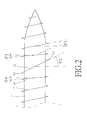
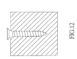
- Fig. 12 an operation about screwing a prior art screw is illustrated. It is illustrated that the screw is screwed into a work piece with a constant orientation. It results that the screw is tightly clamped by the work piece so that the friction force is larger and thus the screwing work is difficult. When the screw is longer, the difficulty in locking the screw is enhanced.
- the primary object of the present invention is to provide a screw with a plurality of screwing angles which comprises a first section having a first thread with a first screwing angle, at least one third section having a second thread with a second screwing angle; and a fifth section having a first thread with a first screwing angle.
- the second screwing angle is equal or not equal to the first screwing angle
- screw further comprises a second section connected between the first section and the third section; the second section having a fourth thread with a fourth screwing angle; a fourth section connected between the third section and the fifth section; and the fourth section having a third thread with a third screwing angle.
- a mold device for forming the screw is also included.
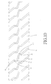
- the screw 1 of the present invention includes a first section 51 having a first thread 11 with a first screwing angle ⁇ 1, and at least one third section 53 having a second thread 12 with a second screwing angle ⁇ 2 and a fifth section 55 having a fifth thread 15 with the first screwing angle ⁇ 1 which the identical to that in the first section I.
- the fifth thread 15 is identical the first thread 11, namely, they have the same thread pitch and screwing angle.
- the second screwing angle ⁇ 2 is not equal to the first screwing angle ⁇ 1.
- the second screwing angle ⁇ 1 is larger than the first screwing angle ⁇ 1 or the second screwing angle ⁇ 2 is smaller than the first screwing angle ⁇ 1.
- a second section 52 is connected between the first section 51 and the third section 53.
- the second section 52 has a fourth thread 14 with fourth screwing angle ⁇ 4.
- a fourth section 54 is connected between the third section 53 and the fifth section 55.
- the fourth section 54 has a third thread 13 with a third screwing angle ⁇ 3.
- the third screwing angle ⁇ 3 is smaller than the first screwing angle ⁇ 1 and / or the fourth screwing angle ⁇ 4 is smaller than the first screwing angle ⁇ 1.
- the thread pitch of the second thread' 12 is 150 to 170 % of the thread pitch of the first thread 11, and the thread pitch of the third thread 13 and /or the fourth screwing angle ⁇ 4 is 67 to 75 % of that of the first thread 11.
- the thread pitch of the second thread 12 is 30 to 50 % of the first thread 11; and the thread pitch of the third thread 13 and / or fourth thread 14 is 125 to 135 % of that of the first thread 11.
- the third screwing angle ⁇ 3 is equal or unequal to the fourth screwing angle ⁇ 4.
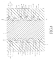
- the fifth section 55 is firstly enters into the work piece, and the fifth thread 15 identical to the first thread 11 serves to cut into a work piece, where indication A in Fig. 4 is a cut screw channel.
- the channel A will be enlarged at one side so as to be form an enlarged portion A1 due to the third screwing angle ⁇ 3 of the third thread 13 different from the first screwing angle ⁇ 1 as the dashed line shown in Fig. 4.
- the channel A is further enlarged at another side so as to form another enlarged portion A2.
- the fourth thread 14 enters into the work piece.
- the channel is further enlarged to a proper width as the indication A2 shown in Fig. 4.
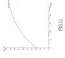
- the test result is illustrated. It is illustrated the larger twisting force of the screw of the present invention is at a point of about 2.0 to 2.5 cm with an average twisting force of 34.2 kg/cm. Then, after the portion of the screw after that point, the twisting force is normal. This means that when a long screw is used, less power is necessary. The required twisting force will not increase due to the increment of length of the screw.
- the present invention can save a force of 25 % than the prior art.
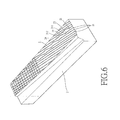
- a mold 2 for forming a screw with a plurality of screw angle comprises a first mold which has a plurality of recesses 61 approximately arranged in parallel.
- Each recess 61 includes two first sloped recesses 21 for forming the first thread I I with a first screwing angle ⁇ 1 and a second sloped recess 22 for forming the second thread 12 with a second screwing angle ⁇ 2.
- the second sloped recess 22 is connected between the two first sloped recesses 21.
- the orientation of the second sloped recess 22 is different from that of the first sloped recesses 21.
- the first mold further includes a third sloped recess 23 connected between one of the first sloped recess 21 and the second sloped recess 22 so as to be an input end and a fourth sloped trench 24 connected between the other one of the first sloped recess 21 and the second sloped recess 22 so as to be as an output end.
- the orientations of the third sloped recess 23 and the fourth sloped trench 24 may be identical or different.
- the absolute value of the slope of the third sloped recess 23 is identical to or different from the slope of the fourth sloped trench 24.
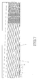
- the slope of the orientation of the second sloped recess 22 is larger than that of the first sloped recess 21, as shown in Fig. 9 or the slope of the orientation of the second sloped recess 22 is smaller than that of the first sloped recess 21, as shown in Fig. 10.
- the mold further comprises a second mold.
- the second mold is symmetrical to the first mold, as shown in Fig. 8.
Landscapes
- Engineering & Computer Science (AREA)
- General Engineering & Computer Science (AREA)
- Mechanical Engineering (AREA)
- Dispersion Chemistry (AREA)
- Wood Science & Technology (AREA)
- Life Sciences & Earth Sciences (AREA)
- Chemical & Material Sciences (AREA)
- Physics & Mathematics (AREA)
- Geometry (AREA)
- Moulds For Moulding Plastics Or The Like (AREA)
- Extrusion Moulding Of Plastics Or The Like (AREA)
- Transmission Devices (AREA)
- Injection Moulding Of Plastics Or The Like (AREA)
Priority Applications (4)
| Application Number | Priority Date | Filing Date | Title |
|---|---|---|---|
| US10/762,139 US7044702B2 (en) | 2004-01-22 | 2004-01-22 | Screw with a plurality of screwing angles and mold device for forming the same |
| EP04001601A EP1557575B1 (de) | 2004-01-22 | 2004-01-26 | Schraube mit einer Vielzahl von Schraubwinkeln und Walzbacken zu ihrer Herstellung |
| AT04001601T ATE350592T1 (de) | 2004-01-22 | 2004-01-26 | Schraube mit einer vielzahl von schraubwinkeln und walzbacken zu ihrer herstellung |
| DE602004004057T DE602004004057T2 (de) | 2004-01-26 | 2004-01-26 | Schraube mit einer Vielzahl von Schraubwinkeln und Walzbacken zu ihrer Herstellung |
Applications Claiming Priority (2)
| Application Number | Priority Date | Filing Date | Title |
|---|---|---|---|
| US10/762,139 US7044702B2 (en) | 2004-01-22 | 2004-01-22 | Screw with a plurality of screwing angles and mold device for forming the same |
| EP04001601A EP1557575B1 (de) | 2004-01-22 | 2004-01-26 | Schraube mit einer Vielzahl von Schraubwinkeln und Walzbacken zu ihrer Herstellung |
Publications (2)
| Publication Number | Publication Date |
|---|---|
| EP1557575A1 true EP1557575A1 (de) | 2005-07-27 |
| EP1557575B1 EP1557575B1 (de) | 2007-01-03 |
Family
ID=34921297
Family Applications (1)
| Application Number | Title | Priority Date | Filing Date |
|---|---|---|---|
| EP04001601A Expired - Lifetime EP1557575B1 (de) | 2004-01-22 | 2004-01-26 | Schraube mit einer Vielzahl von Schraubwinkeln und Walzbacken zu ihrer Herstellung |
Country Status (3)
| Country | Link |
|---|---|
| US (1) | US7044702B2 (de) |
| EP (1) | EP1557575B1 (de) |
| AT (1) | ATE350592T1 (de) |
Families Citing this family (5)
| Publication number | Priority date | Publication date | Assignee | Title |
|---|---|---|---|---|
| ES2370841T3 (es) * | 2005-10-28 | 2011-12-23 | Medartis Ag | Tornillo para formar roscas. |
| US20070128001A1 (en) * | 2005-12-07 | 2007-06-07 | Guo-Cai Su | Screw with two types of threads |
| US20080080951A1 (en) * | 2006-09-07 | 2008-04-03 | Teng-Hung Lin | Screw with a drilling tail |
| US9095444B2 (en) | 2009-07-24 | 2015-08-04 | Warsaw Orthopedic, Inc. | Implant with an interference fit fastener |
| DE102013114653A1 (de) * | 2013-10-15 | 2015-04-16 | Ludwig Hettich & Co. Kg | Verankerungssystem mit einem Hülsenelement und einem Spreizelement |
Citations (5)
| Publication number | Priority date | Publication date | Assignee | Title |
|---|---|---|---|---|
| US3246556A (en) * | 1965-02-08 | 1966-04-19 | Res Eng & Mfg | Self-tapping threaded fasteners |
| US3682507A (en) * | 1970-06-02 | 1972-08-08 | Illinois Tool Works | Threaded fastener with stabilizing threads |
| AU494077B2 (en) * | 1975-03-21 | 1977-10-13 | W.A. Deutsher Pty Ltd | An improved screw |
| CH689214A5 (de) * | 1993-11-23 | 1998-12-15 | Toproc Ag | Befestigungselement zum Eintreiben in vorrangig weiche Werkstoffe und Verbundteile. |
| US6030162A (en) * | 1998-12-18 | 2000-02-29 | Acumed, Inc. | Axial tension screw |
Family Cites Families (14)
| Publication number | Priority date | Publication date | Assignee | Title |
|---|---|---|---|---|
| US3799229A (en) * | 1971-10-26 | 1974-03-26 | Keystone Consolidated Ind Inc | Locking thread fastener |
| US3966341A (en) * | 1974-12-16 | 1976-06-29 | Joy Manufacturing Company | Drill steel |
| DE3607417A1 (de) * | 1986-03-06 | 1987-09-24 | Braas & Co Gmbh | Selbstschneidende schraube |
| US4844676A (en) * | 1986-10-23 | 1989-07-04 | Pheoll Manufacturing Company, Inc. | Self-penetrating screw |
| JPH041371Y2 (de) * | 1987-02-16 | 1992-01-17 | ||
| GB8721048D0 (en) * | 1987-09-08 | 1987-10-14 | Itw Ltd | Screw threaded fastener |
| JPH0716090Y2 (ja) * | 1989-09-12 | 1995-04-12 | 山喜産業株式会社 | タッピングねじ |
| IT1237496B (it) * | 1989-10-26 | 1993-06-08 | Giuseppe Vrespa | Dispositivo a vite per l'ancoraggio di protesi alle ossa, metodo per l'applicazione di tale dispositivo e relativa attrezzatura |
| DE4216197C2 (de) * | 1992-05-15 | 1994-11-10 | Sfs Ind Holding Ag | Schraube |
| DE19608859A1 (de) * | 1996-03-07 | 1997-09-11 | Hilti Ag | Ankerstange für Verbundanker |
| DE69711336T2 (de) * | 1996-11-29 | 2002-10-10 | Max Co. Ltd., Tokio/Tokyo | Selbstschneidende Schraube |
| US6000892A (en) * | 1998-12-11 | 1999-12-14 | Yao Seibyo Kabushiki Kaisha | Wood screw |
| FR2792521B1 (fr) * | 1999-04-22 | 2001-08-31 | New Deal | Vis d'osteosynthese a compression et ancillaire de mise en oeuvre |
| US20030059277A1 (en) * | 2001-09-21 | 2003-03-27 | O'berry Patrick Brian | Double pitch screw |
-
2004
- 2004-01-22 US US10/762,139 patent/US7044702B2/en not_active Expired - Lifetime
- 2004-01-26 EP EP04001601A patent/EP1557575B1/de not_active Expired - Lifetime
- 2004-01-26 AT AT04001601T patent/ATE350592T1/de not_active IP Right Cessation
Patent Citations (5)
| Publication number | Priority date | Publication date | Assignee | Title |
|---|---|---|---|---|
| US3246556A (en) * | 1965-02-08 | 1966-04-19 | Res Eng & Mfg | Self-tapping threaded fasteners |
| US3682507A (en) * | 1970-06-02 | 1972-08-08 | Illinois Tool Works | Threaded fastener with stabilizing threads |
| AU494077B2 (en) * | 1975-03-21 | 1977-10-13 | W.A. Deutsher Pty Ltd | An improved screw |
| CH689214A5 (de) * | 1993-11-23 | 1998-12-15 | Toproc Ag | Befestigungselement zum Eintreiben in vorrangig weiche Werkstoffe und Verbundteile. |
| US6030162A (en) * | 1998-12-18 | 2000-02-29 | Acumed, Inc. | Axial tension screw |
Also Published As
| Publication number | Publication date |
|---|---|
| US7044702B2 (en) | 2006-05-16 |
| US20050163596A1 (en) | 2005-07-28 |
| EP1557575B1 (de) | 2007-01-03 |
| ATE350592T1 (de) | 2007-01-15 |
Similar Documents
| Publication | Publication Date | Title |
|---|---|---|
| KR102238236B1 (ko) | 나사 | |
| US10197086B2 (en) | Threaded fastener | |
| US6676352B2 (en) | Fasteners with improved retaining effect | |
| US20110176889A1 (en) | Concrete and masonry screw anchor | |
| US20100260573A1 (en) | Utility strap | |
| EP1557575A1 (de) | Schraube mit einer Vielzahl von Schraubwinkeln und Walzbacken zu ihrer Herstellung | |
| US3283638A (en) | Socket head screw | |
| US6402449B1 (en) | Screw with an improved head | |
| JPH09184506A (ja) | タッピンねじ | |
| US20040047713A1 (en) | Screwed nail | |
| US7374126B2 (en) | Cable guide of a cable winch | |
| KR20090057498A (ko) | 인서트너트 및 그의 제조방법 | |
| US8297154B2 (en) | Combination wrench with greater strength and torque | |
| CA2947379C (en) | Profile connector and profile assembly | |
| US9982427B2 (en) | Concrete deck insert | |
| US6957557B2 (en) | Threaded fastener with dual reinforcing leads for facilitating manufacture of the fastener, thread rolling die for forming the threaded fastener, and method of manufacturing the threaded fastener | |
| CA2619782C (en) | Fasteners with multi-tiered recesses and drivers with multi-tiered driving tips | |
| KR20090006288A (ko) | 스크류 | |
| CN220049879U (zh) | 一种钢丝绳隔振器成型装置 | |
| US3168941A (en) | Repair key and method of closing cracks | |
| JP3131913U (ja) | タッピンねじ | |
| CN223265537U (zh) | 拧螺母夹具 | |
| US20070031186A1 (en) | Self-clinching D base | |
| CN202914488U (zh) | 一种纤维板钉 | |
| CN108867208A (zh) | 滚道装置 |
Legal Events
| Date | Code | Title | Description |
|---|---|---|---|
| PUAI | Public reference made under article 153(3) epc to a published international application that has entered the european phase |
Free format text: ORIGINAL CODE: 0009012 |
|
| AK | Designated contracting states |
Kind code of ref document: A1 Designated state(s): AT BE BG CH CY CZ DE DK EE ES FI FR GB GR HU IE IT LI LU MC NL PT RO SE SI SK TR |
|
| AX | Request for extension of the european patent |
Extension state: AL LT LV MK |
|
| 17P | Request for examination filed |
Effective date: 20050804 |
|
| AKX | Designation fees paid |
Designated state(s): AT BE BG CH CY CZ DE DK EE ES FI FR GB GR HU IE IT LI LU MC NL PT RO SE SI SK TR |
|
| GRAP | Despatch of communication of intention to grant a patent |
Free format text: ORIGINAL CODE: EPIDOSNIGR1 |
|
| GRAS | Grant fee paid |
Free format text: ORIGINAL CODE: EPIDOSNIGR3 |
|
| GRAA | (expected) grant |
Free format text: ORIGINAL CODE: 0009210 |
|
| AK | Designated contracting states |
Kind code of ref document: B1 Designated state(s): AT BE BG CH CY CZ DE DK EE ES FI FR GB GR HU IE IT LI LU MC NL PT RO SE SI SK TR |
|
| PG25 | Lapsed in a contracting state [announced via postgrant information from national office to epo] |
Ref country code: LI Free format text: LAPSE BECAUSE OF FAILURE TO SUBMIT A TRANSLATION OF THE DESCRIPTION OR TO PAY THE FEE WITHIN THE PRESCRIBED TIME-LIMIT Effective date: 20070103 Ref country code: CH Free format text: LAPSE BECAUSE OF FAILURE TO SUBMIT A TRANSLATION OF THE DESCRIPTION OR TO PAY THE FEE WITHIN THE PRESCRIBED TIME-LIMIT Effective date: 20070103 Ref country code: AT Free format text: LAPSE BECAUSE OF FAILURE TO SUBMIT A TRANSLATION OF THE DESCRIPTION OR TO PAY THE FEE WITHIN THE PRESCRIBED TIME-LIMIT Effective date: 20070103 Ref country code: NL Free format text: LAPSE BECAUSE OF FAILURE TO SUBMIT A TRANSLATION OF THE DESCRIPTION OR TO PAY THE FEE WITHIN THE PRESCRIBED TIME-LIMIT Effective date: 20070103 Ref country code: SI Free format text: LAPSE BECAUSE OF FAILURE TO SUBMIT A TRANSLATION OF THE DESCRIPTION OR TO PAY THE FEE WITHIN THE PRESCRIBED TIME-LIMIT Effective date: 20070103 Ref country code: FI Free format text: LAPSE BECAUSE OF FAILURE TO SUBMIT A TRANSLATION OF THE DESCRIPTION OR TO PAY THE FEE WITHIN THE PRESCRIBED TIME-LIMIT Effective date: 20070103 Ref country code: DK Free format text: LAPSE BECAUSE OF FAILURE TO SUBMIT A TRANSLATION OF THE DESCRIPTION OR TO PAY THE FEE WITHIN THE PRESCRIBED TIME-LIMIT Effective date: 20070103 |
|
| REG | Reference to a national code |
Ref country code: GB Ref legal event code: FG4D |
|
| PG25 | Lapsed in a contracting state [announced via postgrant information from national office to epo] |
Ref country code: IE Free format text: LAPSE BECAUSE OF NON-PAYMENT OF DUE FEES Effective date: 20070126 |
|
| PG25 | Lapsed in a contracting state [announced via postgrant information from national office to epo] |
Ref country code: MC Free format text: LAPSE BECAUSE OF NON-PAYMENT OF DUE FEES Effective date: 20070131 |
|
| REF | Corresponds to: |
Ref document number: 602004004057 Country of ref document: DE Date of ref document: 20070215 Kind code of ref document: P |
|
| REG | Reference to a national code |
Ref country code: IE Ref legal event code: FG4D |
|
| PG25 | Lapsed in a contracting state [announced via postgrant information from national office to epo] |
Ref country code: SE Free format text: LAPSE BECAUSE OF FAILURE TO SUBMIT A TRANSLATION OF THE DESCRIPTION OR TO PAY THE FEE WITHIN THE PRESCRIBED TIME-LIMIT Effective date: 20070403 |
|
| PG25 | Lapsed in a contracting state [announced via postgrant information from national office to epo] |
Ref country code: BG Free format text: LAPSE BECAUSE OF FAILURE TO SUBMIT A TRANSLATION OF THE DESCRIPTION OR TO PAY THE FEE WITHIN THE PRESCRIBED TIME-LIMIT Effective date: 20070404 |
|
| PG25 | Lapsed in a contracting state [announced via postgrant information from national office to epo] |
Ref country code: ES Free format text: LAPSE BECAUSE OF FAILURE TO SUBMIT A TRANSLATION OF THE DESCRIPTION OR TO PAY THE FEE WITHIN THE PRESCRIBED TIME-LIMIT Effective date: 20070414 |
|
| PG25 | Lapsed in a contracting state [announced via postgrant information from national office to epo] |
Ref country code: PT Free format text: LAPSE BECAUSE OF FAILURE TO SUBMIT A TRANSLATION OF THE DESCRIPTION OR TO PAY THE FEE WITHIN THE PRESCRIBED TIME-LIMIT Effective date: 20070604 |
|
| NLV1 | Nl: lapsed or annulled due to failure to fulfill the requirements of art. 29p and 29m of the patents act | ||
| REG | Reference to a national code |
Ref country code: CH Ref legal event code: PL |
|
| EN | Fr: translation not filed | ||
| PLBE | No opposition filed within time limit |
Free format text: ORIGINAL CODE: 0009261 |
|
| STAA | Information on the status of an ep patent application or granted ep patent |
Free format text: STATUS: NO OPPOSITION FILED WITHIN TIME LIMIT |
|
| PG25 | Lapsed in a contracting state [announced via postgrant information from national office to epo] |
Ref country code: SK Free format text: LAPSE BECAUSE OF FAILURE TO SUBMIT A TRANSLATION OF THE DESCRIPTION OR TO PAY THE FEE WITHIN THE PRESCRIBED TIME-LIMIT Effective date: 20070103 |
|
| 26N | No opposition filed |
Effective date: 20071005 |
|
| PG25 | Lapsed in a contracting state [announced via postgrant information from national office to epo] |
Ref country code: CZ Free format text: LAPSE BECAUSE OF FAILURE TO SUBMIT A TRANSLATION OF THE DESCRIPTION OR TO PAY THE FEE WITHIN THE PRESCRIBED TIME-LIMIT Effective date: 20070103 Ref country code: BE Free format text: LAPSE BECAUSE OF FAILURE TO SUBMIT A TRANSLATION OF THE DESCRIPTION OR TO PAY THE FEE WITHIN THE PRESCRIBED TIME-LIMIT Effective date: 20070103 Ref country code: RO Free format text: LAPSE BECAUSE OF FAILURE TO SUBMIT A TRANSLATION OF THE DESCRIPTION OR TO PAY THE FEE WITHIN THE PRESCRIBED TIME-LIMIT Effective date: 20070103 |
|
| PG25 | Lapsed in a contracting state [announced via postgrant information from national office to epo] |
Ref country code: IT Free format text: LAPSE BECAUSE OF FAILURE TO SUBMIT A TRANSLATION OF THE DESCRIPTION OR TO PAY THE FEE WITHIN THE PRESCRIBED TIME-LIMIT Effective date: 20070103 Ref country code: FR Free format text: LAPSE BECAUSE OF FAILURE TO SUBMIT A TRANSLATION OF THE DESCRIPTION OR TO PAY THE FEE WITHIN THE PRESCRIBED TIME-LIMIT Effective date: 20070824 Ref country code: GR Free format text: LAPSE BECAUSE OF FAILURE TO SUBMIT A TRANSLATION OF THE DESCRIPTION OR TO PAY THE FEE WITHIN THE PRESCRIBED TIME-LIMIT Effective date: 20070404 |
|
| GBPC | Gb: european patent ceased through non-payment of renewal fee |
Effective date: 20080126 |
|
| PG25 | Lapsed in a contracting state [announced via postgrant information from national office to epo] |
Ref country code: FR Free format text: LAPSE BECAUSE OF FAILURE TO SUBMIT A TRANSLATION OF THE DESCRIPTION OR TO PAY THE FEE WITHIN THE PRESCRIBED TIME-LIMIT Effective date: 20070103 |
|
| PG25 | Lapsed in a contracting state [announced via postgrant information from national office to epo] |
Ref country code: GB Free format text: LAPSE BECAUSE OF NON-PAYMENT OF DUE FEES Effective date: 20080126 |
|
| PG25 | Lapsed in a contracting state [announced via postgrant information from national office to epo] |
Ref country code: EE Free format text: LAPSE BECAUSE OF FAILURE TO SUBMIT A TRANSLATION OF THE DESCRIPTION OR TO PAY THE FEE WITHIN THE PRESCRIBED TIME-LIMIT Effective date: 20070103 |
|
| PG25 | Lapsed in a contracting state [announced via postgrant information from national office to epo] |
Ref country code: CY Free format text: LAPSE BECAUSE OF FAILURE TO SUBMIT A TRANSLATION OF THE DESCRIPTION OR TO PAY THE FEE WITHIN THE PRESCRIBED TIME-LIMIT Effective date: 20070103 |
|
| PG25 | Lapsed in a contracting state [announced via postgrant information from national office to epo] |
Ref country code: LU Free format text: LAPSE BECAUSE OF NON-PAYMENT OF DUE FEES Effective date: 20070126 |
|
| PG25 | Lapsed in a contracting state [announced via postgrant information from national office to epo] |
Ref country code: TR Free format text: LAPSE BECAUSE OF FAILURE TO SUBMIT A TRANSLATION OF THE DESCRIPTION OR TO PAY THE FEE WITHIN THE PRESCRIBED TIME-LIMIT Effective date: 20070103 Ref country code: HU Free format text: LAPSE BECAUSE OF FAILURE TO SUBMIT A TRANSLATION OF THE DESCRIPTION OR TO PAY THE FEE WITHIN THE PRESCRIBED TIME-LIMIT Effective date: 20070704 |
|
| PGFP | Annual fee paid to national office [announced via postgrant information from national office to epo] |
Ref country code: DE Payment date: 20190130 Year of fee payment: 16 |
|
| REG | Reference to a national code |
Ref country code: DE Ref legal event code: R119 Ref document number: 602004004057 Country of ref document: DE |
|
| PG25 | Lapsed in a contracting state [announced via postgrant information from national office to epo] |
Ref country code: DE Free format text: LAPSE BECAUSE OF NON-PAYMENT OF DUE FEES Effective date: 20200801 |