EP1557575B1 - Vis avec une pluralité de l'angle du vissage et matrice de filetage par roulage pour sa fabrication - Google Patents
Vis avec une pluralité de l'angle du vissage et matrice de filetage par roulage pour sa fabrication Download PDFInfo
- Publication number
- EP1557575B1 EP1557575B1 EP04001601A EP04001601A EP1557575B1 EP 1557575 B1 EP1557575 B1 EP 1557575B1 EP 04001601 A EP04001601 A EP 04001601A EP 04001601 A EP04001601 A EP 04001601A EP 1557575 B1 EP1557575 B1 EP 1557575B1
- Authority
- EP
- European Patent Office
- Prior art keywords
- thread
- section
- helix angle
- screw
- sloped
- Prior art date
- Legal status (The legal status is an assumption and is not a legal conclusion. Google has not performed a legal analysis and makes no representation as to the accuracy of the status listed.)
- Expired - Lifetime
Links
- 238000005096 rolling process Methods 0.000 title abstract 2
- 238000005553 drilling Methods 0.000 description 2
- 239000011810 insulating material Substances 0.000 description 2
- 239000000463 material Substances 0.000 description 2
- 101100439251 Petunia hybrida CHI2 gene Proteins 0.000 description 1
- 230000009286 beneficial effect Effects 0.000 description 1
- 230000007423 decrease Effects 0.000 description 1
- 230000001419 dependent effect Effects 0.000 description 1
- 239000002023 wood Substances 0.000 description 1
Images


Classifications
-
- B—PERFORMING OPERATIONS; TRANSPORTING
- B21—MECHANICAL METAL-WORKING WITHOUT ESSENTIALLY REMOVING MATERIAL; PUNCHING METAL
- B21H—MAKING PARTICULAR METAL OBJECTS BY ROLLING, e.g. SCREWS, WHEELS, RINGS, BARRELS, BALLS
- B21H3/00—Making helical bodies or bodies having parts of helical shape
- B21H3/02—Making helical bodies or bodies having parts of helical shape external screw-threads ; Making dies for thread rolling
- B21H3/027—Rolling of self-tapping screws
-
- F—MECHANICAL ENGINEERING; LIGHTING; HEATING; WEAPONS; BLASTING
- F16—ENGINEERING ELEMENTS AND UNITS; GENERAL MEASURES FOR PRODUCING AND MAINTAINING EFFECTIVE FUNCTIONING OF MACHINES OR INSTALLATIONS; THERMAL INSULATION IN GENERAL
- F16B—DEVICES FOR FASTENING OR SECURING CONSTRUCTIONAL ELEMENTS OR MACHINE PARTS TOGETHER, e.g. NAILS, BOLTS, CIRCLIPS, CLAMPS, CLIPS OR WEDGES; JOINTS OR JOINTING
- F16B25/00—Screws that cut thread in the body into which they are screwed, e.g. wood screws
- F16B25/001—Screws that cut thread in the body into which they are screwed, e.g. wood screws characterised by the material of the body into which the screw is screwed
- F16B25/0015—Screws that cut thread in the body into which they are screwed, e.g. wood screws characterised by the material of the body into which the screw is screwed the material being a soft organic material, e.g. wood or plastic
-
- F—MECHANICAL ENGINEERING; LIGHTING; HEATING; WEAPONS; BLASTING
- F16—ENGINEERING ELEMENTS AND UNITS; GENERAL MEASURES FOR PRODUCING AND MAINTAINING EFFECTIVE FUNCTIONING OF MACHINES OR INSTALLATIONS; THERMAL INSULATION IN GENERAL
- F16B—DEVICES FOR FASTENING OR SECURING CONSTRUCTIONAL ELEMENTS OR MACHINE PARTS TOGETHER, e.g. NAILS, BOLTS, CIRCLIPS, CLAMPS, CLIPS OR WEDGES; JOINTS OR JOINTING
- F16B25/00—Screws that cut thread in the body into which they are screwed, e.g. wood screws
- F16B25/0036—Screws that cut thread in the body into which they are screwed, e.g. wood screws characterised by geometric details of the screw
- F16B25/0042—Screws that cut thread in the body into which they are screwed, e.g. wood screws characterised by geometric details of the screw characterised by the geometry of the thread, the thread being a ridge wrapped around the shaft of the screw
- F16B25/0073—Screws that cut thread in the body into which they are screwed, e.g. wood screws characterised by geometric details of the screw characterised by the geometry of the thread, the thread being a ridge wrapped around the shaft of the screw characterised by its pitch, e.g. a varying pitch
-
- B—PERFORMING OPERATIONS; TRANSPORTING
- B21—MECHANICAL METAL-WORKING WITHOUT ESSENTIALLY REMOVING MATERIAL; PUNCHING METAL
- B21H—MAKING PARTICULAR METAL OBJECTS BY ROLLING, e.g. SCREWS, WHEELS, RINGS, BARRELS, BALLS
- B21H3/00—Making helical bodies or bodies having parts of helical shape
- B21H3/02—Making helical bodies or bodies having parts of helical shape external screw-threads ; Making dies for thread rolling
- B21H3/022—Making helical bodies or bodies having parts of helical shape external screw-threads ; Making dies for thread rolling combined with rolling splines, ribs, grooves or the like, e.g. using compound dies
-
- B—PERFORMING OPERATIONS; TRANSPORTING
- B21—MECHANICAL METAL-WORKING WITHOUT ESSENTIALLY REMOVING MATERIAL; PUNCHING METAL
- B21H—MAKING PARTICULAR METAL OBJECTS BY ROLLING, e.g. SCREWS, WHEELS, RINGS, BARRELS, BALLS
- B21H3/00—Making helical bodies or bodies having parts of helical shape
- B21H3/02—Making helical bodies or bodies having parts of helical shape external screw-threads ; Making dies for thread rolling
- B21H3/06—Making by means of profiled members other than rolls, e.g. reciprocating flat dies or jaws, moved longitudinally or curvilinearly with respect to each other
-
- F—MECHANICAL ENGINEERING; LIGHTING; HEATING; WEAPONS; BLASTING
- F16—ENGINEERING ELEMENTS AND UNITS; GENERAL MEASURES FOR PRODUCING AND MAINTAINING EFFECTIVE FUNCTIONING OF MACHINES OR INSTALLATIONS; THERMAL INSULATION IN GENERAL
- F16B—DEVICES FOR FASTENING OR SECURING CONSTRUCTIONAL ELEMENTS OR MACHINE PARTS TOGETHER, e.g. NAILS, BOLTS, CIRCLIPS, CLAMPS, CLIPS OR WEDGES; JOINTS OR JOINTING
- F16B5/00—Joining sheets or plates, e.g. panels, to one another or to strips or bars parallel to them
- F16B5/02—Joining sheets or plates, e.g. panels, to one another or to strips or bars parallel to them by means of fastening members using screw-thread
- F16B5/0275—Joining sheets or plates, e.g. panels, to one another or to strips or bars parallel to them by means of fastening members using screw-thread the screw-threaded element having at least two axially separated threaded portions
Definitions
- the present invention relates to a screw, and particular to a screw according to the preamble of claim 1 as well as to a mold device for forming a screw with a plurality of helix angles.
- a screw of the initially mentioned type is disclosed in CH 689 214 A, December 15, 1998.
- the shank comprises at least a first, a second and a third axially displaced threaded section.
- the first and third threaded section being identically in configuration and the intermediate second threaded section having a different thread pitch or angle than the first and second section.
- the third threaded section is not connected to the immediate threaded section.
- a smooth section is formed between the section and third thread sections.
- a fastener which comprises a root portion, the root portion having a leading end, a trailing end and an elongate axis extending therebetween; and a single continuous thread formed on the root portion and extending between the leading end and the trailing end of the root portion.
- the thread has an outside diameter which, moving from the leading end toward the trailing end, increases over several revolutions, then decreases, then increases again.
- the pitch of the thread is measured between corresponding points on consecutive threads near the leading end and is larger than the pitch of the threads near the trailing end.
- the fastener only has two threaded sections.
- U. S. Patent No. US-A-3 682 507 discloses a screw type fastener, of the type adapted for use with panels comprising insulating material bounded by sheet material on one side.
- the fastener includes three sections of thread convolutions, the first section is located directly beneath the head of the fastener and extend for a short axial distance.
- the second section is located near the drilling point of the fastener and is adapted to fasten to the thick sheet of purling material comprising part of the panel.
- the immediate or third section is utilized to prevent the fastener from falling freely through the insulating material and this prevent possible breaking of the drilling tip or cocking of the fastener out of the perpendicular plane.
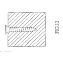
- Fig. 12 the operation about screwing a prior art screw having a thread with unique orientation is illustrated. It is illustrated that the screw is screwed into a work piece with a constant orientation. It results that the screw is tightly clamped by the work piece so that the friction force is larger and thus the screwing work is difficult. When the screw is longer, the difficulty in locking the screw is enhanced.
- the primary object of the present invention is to provide a screw which requires a smaller twisting force for screwing into a work piece.
- the screw comprises a first section having a first thread with a first helix angle, at least one third section having a second thread with a second helix angle; and a fifth section having a fifth thread and the first helix angle.
- the second helix angle is not equal to the first helix angle.
- screw further comprises a second section connected between the first section and the third section; the second section having a fourth thread with a fourth helix angle; a fourth section connected between the third section and the fifth section; and the fourth section having a third thread with a third helix angle.
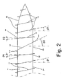
- the screw 1 of the present invention includes a first section 51 having a first thread 11 with a first helix angle ⁇ 1, and at least one third section 53 having a second thread 12 with a second helix-angle ⁇ 2 and a fifth section 55 having a fifth thread 15 with the first helix angle ⁇ 1 which is identical to that in the first section 51.
- the fifth thread 15 is identical to the first thread 11, namely, it has the same thread pitch and helix angle.
- the second helix angle ⁇ 2 is not equal to the first helix angle ⁇ 1.
- the second helix angle ⁇ 2 is larger than the first helix angle ⁇ 1 (see Fig. 2), or the second helix angle ⁇ 2 is smaller than the first helix angle ⁇ 1 (see Fig. 3).
- a second section 52 is connected between the first section 51 and the third section 53.
- the second section 52 has a fourth thread 14 with a fourth helix angle ⁇ 4.
- a fourth section 54 is connected between the third section 53 and the fifth section 55.
- the fourth section 54 has a third thread 13 with a third helix angle ⁇ 3.
- the third helix angle ⁇ 3 is smaller than (referring to Fig. 2) or larger than (referring to Fig. 3) the first helix angle ⁇ 1, and / or the fourth helix angle ⁇ 4 is smaller than (referring to Fig. 2) or larger than (referring to Fig. 3) the first helix angle ⁇ 1.
- the indication 111 in Fig. 2 illustrates the area between the sections 53 and 55
- the indication 112 in Fig. 2 illustrates the area between the sections 51 and 53.
- the thread pitch of the second thread 12 is 150 to 170 % of the thread pitch of the first thread 11, and the thread pitch of the third thread 13 and / or the fourth thread 14 is 67 to 75 % of that of the first thread 11.
- the thread pitch of the second thread 12 is 30 to 50 % of the first thread 11; and the thread pitch of the third thread 13 and / or fourth thread 14 is 125 to 135 % of that of the first thread 11.
- the third helix angle ⁇ 3 is equal or unequal to the fourth helix angle ⁇ 4.
- the fifth section 55 firstly moves into the work piece, and the fifth thread 15 identical to the first thread 11 serves to cut the work piece, where indication A in Fig. 4 is a cut screw channel.
- the channel A will be enlarged at one side so as to be form an enlarged portion Al due to the third helix angle ⁇ 3 of the third thread 13 different from the first helix angle ⁇ 1 as the dashed line shown in Fig. 4.
- the channel A is further enlarged at another side so as to form another enlarged portion A2.
- the fourth thread 14 enters into the work piece.
- the channel is further enlarged to a proper width as the indication A2 shown in Fig. 4.
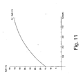
- test object CHIB wood screw.
- the test result is illustrated. It is illustrated the larger twisting force of the screw of the present invention is at a depth of the thread of about 2.0 to 2.5 cm with an average twisting force of 34.2 kgf-cm. Then, after the portion of the screw after that point, the twisting force is normal. This means that when a long screw is used, less power is necessary. The required twisting force will not increase due to the increment of length of the screw.
- the present invention can save a force of 25 % than the prior art.
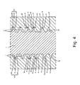
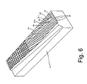
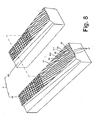
- a mold 2 for forming a screw with a plurality of screw angle comprises a first mold 20 which has a plurality of recesses 61 (see Fig. 8) approximately arranged in parallel.
- Each recess 61 includes two first sloped recesses 21 for forming the first thread I I with a first helix angle ⁇ 1 and a second sloped recess 22 for forming the second thread 12 with a second helix angle ⁇ 2.
- the second sloped recess 22 is connected between the two first sloped recesses 21.
- the orientation of the second sloped recess 22 is different from that of the first sloped recesses 21.
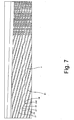
- the first mold 20 further includes a third sloped recess 23 connected between one of the first sloped recess 21 and the second sloped recess 22 (the indications 211 and 212 illustrate the connections of the third sloped recess 23 with other recesses) so as to be an input end and a fourth sloped trench 24 connected between the other one of the first sloped recess 21 and the second sloped recess 22 so as to be as an output end.
- the orientations of the third sloped recess 23 and the fourth sloped trench 24 may be identical or different.
- the absolute value of the slope of the orientation of the third sloped recess 23 is identical to or different from the slope of the orientation of the fourth sloped trench 24.
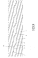
- the slope of the orientation of the second sloped recess 22 is larger than that of the first sloped recess 21, as shown in Fig. 9, or the slope of the orientation of the second sloped recess 22 is smaller than that of the first sloped recess 21, as shown in Fig. 10.
- the mold 2 further comprises a second mold 201.
- the second mold is symmetrical to the first mold, as shown in Fig. 8.
Landscapes
- Engineering & Computer Science (AREA)
- General Engineering & Computer Science (AREA)
- Mechanical Engineering (AREA)
- Dispersion Chemistry (AREA)
- Wood Science & Technology (AREA)
- Life Sciences & Earth Sciences (AREA)
- Chemical & Material Sciences (AREA)
- Physics & Mathematics (AREA)
- Geometry (AREA)
- Moulds For Moulding Plastics Or The Like (AREA)
- Extrusion Moulding Of Plastics Or The Like (AREA)
- Transmission Devices (AREA)
- Injection Moulding Of Plastics Or The Like (AREA)
Claims (13)
- Vis présentant une pluralité d'angles hélicoïdaux comprenant :une première partie (51) comportant un premier filetage (11) présentant un premier angle hélicoïdal (θ1) ;au moins une troisième partie (53) comportant un deuxième filetage (12) présentant un deuxième angle hélicoïdal (θ2);et une cinquième partie (55) comportant un cinquième filetage (15) présentant le premier angle hélicoïdal (θ1); et le cinquième filetage (15) ayant le même pas de filetage que celui du premier filetage (11) ;dans laquelle le deuxième angle hélicoïdal (θ2) n'est pas égal au premier angle hélicoïdal (θ1),caractérisé en ce qu'une deuxième partie (52) est reliée entre la première partie (51) et la troisième partie (53) ; la deuxième partie (52) comporte un quatrième filetage (14) présentant un quatrième angle hélicoïdal (θ4); une quatrième partie (54) est reliée entre la troisième partie (53) et la cinquième partie (55) ; et la quatrième partie (54) comporte un troisième filetage (13) présentant un troisième angle hélicoïdal (θ3).
- Vis présentant une pluralité d'angles hélicoïdaux selon la revendication 1, dans laquelle le troisième angle hélicoïdal (θ3) est inférieur ou supérieur au premier angle hélicoïdal (θ1).
- Vis présentant une pluralité d'angles hélicoïdaux selon la revendication 1 ou 2, dans laquelle le quatrième angle hélicoïdal (θ4) est inférieur ou supérieur au premier angle hélicoïdal (θ1).
- Vis présentant une pluralité d'angles hélicoïdaux selon la revendication 1, dans laquelle le pas de filetage du deuxième filetage (12) est de 150 à 170 % du pas de filetage du premier filetage (11), et le pas de filetage du troisième filetage (13) et/ou du quatrième filetage (14) est de 67 à 75 % du pas de filetage du premier filetage (11).
- Vis présentant une pluralité d'angles hélicoïdaux selon la revendication 1, dans laquelle le pas de filetage du deuxième filetage (12) est de 30 à 50 % du pas du premier filetage (11) et le pas de filetage du troisième filetage (13) et/ou du quatrième filetage (14) est de 125 à 135 % du pas du premier filetage (11).
- Vis présentant une pluralité d'angles hélicoïdaux selon l'une quelconque des revendications 1 à 5, dans laquelle le troisième angle hélicoïdal (θ3) est égal au quatrième angle hélicoïdal (θ4).
- Vis présentant une pluralité d'angles hélicoïdaux selon l'une quelconque des revendications 1 à 5, dans laquelle le troisième angle hélicoïdal (θ3) n'est pas égal au quatrième angle hélicoïdal (θ4).
- Dispositif de moulage pour fabriquer une vis selon l'une quelconque des revendications 1 à 7 présentant une pluralité d'angles hélicoïdaux comprenant :un premier moule comportant une pluralité d'évidements qui sont agencés approximativement en parallèle, chaque évidement (61) comprend deux premiers évidements inclinés (21) pour former un premier filetage (11) et un cinquième filetage (15) présentant respectivement un premier angle hélicoïdal (θ1), le cinquième filetage (15) ayant le même pas de filetage que celui du premier filetage (11), un deuxième évidement incliné (22) pour former un deuxième filetage (12) présentant un deuxième angle hélicoïdal (θ2), le deuxième angle hélicoïdal (θ2) n'étant pas égal au premier angle hélicoïdal (θ1), un troisième évidement incliné (23) relié entre celui des premiers évidements inclinés (21) qui forme le premier filetage (11) et le deuxième évidement incliné (22) pour former un quatrième filetage (14) présentant un quatrième angle hélicoïdal (θ4), et une quatrième tranchée inclinée (24) reliée entre l'autre des premiers évidements inclinés (21) et le deuxième évidement (22) pour former un troisième filetage (13) présentant un troisième angle hélicoïdal (θ3).
- Dispositif de moulage selon la revendication 8, comprenant, en outre :un deuxième moule (201) symétrique par rapport à une ligne au premier moule (20), c'est-à-dire que, lorsqu'une ligne virtuelle est placée le premier moule (20) et le deuxième moule (201), les premier et deuxième moules (20, 201) sont symétriques par rapport à la ligne virtuelle.
- Dispositif de moulage selon la revendication 9, dans lequel, lorsque l'orientation du premier évidement incliné (21) est définie comme étant une direction horizontale, la valeur absolue de la pente du troisième évidement incliné (23) est identique à la valeur absolue de la pente de la quatrième tranchée inclinée (24).
- Dispositif de moulage selon la revendication 9, dans lequel, lorsque l'orientation du premier évidement incliné (21) est définie comme étant une direction horizontale, la valeur absolue de la pente du troisième évidement incliné (23) est différente de la valeur absolue de la pente de la quatrième tranchée inclinée (24).
- Dispositif de moulage selon l'une quelconque des revendications 8 à 11, dans lequel la pente de l'orientation du deuxième évidement incliné (22) est supérieure à celle du premier évidement incliné (21).
- Dispositif de moulage selon l'une quelconque des revendications 8 à 11, dans lequel la pente de l'orientation du deuxième évidement incliné (22) est inférieure à celle du premier évidement incliné (21).
Priority Applications (4)
| Application Number | Priority Date | Filing Date | Title |
|---|---|---|---|
| US10/762,139 US7044702B2 (en) | 2004-01-22 | 2004-01-22 | Screw with a plurality of screwing angles and mold device for forming the same |
| EP04001601A EP1557575B1 (fr) | 2004-01-22 | 2004-01-26 | Vis avec une pluralité de l'angle du vissage et matrice de filetage par roulage pour sa fabrication |
| AT04001601T ATE350592T1 (de) | 2004-01-22 | 2004-01-26 | Schraube mit einer vielzahl von schraubwinkeln und walzbacken zu ihrer herstellung |
| DE602004004057T DE602004004057T2 (de) | 2004-01-26 | 2004-01-26 | Schraube mit einer Vielzahl von Schraubwinkeln und Walzbacken zu ihrer Herstellung |
Applications Claiming Priority (2)
| Application Number | Priority Date | Filing Date | Title |
|---|---|---|---|
| US10/762,139 US7044702B2 (en) | 2004-01-22 | 2004-01-22 | Screw with a plurality of screwing angles and mold device for forming the same |
| EP04001601A EP1557575B1 (fr) | 2004-01-22 | 2004-01-26 | Vis avec une pluralité de l'angle du vissage et matrice de filetage par roulage pour sa fabrication |
Publications (2)
| Publication Number | Publication Date |
|---|---|
| EP1557575A1 EP1557575A1 (fr) | 2005-07-27 |
| EP1557575B1 true EP1557575B1 (fr) | 2007-01-03 |
Family
ID=34921297
Family Applications (1)
| Application Number | Title | Priority Date | Filing Date |
|---|---|---|---|
| EP04001601A Expired - Lifetime EP1557575B1 (fr) | 2004-01-22 | 2004-01-26 | Vis avec une pluralité de l'angle du vissage et matrice de filetage par roulage pour sa fabrication |
Country Status (3)
| Country | Link |
|---|---|
| US (1) | US7044702B2 (fr) |
| EP (1) | EP1557575B1 (fr) |
| AT (1) | ATE350592T1 (fr) |
Families Citing this family (5)
| Publication number | Priority date | Publication date | Assignee | Title |
|---|---|---|---|---|
| ES2370841T3 (es) * | 2005-10-28 | 2011-12-23 | Medartis Ag | Tornillo para formar roscas. |
| US20070128001A1 (en) * | 2005-12-07 | 2007-06-07 | Guo-Cai Su | Screw with two types of threads |
| US20080080951A1 (en) * | 2006-09-07 | 2008-04-03 | Teng-Hung Lin | Screw with a drilling tail |
| US9095444B2 (en) | 2009-07-24 | 2015-08-04 | Warsaw Orthopedic, Inc. | Implant with an interference fit fastener |
| DE102013114653A1 (de) * | 2013-10-15 | 2015-04-16 | Ludwig Hettich & Co. Kg | Verankerungssystem mit einem Hülsenelement und einem Spreizelement |
Family Cites Families (19)
| Publication number | Priority date | Publication date | Assignee | Title |
|---|---|---|---|---|
| NL6408951A (fr) * | 1965-02-08 | 1966-02-07 | ||
| US3682507A (en) * | 1970-06-02 | 1972-08-08 | Illinois Tool Works | Threaded fastener with stabilizing threads |
| US3799229A (en) * | 1971-10-26 | 1974-03-26 | Keystone Consolidated Ind Inc | Locking thread fastener |
| US3966341A (en) * | 1974-12-16 | 1976-06-29 | Joy Manufacturing Company | Drill steel |
| AU494077B2 (en) * | 1975-03-21 | 1977-10-13 | W.A. Deutsher Pty Ltd | An improved screw |
| DE3607417A1 (de) * | 1986-03-06 | 1987-09-24 | Braas & Co Gmbh | Selbstschneidende schraube |
| US4844676A (en) * | 1986-10-23 | 1989-07-04 | Pheoll Manufacturing Company, Inc. | Self-penetrating screw |
| JPH041371Y2 (fr) * | 1987-02-16 | 1992-01-17 | ||
| GB8721048D0 (en) * | 1987-09-08 | 1987-10-14 | Itw Ltd | Screw threaded fastener |
| JPH0716090Y2 (ja) * | 1989-09-12 | 1995-04-12 | 山喜産業株式会社 | タッピングねじ |
| IT1237496B (it) * | 1989-10-26 | 1993-06-08 | Giuseppe Vrespa | Dispositivo a vite per l'ancoraggio di protesi alle ossa, metodo per l'applicazione di tale dispositivo e relativa attrezzatura |
| DE4216197C2 (de) * | 1992-05-15 | 1994-11-10 | Sfs Ind Holding Ag | Schraube |
| US6030162A (en) * | 1998-12-18 | 2000-02-29 | Acumed, Inc. | Axial tension screw |
| CH689214A5 (de) * | 1993-11-23 | 1998-12-15 | Toproc Ag | Befestigungselement zum Eintreiben in vorrangig weiche Werkstoffe und Verbundteile. |
| DE19608859A1 (de) * | 1996-03-07 | 1997-09-11 | Hilti Ag | Ankerstange für Verbundanker |
| DE69711336T2 (de) * | 1996-11-29 | 2002-10-10 | Max Co. Ltd., Tokio/Tokyo | Selbstschneidende Schraube |
| US6000892A (en) * | 1998-12-11 | 1999-12-14 | Yao Seibyo Kabushiki Kaisha | Wood screw |
| FR2792521B1 (fr) * | 1999-04-22 | 2001-08-31 | New Deal | Vis d'osteosynthese a compression et ancillaire de mise en oeuvre |
| US20030059277A1 (en) * | 2001-09-21 | 2003-03-27 | O'berry Patrick Brian | Double pitch screw |
-
2004
- 2004-01-22 US US10/762,139 patent/US7044702B2/en not_active Expired - Lifetime
- 2004-01-26 EP EP04001601A patent/EP1557575B1/fr not_active Expired - Lifetime
- 2004-01-26 AT AT04001601T patent/ATE350592T1/de not_active IP Right Cessation
Also Published As
| Publication number | Publication date |
|---|---|
| US7044702B2 (en) | 2006-05-16 |
| US20050163596A1 (en) | 2005-07-28 |
| EP1557575A1 (fr) | 2005-07-27 |
| ATE350592T1 (de) | 2007-01-15 |
Similar Documents
| Publication | Publication Date | Title |
|---|---|---|
| EP2679835B1 (fr) | Élément de fixation fileté | |
| US6796761B2 (en) | Bolt and nut | |
| US5088869A (en) | Thread rolling screw | |
| EP2286097B1 (fr) | Élément de fixation fileté | |
| US4601625A (en) | Self drilling threaded insert for drywall | |
| US8444360B2 (en) | Self-drilling screw | |
| US20170108026A1 (en) | Screw | |
| US5772374A (en) | Tapping screw and mechanism of engaging member to be engaged using the same | |
| EP1557575B1 (fr) | Vis avec une pluralité de l'angle du vissage et matrice de filetage par roulage pour sa fabrication | |
| US5909992A (en) | Self-tapping screw for fastening a metal corrugated board | |
| US20040047713A1 (en) | Screwed nail | |
| EP1398514B1 (fr) | Structure d'attache par vis | |
| US5667348A (en) | Screw for fibrous boards | |
| IE51170B1 (en) | Self-drilling,self-tapping screws | |
| US9016996B2 (en) | Threaded sleeves | |
| KR20090006288A (ko) | 스크류 | |
| US20230160413A1 (en) | Threaded Fastener With Scalloped Minor Diameter | |
| JP2005003147A (ja) | ドリリングタッピングねじ | |
| GB2359603A (en) | A screw having cutting teeth formed on threads | |
| EP1803945A2 (fr) | Vis à bois | |
| EP3988804B1 (fr) | Vis | |
| KR20050087542A (ko) | 복수의 나선 각도를 갖는 나사 및 그것을 성형하기 위한몰드 장치 | |
| KR200290514Y1 (ko) | 파워스크류못 | |
| US20070122249A1 (en) | Wood screws capable of cutting wood | |
| JPS6327126Y2 (fr) |
Legal Events
| Date | Code | Title | Description |
|---|---|---|---|
| PUAI | Public reference made under article 153(3) epc to a published international application that has entered the european phase |
Free format text: ORIGINAL CODE: 0009012 |
|
| AK | Designated contracting states |
Kind code of ref document: A1 Designated state(s): AT BE BG CH CY CZ DE DK EE ES FI FR GB GR HU IE IT LI LU MC NL PT RO SE SI SK TR |
|
| AX | Request for extension of the european patent |
Extension state: AL LT LV MK |
|
| 17P | Request for examination filed |
Effective date: 20050804 |
|
| AKX | Designation fees paid |
Designated state(s): AT BE BG CH CY CZ DE DK EE ES FI FR GB GR HU IE IT LI LU MC NL PT RO SE SI SK TR |
|
| GRAP | Despatch of communication of intention to grant a patent |
Free format text: ORIGINAL CODE: EPIDOSNIGR1 |
|
| GRAS | Grant fee paid |
Free format text: ORIGINAL CODE: EPIDOSNIGR3 |
|
| GRAA | (expected) grant |
Free format text: ORIGINAL CODE: 0009210 |
|
| AK | Designated contracting states |
Kind code of ref document: B1 Designated state(s): AT BE BG CH CY CZ DE DK EE ES FI FR GB GR HU IE IT LI LU MC NL PT RO SE SI SK TR |
|
| PG25 | Lapsed in a contracting state [announced via postgrant information from national office to epo] |
Ref country code: LI Free format text: LAPSE BECAUSE OF FAILURE TO SUBMIT A TRANSLATION OF THE DESCRIPTION OR TO PAY THE FEE WITHIN THE PRESCRIBED TIME-LIMIT Effective date: 20070103 Ref country code: CH Free format text: LAPSE BECAUSE OF FAILURE TO SUBMIT A TRANSLATION OF THE DESCRIPTION OR TO PAY THE FEE WITHIN THE PRESCRIBED TIME-LIMIT Effective date: 20070103 Ref country code: AT Free format text: LAPSE BECAUSE OF FAILURE TO SUBMIT A TRANSLATION OF THE DESCRIPTION OR TO PAY THE FEE WITHIN THE PRESCRIBED TIME-LIMIT Effective date: 20070103 Ref country code: NL Free format text: LAPSE BECAUSE OF FAILURE TO SUBMIT A TRANSLATION OF THE DESCRIPTION OR TO PAY THE FEE WITHIN THE PRESCRIBED TIME-LIMIT Effective date: 20070103 Ref country code: SI Free format text: LAPSE BECAUSE OF FAILURE TO SUBMIT A TRANSLATION OF THE DESCRIPTION OR TO PAY THE FEE WITHIN THE PRESCRIBED TIME-LIMIT Effective date: 20070103 Ref country code: FI Free format text: LAPSE BECAUSE OF FAILURE TO SUBMIT A TRANSLATION OF THE DESCRIPTION OR TO PAY THE FEE WITHIN THE PRESCRIBED TIME-LIMIT Effective date: 20070103 Ref country code: DK Free format text: LAPSE BECAUSE OF FAILURE TO SUBMIT A TRANSLATION OF THE DESCRIPTION OR TO PAY THE FEE WITHIN THE PRESCRIBED TIME-LIMIT Effective date: 20070103 |
|
| REG | Reference to a national code |
Ref country code: GB Ref legal event code: FG4D |
|
| PG25 | Lapsed in a contracting state [announced via postgrant information from national office to epo] |
Ref country code: IE Free format text: LAPSE BECAUSE OF NON-PAYMENT OF DUE FEES Effective date: 20070126 |
|
| PG25 | Lapsed in a contracting state [announced via postgrant information from national office to epo] |
Ref country code: MC Free format text: LAPSE BECAUSE OF NON-PAYMENT OF DUE FEES Effective date: 20070131 |
|
| REF | Corresponds to: |
Ref document number: 602004004057 Country of ref document: DE Date of ref document: 20070215 Kind code of ref document: P |
|
| REG | Reference to a national code |
Ref country code: IE Ref legal event code: FG4D |
|
| PG25 | Lapsed in a contracting state [announced via postgrant information from national office to epo] |
Ref country code: SE Free format text: LAPSE BECAUSE OF FAILURE TO SUBMIT A TRANSLATION OF THE DESCRIPTION OR TO PAY THE FEE WITHIN THE PRESCRIBED TIME-LIMIT Effective date: 20070403 |
|
| PG25 | Lapsed in a contracting state [announced via postgrant information from national office to epo] |
Ref country code: BG Free format text: LAPSE BECAUSE OF FAILURE TO SUBMIT A TRANSLATION OF THE DESCRIPTION OR TO PAY THE FEE WITHIN THE PRESCRIBED TIME-LIMIT Effective date: 20070404 |
|
| PG25 | Lapsed in a contracting state [announced via postgrant information from national office to epo] |
Ref country code: ES Free format text: LAPSE BECAUSE OF FAILURE TO SUBMIT A TRANSLATION OF THE DESCRIPTION OR TO PAY THE FEE WITHIN THE PRESCRIBED TIME-LIMIT Effective date: 20070414 |
|
| PG25 | Lapsed in a contracting state [announced via postgrant information from national office to epo] |
Ref country code: PT Free format text: LAPSE BECAUSE OF FAILURE TO SUBMIT A TRANSLATION OF THE DESCRIPTION OR TO PAY THE FEE WITHIN THE PRESCRIBED TIME-LIMIT Effective date: 20070604 |
|
| NLV1 | Nl: lapsed or annulled due to failure to fulfill the requirements of art. 29p and 29m of the patents act | ||
| REG | Reference to a national code |
Ref country code: CH Ref legal event code: PL |
|
| EN | Fr: translation not filed | ||
| PLBE | No opposition filed within time limit |
Free format text: ORIGINAL CODE: 0009261 |
|
| STAA | Information on the status of an ep patent application or granted ep patent |
Free format text: STATUS: NO OPPOSITION FILED WITHIN TIME LIMIT |
|
| PG25 | Lapsed in a contracting state [announced via postgrant information from national office to epo] |
Ref country code: SK Free format text: LAPSE BECAUSE OF FAILURE TO SUBMIT A TRANSLATION OF THE DESCRIPTION OR TO PAY THE FEE WITHIN THE PRESCRIBED TIME-LIMIT Effective date: 20070103 |
|
| 26N | No opposition filed |
Effective date: 20071005 |
|
| PG25 | Lapsed in a contracting state [announced via postgrant information from national office to epo] |
Ref country code: CZ Free format text: LAPSE BECAUSE OF FAILURE TO SUBMIT A TRANSLATION OF THE DESCRIPTION OR TO PAY THE FEE WITHIN THE PRESCRIBED TIME-LIMIT Effective date: 20070103 Ref country code: BE Free format text: LAPSE BECAUSE OF FAILURE TO SUBMIT A TRANSLATION OF THE DESCRIPTION OR TO PAY THE FEE WITHIN THE PRESCRIBED TIME-LIMIT Effective date: 20070103 Ref country code: RO Free format text: LAPSE BECAUSE OF FAILURE TO SUBMIT A TRANSLATION OF THE DESCRIPTION OR TO PAY THE FEE WITHIN THE PRESCRIBED TIME-LIMIT Effective date: 20070103 |
|
| PG25 | Lapsed in a contracting state [announced via postgrant information from national office to epo] |
Ref country code: IT Free format text: LAPSE BECAUSE OF FAILURE TO SUBMIT A TRANSLATION OF THE DESCRIPTION OR TO PAY THE FEE WITHIN THE PRESCRIBED TIME-LIMIT Effective date: 20070103 Ref country code: FR Free format text: LAPSE BECAUSE OF FAILURE TO SUBMIT A TRANSLATION OF THE DESCRIPTION OR TO PAY THE FEE WITHIN THE PRESCRIBED TIME-LIMIT Effective date: 20070824 Ref country code: GR Free format text: LAPSE BECAUSE OF FAILURE TO SUBMIT A TRANSLATION OF THE DESCRIPTION OR TO PAY THE FEE WITHIN THE PRESCRIBED TIME-LIMIT Effective date: 20070404 |
|
| GBPC | Gb: european patent ceased through non-payment of renewal fee |
Effective date: 20080126 |
|
| PG25 | Lapsed in a contracting state [announced via postgrant information from national office to epo] |
Ref country code: FR Free format text: LAPSE BECAUSE OF FAILURE TO SUBMIT A TRANSLATION OF THE DESCRIPTION OR TO PAY THE FEE WITHIN THE PRESCRIBED TIME-LIMIT Effective date: 20070103 |
|
| PG25 | Lapsed in a contracting state [announced via postgrant information from national office to epo] |
Ref country code: GB Free format text: LAPSE BECAUSE OF NON-PAYMENT OF DUE FEES Effective date: 20080126 |
|
| PG25 | Lapsed in a contracting state [announced via postgrant information from national office to epo] |
Ref country code: EE Free format text: LAPSE BECAUSE OF FAILURE TO SUBMIT A TRANSLATION OF THE DESCRIPTION OR TO PAY THE FEE WITHIN THE PRESCRIBED TIME-LIMIT Effective date: 20070103 |
|
| PG25 | Lapsed in a contracting state [announced via postgrant information from national office to epo] |
Ref country code: CY Free format text: LAPSE BECAUSE OF FAILURE TO SUBMIT A TRANSLATION OF THE DESCRIPTION OR TO PAY THE FEE WITHIN THE PRESCRIBED TIME-LIMIT Effective date: 20070103 |
|
| PG25 | Lapsed in a contracting state [announced via postgrant information from national office to epo] |
Ref country code: LU Free format text: LAPSE BECAUSE OF NON-PAYMENT OF DUE FEES Effective date: 20070126 |
|
| PG25 | Lapsed in a contracting state [announced via postgrant information from national office to epo] |
Ref country code: TR Free format text: LAPSE BECAUSE OF FAILURE TO SUBMIT A TRANSLATION OF THE DESCRIPTION OR TO PAY THE FEE WITHIN THE PRESCRIBED TIME-LIMIT Effective date: 20070103 Ref country code: HU Free format text: LAPSE BECAUSE OF FAILURE TO SUBMIT A TRANSLATION OF THE DESCRIPTION OR TO PAY THE FEE WITHIN THE PRESCRIBED TIME-LIMIT Effective date: 20070704 |
|
| PGFP | Annual fee paid to national office [announced via postgrant information from national office to epo] |
Ref country code: DE Payment date: 20190130 Year of fee payment: 16 |
|
| REG | Reference to a national code |
Ref country code: DE Ref legal event code: R119 Ref document number: 602004004057 Country of ref document: DE |
|
| PG25 | Lapsed in a contracting state [announced via postgrant information from national office to epo] |
Ref country code: DE Free format text: LAPSE BECAUSE OF NON-PAYMENT OF DUE FEES Effective date: 20200801 |