EP1557580A2 - Valve system for method of controlling a clutch of a motor vehicle - Google Patents
Valve system for method of controlling a clutch of a motor vehicle Download PDFInfo
- Publication number
- EP1557580A2 EP1557580A2 EP05000291A EP05000291A EP1557580A2 EP 1557580 A2 EP1557580 A2 EP 1557580A2 EP 05000291 A EP05000291 A EP 05000291A EP 05000291 A EP05000291 A EP 05000291A EP 1557580 A2 EP1557580 A2 EP 1557580A2
- Authority
- EP
- European Patent Office
- Prior art keywords
- pressure
- valve
- clutch
- actuator
- flow
- Prior art date
- Legal status (The legal status is an assumption and is not a legal conclusion. Google has not performed a legal analysis and makes no representation as to the accuracy of the status listed.)
- Granted
Links
- 238000000034 method Methods 0.000 claims description 21
- 230000001276 controlling effect Effects 0.000 claims description 15
- 230000001105 regulatory effect Effects 0.000 claims description 14
- 230000007257 malfunction Effects 0.000 claims 1
- 230000008859 change Effects 0.000 abstract description 8
- 239000012530 fluid Substances 0.000 abstract 1
- 230000005540 biological transmission Effects 0.000 description 10
- 230000008878 coupling Effects 0.000 description 6
- 238000010168 coupling process Methods 0.000 description 6
- 238000005859 coupling reaction Methods 0.000 description 6
- 230000000694 effects Effects 0.000 description 4
- 230000001419 dependent effect Effects 0.000 description 2
- 238000013461 design Methods 0.000 description 2
- 238000006073 displacement reaction Methods 0.000 description 2
- 238000012423 maintenance Methods 0.000 description 2
- 230000009471 action Effects 0.000 description 1
- 230000004913 activation Effects 0.000 description 1
- 230000008901 benefit Effects 0.000 description 1
- 230000015572 biosynthetic process Effects 0.000 description 1
- 238000011156 evaluation Methods 0.000 description 1
- 238000003780 insertion Methods 0.000 description 1
- 230000037431 insertion Effects 0.000 description 1
- 230000008569 process Effects 0.000 description 1
Images
Classifications
-
- F—MECHANICAL ENGINEERING; LIGHTING; HEATING; WEAPONS; BLASTING
- F16—ENGINEERING ELEMENTS AND UNITS; GENERAL MEASURES FOR PRODUCING AND MAINTAINING EFFECTIVE FUNCTIONING OF MACHINES OR INSTALLATIONS; THERMAL INSULATION IN GENERAL
- F16D—COUPLINGS FOR TRANSMITTING ROTATION; CLUTCHES; BRAKES
- F16D23/00—Details of mechanically-actuated clutches not specific for one distinct type
- F16D23/12—Mechanical clutch-actuating mechanisms arranged outside the clutch as such
-
- F—MECHANICAL ENGINEERING; LIGHTING; HEATING; WEAPONS; BLASTING
- F16—ENGINEERING ELEMENTS AND UNITS; GENERAL MEASURES FOR PRODUCING AND MAINTAINING EFFECTIVE FUNCTIONING OF MACHINES OR INSTALLATIONS; THERMAL INSULATION IN GENERAL
- F16D—COUPLINGS FOR TRANSMITTING ROTATION; CLUTCHES; BRAKES
- F16D48/00—External control of clutches
- F16D48/02—Control by fluid pressure
-
- F—MECHANICAL ENGINEERING; LIGHTING; HEATING; WEAPONS; BLASTING
- F16—ENGINEERING ELEMENTS AND UNITS; GENERAL MEASURES FOR PRODUCING AND MAINTAINING EFFECTIVE FUNCTIONING OF MACHINES OR INSTALLATIONS; THERMAL INSULATION IN GENERAL
- F16D—COUPLINGS FOR TRANSMITTING ROTATION; CLUTCHES; BRAKES
- F16D48/00—External control of clutches
- F16D48/02—Control by fluid pressure
- F16D2048/0221—Valves for clutch control systems; Details thereof
-
- F—MECHANICAL ENGINEERING; LIGHTING; HEATING; WEAPONS; BLASTING
- F16—ENGINEERING ELEMENTS AND UNITS; GENERAL MEASURES FOR PRODUCING AND MAINTAINING EFFECTIVE FUNCTIONING OF MACHINES OR INSTALLATIONS; THERMAL INSULATION IN GENERAL
- F16D—COUPLINGS FOR TRANSMITTING ROTATION; CLUTCHES; BRAKES
- F16D48/00—External control of clutches
- F16D48/02—Control by fluid pressure
- F16D2048/0257—Hydraulic circuit layouts, i.e. details of hydraulic circuit elements or the arrangement thereof
- F16D2048/0266—Actively controlled valves between pressure source and actuation cylinder
-
- F—MECHANICAL ENGINEERING; LIGHTING; HEATING; WEAPONS; BLASTING
- F16—ENGINEERING ELEMENTS AND UNITS; GENERAL MEASURES FOR PRODUCING AND MAINTAINING EFFECTIVE FUNCTIONING OF MACHINES OR INSTALLATIONS; THERMAL INSULATION IN GENERAL
- F16D—COUPLINGS FOR TRANSMITTING ROTATION; CLUTCHES; BRAKES
- F16D2500/00—External control of clutches by electric or electronic means
- F16D2500/10—System to be controlled
- F16D2500/102—Actuator
- F16D2500/1026—Hydraulic
-
- F—MECHANICAL ENGINEERING; LIGHTING; HEATING; WEAPONS; BLASTING
- F16—ENGINEERING ELEMENTS AND UNITS; GENERAL MEASURES FOR PRODUCING AND MAINTAINING EFFECTIVE FUNCTIONING OF MACHINES OR INSTALLATIONS; THERMAL INSULATION IN GENERAL
- F16D—COUPLINGS FOR TRANSMITTING ROTATION; CLUTCHES; BRAKES
- F16D2500/00—External control of clutches by electric or electronic means
- F16D2500/30—Signal inputs
- F16D2500/302—Signal inputs from the actuator
- F16D2500/3023—Force
-
- F—MECHANICAL ENGINEERING; LIGHTING; HEATING; WEAPONS; BLASTING
- F16—ENGINEERING ELEMENTS AND UNITS; GENERAL MEASURES FOR PRODUCING AND MAINTAINING EFFECTIVE FUNCTIONING OF MACHINES OR INSTALLATIONS; THERMAL INSULATION IN GENERAL
- F16D—COUPLINGS FOR TRANSMITTING ROTATION; CLUTCHES; BRAKES
- F16D2500/00—External control of clutches by electric or electronic means
- F16D2500/30—Signal inputs
- F16D2500/302—Signal inputs from the actuator
- F16D2500/3024—Pressure
-
- F—MECHANICAL ENGINEERING; LIGHTING; HEATING; WEAPONS; BLASTING
- F16—ENGINEERING ELEMENTS AND UNITS; GENERAL MEASURES FOR PRODUCING AND MAINTAINING EFFECTIVE FUNCTIONING OF MACHINES OR INSTALLATIONS; THERMAL INSULATION IN GENERAL
- F16D—COUPLINGS FOR TRANSMITTING ROTATION; CLUTCHES; BRAKES
- F16D2500/00—External control of clutches by electric or electronic means
- F16D2500/70—Details about the implementation of the control system
- F16D2500/702—Look-up tables
- F16D2500/70205—Clutch actuator
- F16D2500/70217—Pressure
-
- F—MECHANICAL ENGINEERING; LIGHTING; HEATING; WEAPONS; BLASTING
- F16—ENGINEERING ELEMENTS AND UNITS; GENERAL MEASURES FOR PRODUCING AND MAINTAINING EFFECTIVE FUNCTIONING OF MACHINES OR INSTALLATIONS; THERMAL INSULATION IN GENERAL
- F16D—COUPLINGS FOR TRANSMITTING ROTATION; CLUTCHES; BRAKES
- F16D2500/00—External control of clutches by electric or electronic means
- F16D2500/70—Details about the implementation of the control system
- F16D2500/702—Look-up tables
- F16D2500/70205—Clutch actuator
- F16D2500/70235—Displacement
-
- F—MECHANICAL ENGINEERING; LIGHTING; HEATING; WEAPONS; BLASTING
- F16—ENGINEERING ELEMENTS AND UNITS; GENERAL MEASURES FOR PRODUCING AND MAINTAINING EFFECTIVE FUNCTIONING OF MACHINES OR INSTALLATIONS; THERMAL INSULATION IN GENERAL
- F16D—COUPLINGS FOR TRANSMITTING ROTATION; CLUTCHES; BRAKES
- F16D2500/00—External control of clutches by electric or electronic means
- F16D2500/70—Details about the implementation of the control system
- F16D2500/704—Output parameters from the control unit; Target parameters to be controlled
- F16D2500/70402—Actuator parameters
- F16D2500/70406—Pressure
Definitions
- the invention relates to a valve system for controlling a clutch or a Gear actuator of a motor vehicle, in particular of a dry clutch, with at least one actuator for actuating the clutch, vzw. to the Opening and / or closing the clutch, or to operate the gear selector and at least one tank for providing a hydraulic medium.
- the invention further relates to a method for controlling at least one Clutch or a gear selector of a motor vehicle, in particular of a Dry clutch, wherein at least one actuator for actuating the clutch or is driven to actuate the gear selector and wherein by means of a Tanks a hydraulic medium is provided, and wherein the clutch pressure or the Ganstellerdruck on the adjustment of the clutch or the Gear actuator varies and the tank pressure is substantially constant.
- pressure controls for controlling in particular from dry clutches corresponding "pressure controls" known.
- Pressure control valves or pressure switching valves in use Pressure regulators keep the pressure independent of the size of a higher form or Supply pressure constant, with pressure switching valves when reaching a certain set pressure a current path for another workflow release.
- the forces can be adjusted via the pressure control valves be that the insertion of a gear in the transmission as gently as possible for the Synchronizing rings of a switching device takes place.
- the pressure of pressure control valves via a set screw with lock nut or alternatively via an electrical and / or electronic Control can be influenced individually.
- a displacement control of the clutches is used, wherein the actuator usually moved by a defined amount and thus - at correspondingly stiff components - a relatively well reproducible change adjusts the clutch capacity.
- the flow valves regulate via a throttle effect the speed of movement of the flow medium / hydraulic medium within the hydraulic circuit, thereby enabling one Switching the clutches.
- the invention is therefore based on the object that the aforementioned valve system or the known method for controlling clutches or of Gear actuators to design and develop such that tax and / or Control problems, in particular caused by force hysteresis in almost Any operating situation can be avoided to wear the clutch as well as the transmission, in particular also to reduce the synchronizer rings and thereby extending their service life and subsequent maintenance costs to lower.
- valve system by at least one pressure regulating valve and at least one flow valve in Series connection are arranged in front of the actuator.
- the task for the method is now solved by combining at least one pressure control valve and at least one flow valve in series, the pressure control valve and / or the flow valve in such a way be controlled that the currently applied to the flow valve supply pressure depending on the change over the adjustment clutch pressure or gear actuator pressure is set.
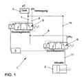
- Fig. 1 is a valve system 1 for controlling a coupling, not shown, in particular of dry clutches of a motor vehicle or to Control of a gear selector of a transmission, not shown, shown.
- the Valve system 1 has at least one actuator 2 for controlling the clutch or the gear selector and a tank 3 for providing a hydraulic medium on.
- a control device 4 with at least one tax technical Connection to the pressure control valve 5 and at least one tax technical Connection to the flow valve 6 is provided.
- the control device 4 is for Evaluation of various parameters formed. A variety of parameters are determinable for the ideal switching of dry clutches or gear actuators, Preferably, the control device 4 processes the engine speed, the gear ratio, the accelerator pedal position, the engine torque, the activities the brake, the transmission temperatures, the pressures or pressure differences etc. via appropriate sensors of the control device 4, the individual Parameter values supplied.
- the pressure regulating valve 5 has at least one first discharge line 7 to the tank 3 and, always to a corresponding supply pressure pV available, a first pressure line 8 to the pressure supply on. There is another connection to the flow valve 6 through a second pressure line 9 is provided. Through a connection of the pressure regulating valve 5 with the flow valve 6 is always the optimized required current Pressure at the flow valve 6 for the respective situation-dependent switching operation ensured or in particular by the control device 4 adjustable.
- the flow valve 6 is connected via the second pressure line 9 with the pressure control valve 5 connected. Furthermore, a second discharge capacity 10 to the tank 3 and a third pressure line 11 to the actuator 2.
- the actuator. 2 operated directly and / or indirectly the clutch or a gear plate of Motor vehicle, preferably via the corresponding displacement of here in 1 in the actuator 2 shown piston.
- the pressure regulating valve 5 is arranged in series connection in front of the flow valve 6.
- an arrangement of the flow valve 6 in series connection in front of the pressure regulating valve 5 is also conceivable.
- What is decisive is the combination of both valve characteristics in series connection or even taking account of the control device 4 for ideal tuning. Due to this fact, the pressure control valve 5 can provide on the second pressure line 9 of the flow valve 6 a current supply pressure pV (S) adapted to the operating situation and thus optimize the switching operation or the activation of the actuator 2.
- the pressure control valve 5 in the leading to the flow valve 6 second pressure line 9 a the respective operating situation adapted specific supply pressure pV (S) ready.
- the pressure control valve 5 controls and / or regulates the existing in the second pressure line 9 supply pressure pV (S) such that this currently at the flow valve 6 applied supply pressure pV (S) as a function of changing over the adjustment s clutch pressure pK (S) or changing gear actuator pressure is set.
- the pressure control valve 5 has vzw. an aperture over which the supply pressure pV (S) present in the second pressure line 9 can be correspondingly adjusted.
- the supply pressure pV (S) applied to the flow valve 6 is adjusted so that the quotient of the differential pressures, namely the difference between the current supply pressure pV (s) and the current clutch pressure pK (S) and from the difference of the current clutch pressure pK (S) or the gear actuator pressure and the tank pressure pT is substantially constant over the adjustment path s substantially.
- the quotient of the differential pressures namely the difference between the current supply pressure pV (s) and the current clutch pressure pK (S) and from the difference of the current clutch pressure pK (S) or the gear actuator pressure and the tank pressure pT is substantially constant over the adjustment path s substantially.
- Fig. 1 shows - as already mentioned - the valve system 1.
- this valve system 1 can now be driven corresponding clutches of a motor vehicle become.
- a corresponding gear actuator of a transmission of a motor vehicle to control accordingly. This depends on the particular application. It is crucial that with the help of the actuator 2 shown here, with the valve system 1 is activated or actuated, corresponding couplings or gear selector can then be operated.
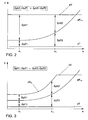
- FIGS. 2 and 3 show the supply pressure pV, the clutch pressure pK (S) , the tank pressure pT and the specifically set supply pressure pV (S) . It can be clearly seen that, in particular, the clutch pressure pK (S) changes as a function of the adjustment path s. As FIG. 2 shows, here the supply pressure pV is essentially constant. The same applies to the tank pressure pT. This is different in comparison to FIG. 3, which will be explained below.
- Fig. 2 are - as known in the art - the differential pressures occurring with respect to the closing and opening direction of a flow valve 6 schematically, without a pressure control valve 5 is connected in series, shown.
- the different differential pressures between the respective switching operations are, for example, the self-adjusting Pressure differences ⁇ pV1, ⁇ pT1, ⁇ pV2 and ⁇ pT2 are indicated by arrows. It is clearly seen that the quotient of the differential pressures, namely ⁇ pV1 / ⁇ pT1> ⁇ pV2 / ⁇ pT2, ie the quotients from the differential pressures are different.
- Fig. 3 the differential pressures in the closing and opening direction of the flow valve 6 with pressure precontrol or tracking by means of the pressure control valve 5 are shown schematically.
- the differential pressures ⁇ pV1, ⁇ pT1, ⁇ pV2, ⁇ pT2 that arise are also identified by corresponding arrows for different adjustment points S 1 and S 2 .
- the control device 4 controls and regulates Pressure control valve 5 and the flow valve 6. Additional parameters such as Engine speed, the transmission input position, the accelerator pedal position, the engine torque, the activities of the brake, the transmission temperatures and others Parameters can be taken into account and processed by the control device 4 become.
- the control device 4 is vzw. as electrical / electronic control device 4 formed, vzw. a corresponding microprocessor.
- the control device 4 is capable of existing in the third pressure line 11 to measure the actual clutch pressure pK (s) or with the help of the pressure control valve 5 and the flow valve 6, both vzw. corresponding apertures have to adjust accordingly. Furthermore, the volume flow by the flow valve 6 by the control device 4 influenced accordingly. Also conceivable is a corresponding change in the volume flow by the control of the flow valve 6 by the control device 4, in order to optimally adjust corresponding pressure differences.
- the actuator 2 is now driven accordingly to actuate the clutch or the gear actuator.
- a hydraulic medium is provided by means of a tank 3, wherein the clutch pressure pK (S) varies over the adjustment path s of the clutch or the gear actuator pressure and the tank pressure pT is substantially constant, as shown in FIGS. 2 and 3.
- the disadvantages described above are avoided.
- a "safety function” is realized.
- the flow valve 6 is no longer controllable and is in a second pressure line 9 with the third pressure line 11 connecting position, for example.
- the help Pressure control valve 5 By pollution or eg.
- the specific supply pressure pV (S) degraded.
- the actuator 2 can be relieved without the main pressure or supply pressure pV must be switched off.
- the specific supply pressure pV (S) can now be partially lowered or completely lowered without the supply pressure pV having to be modified.
- the system With actively closing couplings, the system can be transferred to the safe state "clutch open" without affecting other subfunctions.
- the system could be driven as a pure pressure control with appropriate design of the clutch force characteristic (eg: monotonically increasing). Especially in systems with only one clutch, this would allow emergency operation.
Landscapes
- Engineering & Computer Science (AREA)
- General Engineering & Computer Science (AREA)
- Mechanical Engineering (AREA)
- Physics & Mathematics (AREA)
- Fluid Mechanics (AREA)
- Hydraulic Clutches, Magnetic Clutches, Fluid Clutches, And Fluid Joints (AREA)
Abstract
Description
Die Erfindung betrifft ein Ventilsystem zur Steuerung einer Kupplung oder eines Gangstellers eines Kraftfahrzeuges, insbesondere von einer Trockenkupplung, mit mindestens einem Aktuator zur Betätigung der Kupplung, vzw. zum Öffnen und / oder Schließen der Kupplung, oder zur Betätigung des Gangstellers und mit mindestens einem Tank zur Bereitstellung eines Hydraulikmediums. Die Erfindung betrifft weiterhin ein Verfahren zur Steuerung mindestens einer Kupplung oder eines Gangstellers eines Kraftfahrzeuges, insbesondere von einer Trockenkupplung, wobei mindestens ein Aktuator zur Betätigung der Kupplung oder zur Betätigung des Gangstellers angesteuert wird und wobei mit Hilfe eines Tanks ein Hydraulikmedium bereitgestellt wird, und wobei der Kupplungsdruck bzw. der Ganstellerdruck über den Verstellweg der Kupplung bzw. des Gangstellers variiert und der Tankdruck im wesentlichen konstant ist.The invention relates to a valve system for controlling a clutch or a Gear actuator of a motor vehicle, in particular of a dry clutch, with at least one actuator for actuating the clutch, vzw. to the Opening and / or closing the clutch, or to operate the gear selector and at least one tank for providing a hydraulic medium. The invention further relates to a method for controlling at least one Clutch or a gear selector of a motor vehicle, in particular of a Dry clutch, wherein at least one actuator for actuating the clutch or is driven to actuate the gear selector and wherein by means of a Tanks a hydraulic medium is provided, and wherein the clutch pressure or the Ganstellerdruck on the adjustment of the clutch or the Gear actuator varies and the tank pressure is substantially constant.
Im Stand der Technik, von dem die Erfindung ausgeht, sind zur Steuerung insbesondere von Trockenkupplungen entsprechende "Drucksteuerungen" bekannt. Beispielsweise sind in Kraftfahrzeugen zur Ansteuerung von Trockenkupplungen Druckregelventile bzw. Druckschaltventile im Einsatz. Druckregelventile halten den Druck unabhängig von der Größe eines höheren Vordruckes bzw. Versorgungsdruckes konstant, wobei Druckschaltventile beim Erreichen eines bestimmten Einstelldruckes einen Stromweg für einen weiteren Arbeitsablauf freigeben. Über die Druckregelventile bspw. können die Kräfte so eingestellt werden, dass das Einlegen eines Ganges im Getriebe möglichst schonend für die Synchronringe einer Schaltvorrichtung erfolgt. Des weiteren ist im Stand der Technik bekannt, dass der Druck von Druckregelventilen über eine Stellschraube mit Kontermutter oder alternativ über eine elektrische und/oder elektronische Ansteuerung individuell beeinflußbar ist.In the prior art, from which the invention proceeds, are for controlling in particular from dry clutches corresponding "pressure controls" known. For example, in motor vehicles for controlling dry clutches Pressure control valves or pressure switching valves in use. Pressure regulators keep the pressure independent of the size of a higher form or Supply pressure constant, with pressure switching valves when reaching a certain set pressure a current path for another workflow release. For example, the forces can be adjusted via the pressure control valves be that the insertion of a gear in the transmission as gently as possible for the Synchronizing rings of a switching device takes place. Furthermore, in the state of Technique known that the pressure of pressure control valves via a set screw with lock nut or alternatively via an electrical and / or electronic Control can be influenced individually.
Alternativ wird eine Wegregelung der Kupplungen eingesetzt, wobei der Aktuator in der Regel um einen definierten Betrag bewegt wird und sich damit - bei entsprechendend steifen Bauteilen - eine relativ gut reproduzierbare Änderung der Kupplungskapazität einstellt. Die Durchflussventile regeln über eine Drosselwirkung die Bewegungsgeschwindigkeit des Strömungsmediums / Hydraulikmediums innerhalb des Hydraulikkreises und ermöglichen dadurch ein Schalten der Kupplungen.Alternatively, a displacement control of the clutches is used, wherein the actuator usually moved by a defined amount and thus - at correspondingly stiff components - a relatively well reproducible change adjusts the clutch capacity. The flow valves regulate via a throttle effect the speed of movement of the flow medium / hydraulic medium within the hydraulic circuit, thereby enabling one Switching the clutches.
Im Stand der Technik, von dem die Erfindung ausgeht, sind entsprechende Verfahren zur Steuerung von Trockenkupplungen mittels Drucksteuerungen oder Durchflussventilen bekannt. Hierzu wird bei den Durchflussventilen- wie schon erwähnt - eine Wegregelung der Kupplungen eingesetzt, wobei der Aktuator in der Regel um einen definierten Betrag bewegt wird und sich damit - bei entsprechend steifen Bauteilen - eine relative Änderung der Kupplungskapazität einstellt. Die verwendeten Durchflussventile regeln über eine Drosselwirkung das durchfließende Volumen des Strömungsmediums innerhalb des Hydraulikkreises.In the prior art, from which the invention proceeds, are corresponding methods for the control of dry clutches by means of pressure controls or Flow valves known. This is the flow valves as already mentioned - used a travel control of the clutches, wherein the actuator in The rule is moved by a defined amount and thus - at accordingly rigid components - sets a relative change in clutch capacity. The flow valves used regulate the throttling effect flowing through volume of the flow medium within the hydraulic circuit.
Die Ausbildung dieser im Stand der Technik bekannten Ventilsysteme zur Steuerungen von Kupplungen, insbesondere von Trockenkupplungen ist noch nicht optimal. Die verwendeten Druckregelventile weisen eine große Krafthysterese auf. Durch Reibungseinflüsse aus Kupplungs- und Stellsystem besteht eine nicht zu vernachlässigende Differenz zwischen dem Schließ- und dem Öffnungsdruck in ein- und derselben Kupplungsposition, so dass eine feinfühlige Verstellung erschwert ist. Weiterhin nachteilig beim Einsatz von Druckregelventilen sind die variierenden existierenden Reibungskräfte an den Kupplungsscheiben, welche auch noch abhängig sind von der individuellen aktuellen Betriebssituation der Kupplung und in der Regel nicht schnell genug kompensiert werden können. Diese erhöhen den Einfluss auf den Verschleiß und damit wird die Lebensdauer einer Kupplung verkürzt sowie die Kosten für die Wartung erhöht. Der Nachteil bei den verwendeten Durchflussventilen ist, dass sich unterschiedliche Differenzdrücke bzw. Druckgefälle über dem Durchflussventil einstellen und dadurch der fließende Volumenstrom in Schließ- und Öffnungsrichtung unterschiedlich ist, was erneut eine Problematik hinsichtlich der Regelbarkeit mit sich zieht und wiederum negativen Einfluß auf den Verschleiß, die Lebensdauer sowie einhergehenden Kosten der Kupplung sowie des Getriebes des Kraftfahrzeuges verursacht. The formation of these known in the art valve systems for controls of clutches, especially dry clutches is not yet optimal. The pressure control valves used have a large force hysteresis on. Due to friction influences from clutch and control system there is a not to be neglected difference between the closing and the Opening pressure in one and the same coupling position, so that a sensitive Adjustment is difficult. Furthermore disadvantageous when using pressure control valves are the varying existing frictional forces on the clutch discs, which are also dependent on the individual current Operating situation of the clutch and usually not compensated fast enough can be. These increase the influence on the wear and thus This reduces the service life of a clutch and reduces maintenance costs elevated. The disadvantage with the used flow valves is that different differential pressures or pressure gradient across the flow valve set and thus the flowing volume flow in the closing and opening direction is different, which again a problem in terms of controllability pulls and in turn has negative influence on the wear, the life and associated costs of the clutch and the transmission caused the motor vehicle.
Die bekannten Verfahren zur Steuerung von Trockenkupplungen, insbesondere für Trockenkupplungen eines Kraftfahrzeuges, mit mindestens einem Aktuator zur Betätigung der Kupplung und mit mindestens einem Tank zur Bereitstellung eines Hydraulikmediums haben ähnliche Nachteile. Die an den Ventilen anliegenden Differenzdrücke in Schließ- und Öffnungsrichtung der Kupplung sind stark unterschiedlich und üben dadurch negativen Einfluss auf die Regelbarkeit des Ventilsystems aus. Ebenso haben die im Stand der Technik bekannten Verfahren einen erheblichen Einfluss auf die Lebensdauer eines Getriebes aufgrund der unter Umständen dann auch stark beanspruchten Synchronringe eines Getriebes, bspw. durch die entsprechende Betätigung der Gangsteller. Zusätzlich ist durch die nicht vorhandene optimale Regelung der Verschleiß von Kupplungen bzw. Synchronringen vergrößert und dadurch deren Lebensdauer verringert bzw. deren Kosten erhöht.The known methods for controlling dry clutches, in particular for dry clutches of a motor vehicle, with at least one actuator to operate the clutch and with at least one tank for deployment a hydraulic medium have similar disadvantages. The at the valves applied differential pressures in the closing and opening direction of the clutch are very different and thus exert a negative influence on the controllability of the valve system. Likewise, those known in the art Procedures have a significant impact on the life of a transmission due to the then under certain circumstances also heavily loaded synchronizer rings a transmission, eg. By the corresponding operation of the gear plate. additionally is due to the absence of optimal regulation of wear of Couplings or synchronizer rings increased and thereby their life reduced or increased their costs.
Der Erfindung liegt daher die Aufgabe zugrunde, dass eingangs genannte Ventilsystem bzw. das bekannte Verfahren zur Steuerung von Kupplungen oder von Gangstellern derart auszugestalten und weiterzubilden, dass Steuer- und / oder Regelprobleme, insbesondere hervorgerufen durch Krafthysteresen in nahezu jeder Betriebssituation vermieden werden, um einen Verschleiß der Kupplung sowie des Getriebes, insbesondere auch der Synchronringe zu verringern und dadurch deren Lebensdauer zu verlängern sowie nachfolgende Wartungskosten zu senken.The invention is therefore based on the object that the aforementioned valve system or the known method for controlling clutches or of Gear actuators to design and develop such that tax and / or Control problems, in particular caused by force hysteresis in almost Any operating situation can be avoided to wear the clutch as well as the transmission, in particular also to reduce the synchronizer rings and thereby extending their service life and subsequent maintenance costs to lower.
Die zuvor aufgezeigte Aufgabe wird nun für das Ventilsystem dadurch gelöst, dass mindestens ein Druckregelventil und mindestens ein Durchflussventil in Reihenschaltung vor dem Aktuator angeordnet sind.The object indicated above is now solved for the valve system by at least one pressure regulating valve and at least one flow valve in Series connection are arranged in front of the actuator.
Die Aufgabe für das Verfahren wird nun dadurch gelöst, dass durch Kombination mindestens eines Druckregelventils und mindestens eines Durchflussventils in Reihenschaltung das Druckregelventil und / oder das Durchflussventil derart gesteuert werden, dass der aktuell am Durchflussventil anliegende Versorgungsdruck in Abhängigkeit des sich über dem Verstellweg ändernden Kupplungsdruckes bzw. Gangstellerdruckes eingestellt wird. The task for the method is now solved by combining at least one pressure control valve and at least one flow valve in series, the pressure control valve and / or the flow valve in such a way be controlled that the currently applied to the flow valve supply pressure depending on the change over the adjustment clutch pressure or gear actuator pressure is set.
Durch die Reihenschaltung mindestens eines Druckregelventils und mindestens eines Durchflussventils ist ein beliebiger und stufenloser Wechsel, je nach den momentanen Erfordernissen der Betriebsweise der "Gesamtkette" zwischen Druckregelventil und Durchflussventil möglich. Die so vorgesehene Zusammenstellung in Reihenschaltung beeinflußt die jeweiligen Größen "Druck" anhand des Druckregelventils und den "Volumenstrom" mit dem Durchflussventil in der jeweiligen aktuellen Kupplungssituation bzw. Kupplungsposition. Über das Ausbalancieren der Druckniveaus hinaus, sind situationsangepasste Einstellungen von Druckregelventil und Durchflussregelventil für explizite Betriebszustände der Kupplung bzw. des Ganstellers gegeben. Beispielsweise kann einerseits eine feinfühlige Verstellung des Aktuators mit geringen Druckdifferenzen und gedrosseltem Strömungsquerschnitt im Rahmen einer Mikroschlupfregelung eingestellt werden. Andererseits kann die Zustellbewegung der Kupplung oder des Gangstellers aber auch durch Anhebung des geregelten Drucks und zusätzlicher weiter Öffnung der Strömungsquerschnitte im Durchflussventil beschleunigt erfolgen, um schnell eine Änderung des an der Kupplung übertragbaren Momentes zu erreichen. Durch die Kombination von einem Druckregelventil mit einem Durchflussventil wird nicht nur bei Betätigung die Kupplung stufenlos angefahren und der Eingriffspunkt optimal getroffen, sondern auch der Schaltpunkt vorgegeben. Durch die Angleichung der Druckdifferenz hinsichtlich Schließ- und Öffnungsdruck aufgrund der Kombination von Druckregelventil und Durchflussventil ist ein optimales Steuerungsverhalten gewährleistet. Dadurch werden die Schaltvorgänge schonend und stufenlos ermöglicht mit verringertem Verschleiß und damit einhergehender höherer Lebensdauer der Komponenten. Hierdurch wird der Schaltkomfort verbessert und der Verschleiß der Kupplung und des Getriebes verringert bzw. deren Lebensdauer erhöht und folglich die Kosten gemindert. Dadurch sind die eingangs genannten Nachteile vermieden.By the series connection of at least one pressure control valve and at least a flow valve is an arbitrary and stepless change, depending on the current requirements of the operation of the "whole chain" between Pressure control valve and flow valve possible. The composition provided for this purpose in series, the respective variables influence "pressure" of the pressure control valve and the "volume flow" with the flow valve in the respective current clutch situation or clutch position. About the Balancing the pressure levels are situational adjustments of pressure control valve and flow control valve for explicit operating conditions given the clutch or Ganstellers. For example, on the one hand a sensitive adjustment of the actuator with low pressure differences and throttled flow cross-section in the context of a micro-slip control be set. On the other hand, the feed movement of the clutch or the gear actuator but also by raising the regulated pressure and additional further accelerated opening of the flow cross-sections in the flow valve done in order to quickly change the transferable to the clutch To reach the moment. By the combination of a pressure control valve with a flow valve, the clutch becomes stepless not only when actuated approached and hit the point of action optimally, but also the Set switching point. By the approximation of the pressure difference regarding Closing and opening pressure due to the combination of pressure control valve and flow valve ensures optimum control behavior. Thereby The switching operations are gently and continuously possible with reduced Wear and associated higher service life of the components. This improves the shifting comfort and the wear of the Coupling and the gear reduced or increased their life and consequently the costs are reduced. As a result, the disadvantages mentioned above avoided.
Es gibt nun unterschiedliche Möglichkeiten die Erfindung in vorteilhafter Art und Weise auszugestalten und weiterzubilden. Hierfür darf zunächst auf die dem Patentanspruch 1 bzw. dem Patentanspruch 13 nachgeordneten Patentansprüche verwiesen werden. Im folgenden soll jedoch eine bevorzugte Ausführungsform der Erfindung anhand der folgenden Zeichnung und der dazugehörigen Beschreibung näher erläutert werden. In der Zeichnung zeigt:
- Fig. 1
- eine schematische Darstellung des erfindungsgemäßen Ventilsystems zur Steuerung von Kupplungen oder Gangstellern eines Kraftfahrzeuges,
- Fig. 2
- eine schematische Darstellung der anliegenden Differenzdrücke bei der Schließ- und Öffnungsrichtung eines Durchflussventils für eine Kupplung, in schematischer Darstellung, wie bereits bekannt, und
- Fig. 3
- eine schematische Darstellung der anliegenden Differenzdrücke bei der Schließ- und Öffnungsrichtung eines Durchflussventil mit Druckvorsteuerung bzw. Nachführung mit Hilfe eines Druckregelventils gemäß dem erfindungsgemäßen Ventilsystem bzw. dem erfindungsgemäßen Verfahren.
- Fig. 1
- a schematic representation of the valve system according to the invention for controlling clutches or gear actuators of a motor vehicle,
- Fig. 2
- a schematic representation of the applied differential pressures in the closing and opening direction of a flow valve for a clutch, in a schematic representation, as already known, and
- Fig. 3
- a schematic representation of the applied differential pressures in the closing and opening direction of a flow valve with pressure precontrol or tracking using a pressure control valve according to the valve system according to the invention or the method according to the invention.
In Fig. 1 ist ein Ventilsystem 1 zur Steuerung einer nicht dargestellten Kupplung,
insbesondere von Trockenkupplungen eines Kraftfahrzeuges oder zur
Steuerung eines nicht dargestellten Gangstellers eines Getriebes gezeigt. Das
Ventilsystem 1 weist mindestens einen Aktuator 2 zur Ansteuerung der Kupplung
bzw. des Gangstellers und einen Tank 3 zur Bereitstellung eines Hydraulikmediums
auf.In Fig. 1 is a valve system 1 for controlling a coupling, not shown,
in particular of dry clutches of a motor vehicle or to
Control of a gear selector of a transmission, not shown, shown. The
Valve system 1 has at least one
Die eingangs genannten Nachteile sind nun dadurch vermieden, dass mindestens
ein Druckregelventil 5 und mindestens ein Durchflussventil 6 in Reihenschaltung
vor dem Aktuator 2 angeordnet sind.The aforementioned disadvantages are now avoided by at least
a
Zusätzlich ist eine Steuervorrichtung 4 mit mindestens einer steuertechnischen
Verbindung zum Druckregelventil 5 und mindestens einer steuertechnischen
Verbindung zum Durchflussventil 6 vorgesehen. Die Steuervorrichtung 4 ist zur
Auswertung verschiedener Parameter ausgebildet. Eine Vielzahl von Parametern
sind zur idealen Schaltung von Trockenkupplungen bzw. Gangstellern ermittelbar,
vorzugsweise verarbeitet die Steuervorrichtung 4 die Motordrehzahl,
die Getriebeübersetzung, die Fahrpedalstellung, das Motormoment, die Aktivitäten
der Bremse, die Getriebetemperaturen, die Drücke bzw. Druckdifferenzen
etc.. Über entsprechende Sensoren werden der Steuervorrichtung 4 die einzelnen
Parameterwerte zugeleitet.In addition, a
Wie Fig. 1 zeigt, weist das Druckregelventil 5 mindestens eine erste Entlastungsleitung
7 zum Tank 3 und, um immer einen entsprechenden Versorgungsdruck
pV zur Verfügung zu haben, eine erste Druckleitung 8 zur Druckversorgung
auf. Es ist eine weitere Verbindung zum Durchflussventil 6 durch eine
zweite Druckleitung 9 vorgesehen. Durch eine Verbindung des Druckregelventils
5 mit dem Durchflussventil 6 ist immer der optimierte benötigte aktuelle
Druck am Durchflussventil 6 für den jeweiligen situationsbedingten Schaltvorgang
gewährleistet bzw. insbesondere durch die Steuervorrichtung 4 einstellbar.As shown in FIG. 1, the
Das Durchflussventil 6 ist über die zweite Druckleitung 9 mit dem Druckregelventil
5 verbunden. Weiterhin ist eine zweite Entlastungsleistung 10 zum Tank
3 vorgesehen und eine dritte Druckleitung 11 zum Aktuator 2. Der Aktuator 2
betätigt direkt und / oder indirekt die Kupplung oder einen Gangsteller des
Kraftfahrzeuges, vorzugsweise über die entsprechende Verschiebung des hier in
der Fig. 1 im Aktuator 2 dargestellten Kolbens.The
Das Druckregelventil 5 ist in Reihenschaltung vor dem Durchflussventil 6 angeordnet.
Denkbar ist aber auch eine Anordnung des Durchflussventils 6 in
Reihenschaltung vor dem Druckregelventil 5. Entscheidend ist die Kombination
von beiden Ventilcharakteristika in Reihenschaltung bzw. auch unter Berücksichtigung
der Steuervorrichtung 4 zur idealen Abstimmung. Aufgrund dieser
Tatsache kann das Druckregelventil 5 an der zweiten Druckleitung 9 des Durchflussventils
6 einen der Betriebssituation angepassten aktuellen Versorgungsdruck
pV(S) bereitstellen und somit den Schaltvorgang bzw. die Ansteuerung des
Aktuators 2 optimieren.The
In der hier dargestellten besonderen Ausführungsform stellt das Druckregelventil
5 in der zum Durchflussventil 6 führenden zweiten Druckleitung 9 einen der
jeweiligen Betriebssituation angepassten spezifischen Versorgungsdruck pV(S)
bereit. Das Druckregelventil 5 steuert und / oder regelt den in der zweiten
Druckleitung 9 vorhandenen Versorgungsdruck pV(S) derart, dass dieser aktuell
am Durchflussventil 6 anliegende Versorgungsdruck pV(S) in Abhängigkeit des
sich über den Verstellweg s ändernden Kupplungsdruckes pK(S) bzw. ändernden
Gangstellerdruckes eingestellt wird. Das Druckregelventil 5 weist vzw. eine
Blende auf, über die der in der zweiten Druckleitung 9 anliegende Versorgungsdruck
pV(S) entsprechend einstellbar ist. Vorzugsweise wird nun der am Durchflussventil
6 anliegende Versorgungsdruck pV(S) derart eingestellt, dass der
Quotient aus den Differenzdrücken, nämlich aus der Differenz des aktuellen
Versorgungsdruckes pV(s) und des aktuellen Kupplungsdruckes pK(S) und aus
der Differenz des aktuellen Kupplungsdruckes pK(S) bzw. dem Gangstellerdruck
und dem Tankdruck pT im wesentlichen über den Verstellweg s nahezu konstant
ist. Dies soll anhand der Erläuterung des erfindungsgemäßen Verfahrens
noch näher beschrieben werden.In the particular embodiment shown here, the
Die Fig. 1 zeigt - wie bereits erwähnt - das Ventilsystem 1. Mit Hilfe dieses Ventilsystems
1 können nun entsprechende Kupplungen eines Kraftfahrzeuges angesteuert
werden. Es ist aber auch möglich, mit dem hier dargestellten Ventilsystem
1 einen entsprechenden Gangsteller eines Getriebes eines Kraftfahrzeuges
entsprechend anzusteuern. Dies ist abhängig vom jeweiligen Anwendungsfall.
Entscheidend ist, dass mit Hilfe des hier dargestellten Aktuators 2, der mit
dem Ventilsystem 1 angesteuert bzw. betätigt wird, entsprechende Kupplungen
oder Gangsteller dann betätigt werden können.Fig. 1 shows - as already mentioned - the valve system 1. With the help of this valve system
1 can now be driven corresponding clutches of a motor vehicle
become. But it is also possible with the valve system shown here
1 a corresponding gear actuator of a transmission of a motor vehicle
to control accordingly. This depends on the particular application.
It is crucial that with the help of the
Im folgenden soll das erfindungsgemäße Verfahren nun näher erläutert werden,
allerdings "nur" anhand der Ansteuerung einer Kupplung. Die in den Fig. 2 und
3 dargestellten Kurven/Graphen gelten grundsätzlich auch für die Ansteuerung
eines Gangstellers, wobei hier dann nicht der Kupplungsdruck pK(S), sondern
eben der Gangstellerdruck dargestellt sein müsste. Mit den Bezeichnungen
"Kupplungsdruck" bzw. "Gangstellerdruck" kann auch die entsprechend in der
Kupplung bzw. im Gangsteller, vzw. auf den Aktuator 2 jeweilige wirkende
Kraft gemeint sein, die über den Kolben des Aktuators 2 wirkt.In the following, the inventive method will now be explained in more detail, but "only" based on the control of a clutch. The curves / graphs shown in FIGS. 2 and 3 basically also apply to the actuation of a gear selector, in which case the clutch pressure pK (S) , but rather the gear selector pressure, would not have to be represented here. With the terms "clutch pressure" or "gear actuator pressure" and the corresponding in the clutch or in the gear plate, vzw. be meant on the
In den Fig. 2 und 3 sind dargestellt der Versorgungsdruck pV, der Kupplungsdruck pK(S), der Tankdruck pT und der spezifisch eingestellte Versorgungsdruck pV(S). Es ist deutlich zu erkennen, dass sich insbesondere der Kupplungsdruck pK(S) in Abhängigkeit des Verstellweges s entsprechend ändert. Wie Fig. 2 zeigt, ist hier der Versorgungsdruck pV im wesentlichen konstant. Gleiches gilt für den Tankdruck pT. Dies ist im Vergleich zu Fig. 3 unterschiedlich, was im folgenden noch ausgeführt wird.FIGS. 2 and 3 show the supply pressure pV, the clutch pressure pK (S) , the tank pressure pT and the specifically set supply pressure pV (S) . It can be clearly seen that, in particular, the clutch pressure pK (S) changes as a function of the adjustment path s. As FIG. 2 shows, here the supply pressure pV is essentially constant. The same applies to the tank pressure pT. This is different in comparison to FIG. 3, which will be explained below.
In Fig. 2 sind - wie im Stand der Technik bekannt - die auftretenden Differenzdrücke
hinsichtlich der Schließ- und Öffnungsrichtung eines Durchflussventils 6
schematisch, ohne dass ein Druckregelventil 5 in Reihe geschaltet ist, dargestellt.
Deutlich erkennbar sind die unterschiedlichen Differenzdrücke zwischen
den jeweiligen Schaltvorgängen. Hierin sind bspw. die sich einstellenden
Druckdifferenzen δpV1, δpT1, δpV2 und δpT2 durch Pfeile gekennzeichnet. Es
ist deutlich erkennbar, dass der Quotient aus den Differenzdrücken, nämlich
δpV1 / δpT1 > δpV2 / δpT2, also die Quotienten aus den Differenzdrücken entsprechend
unterschiedlich sind.In Fig. 2 are - as known in the art - the differential pressures occurring
with respect to the closing and opening direction of a
In Fig. 3 sind die Differenzdrücke in Schließ- und Öffnungsrichtung des Durchflussventil
6 mit Druckvorsteuerung bzw. Nachführung mit Hilfe des Druckregelventils
5 schematisch dargestellt. Hierin sind die sich einstellenden Differenzdrücke
δpV1, δpT1, δpV2, δpT2 auch durch entsprechende Pfeile für unterschiedliche
Verstellpunkte S1 und S2 gekennzeichnet.In Fig. 3, the differential pressures in the closing and opening direction of the
Die eingangs genannten Nachteile sind nun dadurch vermieden, dass die bisherigen
Differenzdrücke des Schließ- und Öffnungsdruckes δpV1 / δpT1 > δpV2 /δpT2
in den jeweiligen Kupplungspositionen durch eine Druckvorsteuerung mittels
mindestens eines Druckregelventils 5 in Kombination mit mindestens einem
Durchflussventil 6 nun optimal ausbalanciert werden.The disadvantages mentioned are now avoided by the fact that the previous
Differential pressures of closing and opening pressure δpV1 / δpT1> δpV2 / δpT2
in the respective clutch positions by a pressure precontrol means
at least one
Die Steuervorrichtung 4 kann die aktuell anstehenden Differenzdrücke auswerten
und diese durch Steuerung/Regelung entsprechend den Betriebszuständen
anpassen, wobei die Differenzdrücke - wie in Fig. 3 gezeigt - angeglichen werden
zu δpV1 / δpT1 = δpV2 / δpT2, also die Quotienten der Differenzdrücke im wesentlichen
konstant sind. Hierzu steuert und regelt die Steuervorrichtung 4 das
Druckregelventil 5 und das Durchflussventil 6. Zusätzliche Parameter wie die
Motordrehzahl, die Getriebeeingangsstellung, die Fahrpedalstellung, das Motormoment,
die Aktivitäten der Bremse, die Getriebetemperaturen und andere
Parameter können durch die Steuervorrichtung 4 berücksichtigt und verarbeitet
werden. Die Steuervorrichtung 4 ist vzw. als elektrische/elektronische Steuervorrichtung
4 ausgebildet, weist vzw. einen entsprechenden Mikroprozessor auf.
Die Steuervorrichtung 4 ist in der Lage, den in der dritten Druckleitung 11 vorhandenen
aktuellen Kupplungsdruck pK(s) zu messen bzw. mit Hilfe des Druckregelventils
5 und des Durchflussventils 6, die beide vzw. entsprechende Blenden
aufweisen, entsprechend einzustellen. Weiterhin ist der Volumenstrom
durch das Durchflussventil 6 durch die Steuervorrichtung 4 entsprechend beeinflussbar.
Denkbar ist auch eine entsprechende Änderung des Volumenstroms
durch die Ansteuerung des Durchflussventils 6 durch die Steuervorrichtung 4,
um entsprechende Druckdifferenzen optimal abzugleichen.The
Bei dem erfindungsgemäßen Verfahren zur Steuerung mindestens einer Kupplung
oder eines Gangstellers eines Kraftfahrzeuges, vzw. für das in Fig. 1 dargestellte
Ventilsystems 1, wird nun der Aktuator 2 entsprechend angesteuert, um
die Kupplung oder den Gangsteller zu betätigen. Hierbei wird mit Hilfe eines
Tankes 3 ein Hydraulikmedium bereit gestellt, wobei der Kupplungsdruck pK(S)
über den Verstellweg s der Kupplung bzw. der Gangstellerdruck variiert und
der Tankdruck pT im wesentlichen konstant ist, so wie in den Fig. 2 und 3 gezeigt.
Durch die Kombination des Druckregelventiles 5 und des Durchflussventiles
6, die in Reihe geschaltet sind, kann das Druckregelventil 5 und/oder das
Durchflussventil 6 nun derart gesteuert werden, dass der aktuell an Durchflussventil
6 anliegende Versorgungsdruck pV(S), der vzw. in der zweiten Druckleitung
9 besteht, in Abhängigkeit des sich über den Verstellweg s ändernden
Kupplungsdruckes pK(S) bzw. des Gangstellerdruckes eingestellt wird. Dieser
Unterschied ist aus dem Vergleich der Fig. 2 und der Fig. 3 deutlich ersichtlich,
da Fig. 2 das nicht angewendete erfindungsgemäße Verfahren und Fig. 3 das
angewendete erfindungsgemäße Verfahren zeigt. In the inventive method for controlling at least one clutch or a gear selector of a motor vehicle, vzw. for the valve system 1 shown in Fig. 1, the
Wie die Fig. 3 gut zu erkennen lässt, wird nun der aktuelle am Durchflussventil
6 anliegende Versorgungsdruck pV(S) derart eingestellt, dass der Quotient (δpV1
/ δpT1 = δpV2 / δpT2), nämlich der Quotient aus den jeweiligen Differenzdrücken,
nämlich der Differenz des aktuellen Versorgungsdruckes pV(S) und des aktuellen
Kupplungsdruckes pK(S) und der Differenz aus dem aktuellen Kupplungsdruck
pK(S) und dem aktuellen Tankdruck pT im wesentlichen über den
Verstellweg s nahezu konstant ist. Dadurch werden die eingangs beschriebenen
Nachteile vermieden.As FIG. 3 clearly shows, the current supply pressure pV (S) applied to the
Zusätzlich ist eine "Sicherheitsfunktion" realisiert. Für den Störfall, dass das
Durchflussventil 6 nicht mehr ansteuerbar ist und in einer die zweite Druckleitung
9 mit der dritten Druckleitung 11 verbindenden Stellung steht, bspw.
durch eine Verschmutzung oder bspw. durch eine nicht beabsichtigte Dauerbestromung
aufgrund eines elektrischen Fehlers, wird dann mit Hilfe Druckregelventils
5 der spezifische Versorgungsdruck pV(S) abgebaut. Dies hat den Vorteil,
dass der Aktuator 2 entlastet werden kann, ohne das der Hauptdruck bzw.
Versorgungsdruck pV abgeschaltet werden muss. Durch diese "Sicherheitsfunktion"
kann nun der spezifische Versorgungsdruck pV(S) teilweise abgesenkt oder
vollständig abgesenkt werden, ohne dass der Versorgungsdruck pV modifiziert
werden muss. Bei aktiv schließenden Kupplungen kann das System so in den sicheren
Zustand "Kupplung offen" überführt werden, ohne andere Teilfunktionen
zu beeinträchtigen. Darüber hinaus könnte das System bei entsprechender Auslegung
der Kupplungskraftkennlinie (bspw.: monoton steigend) als reine
Drucksteuerung gefahren werden. Speziell bei Systemen mit nur einer Kupplung
würde dies einen Notfahrbetrieb ermöglichen. In addition, a "safety function" is realized. For the accident that the
- 11
- Ventilsystemvalve system
- 22
- Aktuatoractuator
- 33
- Tanktank
- 44
- Steuervorrichtungcontrol device
- 55
- DruckregelventilPressure control valve
- 66
- DurchflussventilFlow valve
- 77
- erste Entlastungsleitungfirst relief line
- 88th
- erste Druckleitungfirst pressure line
- 99
- zweite Druckleitungsecond pressure line
- 1010
- zweite Entlastungsleitungsecond discharge line
- 1111
- dritte Druckleitungthird pressure line
- pV(S) pV (S)
- spezifischer Versorgungsdruckspecific supply pressure
- pK(S) pK (S)
- Kupplungsdruck in Abhängigkeit des VerstellwegesClutch pressure depending on the adjustment path
- pTpT
- Tankdrucktank pressure
- pVpV
- Versorgungsdrucksupply pressure
- ss
- Verstellwegadjustment
Claims (18)
Applications Claiming Priority (2)
| Application Number | Priority Date | Filing Date | Title |
|---|---|---|---|
| DE102004001753A DE102004001753A1 (en) | 2004-01-12 | 2004-01-12 | Valve system or method for controlling a clutch or a gear selector of a motor vehicle |
| DE102004001753 | 2004-01-12 |
Publications (3)
| Publication Number | Publication Date |
|---|---|
| EP1557580A2 true EP1557580A2 (en) | 2005-07-27 |
| EP1557580A3 EP1557580A3 (en) | 2009-10-07 |
| EP1557580B1 EP1557580B1 (en) | 2012-01-04 |
Family
ID=34625712
Family Applications (1)
| Application Number | Title | Priority Date | Filing Date |
|---|---|---|---|
| EP05000291A Expired - Lifetime EP1557580B1 (en) | 2004-01-12 | 2005-01-07 | Method of controlling a clutch of a motor vehicle |
Country Status (3)
| Country | Link |
|---|---|
| EP (1) | EP1557580B1 (en) |
| AT (1) | ATE540236T1 (en) |
| DE (1) | DE102004001753A1 (en) |
Cited By (1)
| Publication number | Priority date | Publication date | Assignee | Title |
|---|---|---|---|---|
| DE102006050300A1 (en) * | 2006-10-23 | 2008-04-30 | Ortlinghaus-Werke Gmbh | Pressure fluid operated circuit |
Families Citing this family (11)
| Publication number | Priority date | Publication date | Assignee | Title |
|---|---|---|---|---|
| DE102005006431B4 (en) * | 2005-02-12 | 2014-10-09 | Volkswagen Ag | Valve system or method for controlling a clutch or a gear selector of a motor vehicle |
| DE102006018683A1 (en) * | 2006-04-21 | 2007-10-25 | Dr.Ing.H.C. F. Porsche Ag | Method and device for filling a housing with a hydraulic fluid |
| US8475336B2 (en) | 2009-07-30 | 2013-07-02 | GM Global Technology Operations LLC | Hydraulic control system for a dual clutch transmission |
| US8613681B2 (en) | 2009-11-19 | 2013-12-24 | GM Global Technology Operations LLC | Transmission hydraulic control system having clutch compensator feed override |
| US8413437B2 (en) | 2009-12-08 | 2013-04-09 | GM Global Technology Operations LLC | Transmission hydraulic control system having independently controlled stator cooling flow |
| US8266986B2 (en) | 2010-01-19 | 2012-09-18 | GM Global Technology Operations LLC | Transmission hydraulic control system having a dual element pump |
| US8402993B2 (en) | 2010-05-10 | 2013-03-26 | GM Global Technology Operations LLC | Hydraulic fluid cooling system for a dual clutch automatic transmission |
| US8844392B2 (en) | 2010-06-09 | 2014-09-30 | Gm Global Technology Operations, Llc | Electro-hydraulic and electro-mechanical control system for a dual clutch transmission |
| US8942901B2 (en) | 2010-12-09 | 2015-01-27 | Gm Global Technology Operations, Llc | Method of controlling a hydraulic control system for a dual clutch transmission |
| US8915076B2 (en) | 2011-01-12 | 2014-12-23 | Gm Global Technology Operations, Llc | Transmission hydraulic control system having flow augmentation |
| US8967351B2 (en) | 2012-08-14 | 2015-03-03 | Gm Global Technology Operations, Llc | Transmission clutch piston compensator feed circuit |
Family Cites Families (9)
| Publication number | Priority date | Publication date | Assignee | Title |
|---|---|---|---|---|
| GB789285A (en) * | 1956-06-27 | 1958-01-15 | Gen Motors Corp | Improvements relating to power transmission mechanisms |
| DE1284184B (en) * | 1964-09-11 | 1968-11-28 | Hengstler Hydraulik | Control unit for the alternating loading of two hydraulically operated friction clutches |
| DE2141564A1 (en) * | 1971-08-19 | 1973-02-22 | Zahnradfabrik Friedrichshafen | SUB CIRCUIT IN A HYDRAULIC ENGINE AND CLUTCH CONTROL FOR VEHICLE DRIVES |
| US4924983A (en) * | 1987-12-10 | 1990-05-15 | Kubota, Ltd. | Propelling clutch apparatus for a working vehicle |
| GB2308413B (en) * | 1995-07-26 | 1999-09-01 | Ap Kongsberg Ltd | Ratio selector mechanisms |
| BR9606640A (en) * | 1995-09-12 | 1997-09-30 | Luk Getriebe Systeme Gmbh | Self-propelled vehicle with equipment for driving the momentum and gearbox transmission system |
| GB9810793D0 (en) * | 1998-05-20 | 1998-07-15 | Kongsberg Techmatic Uk Ltd | Variable pressure hydraulic systems |
| DE19849488C2 (en) * | 1998-10-27 | 2000-11-30 | Mannesmann Sachs Ag | Hydraulic actuating device for actuating a friction clutch and an automated gearbox |
| DE10243282A1 (en) * | 2002-09-18 | 2004-04-01 | Volkswagen Ag | Hydraulic control device of a dual-clutch transmission |
-
2004
- 2004-01-12 DE DE102004001753A patent/DE102004001753A1/en not_active Withdrawn
-
2005
- 2005-01-07 EP EP05000291A patent/EP1557580B1/en not_active Expired - Lifetime
- 2005-01-07 AT AT05000291T patent/ATE540236T1/en active
Non-Patent Citations (1)
| Title |
|---|
| None |
Cited By (2)
| Publication number | Priority date | Publication date | Assignee | Title |
|---|---|---|---|---|
| DE102006050300A1 (en) * | 2006-10-23 | 2008-04-30 | Ortlinghaus-Werke Gmbh | Pressure fluid operated circuit |
| DE102006050300B4 (en) * | 2006-10-23 | 2013-05-08 | Ortlinghaus-Werke Gmbh | Pressure fluid operated circuit |
Also Published As
| Publication number | Publication date |
|---|---|
| DE102004001753A1 (en) | 2005-08-04 |
| EP1557580A3 (en) | 2009-10-07 |
| EP1557580B1 (en) | 2012-01-04 |
| ATE540236T1 (en) | 2012-01-15 |
Similar Documents
| Publication | Publication Date | Title |
|---|---|---|
| DE102008058692A1 (en) | Hydraulic arrangement for controlling e.g. double clutch gear, of motor vehicle, has hydraulic energy sources for generating system pressure downstream to valve, and regulating circuit for regulating clutch pressure | |
| DE69925963T2 (en) | Hydraulic clutch control | |
| DE102005006431B4 (en) | Valve system or method for controlling a clutch or a gear selector of a motor vehicle | |
| DE102007003960A1 (en) | Method and apparatus for adjusting an actuator-operated friction clutch located in a vehicle driveline | |
| DE2657524B2 (en) | Control device for a main clutch for motor vehicles that can be disengaged by a hydraulic actuating cylinder | |
| WO2008101459A1 (en) | Hydraulic arrangement for controlling a continuously variable conical disc transmission | |
| EP1557580B1 (en) | Method of controlling a clutch of a motor vehicle | |
| DE3801845C2 (en) | ||
| DE102006038446B4 (en) | Manual transmission having at least one driven piston-cylinder unit, and a method for operating the gearbox | |
| DE102009054541B4 (en) | Actuating device for a shifting element of a transmission device that can be subjected to hydraulic actuating pressure | |
| DE102018128647A1 (en) | Method for adaptively regulating a clutch and clutch in a vehicle | |
| WO2008104325A1 (en) | Control device and method for controlling a pressure medium consumer using a differential pressure sensor | |
| DE102006003517A1 (en) | Hydraulic control device for triggering a double clutch, especially in an automatic double-clutch gearbox or in a hybrid drive system has actuators, a proportional valve and distributing valves | |
| EP2694845B1 (en) | Method for controlling a gear brake for an automated change-speed gearbox | |
| DE10146962B4 (en) | Hydraulic system of a CVT transmission of a motor vehicle | |
| EP1216369B1 (en) | Emergency control for a motor vehicle | |
| DE102016215217B4 (en) | Method for operating an electro-hydraulic transmission control system of a dual clutch transmission | |
| DE102012213170A1 (en) | Device for varying swept volume of two hydraulic engines of continuously variable transmission unit, has valve spool of regulating valve unit, which is impinged against throw force by control unit | |
| DE102011077649A1 (en) | Hydraulic controller for ship transmission, has extension ports to connect hydraulic controller with modulation module and connected with clutch port and exhaust port, respectively, where controller forms base controller for shifting clutch | |
| DE102021213980A1 (en) | Hydraulic system of an automatic transmission, in particular an automatic transmission of an electric vehicle axle, automatic transmission with a hydraulic system and an electric vehicle axle | |
| EP4469701B1 (en) | Method and control device for operating a device having a hydraulic pressure source | |
| DE69022135T2 (en) | Hydraulic control system for automatic transmissions. | |
| DE102006009609A1 (en) | Pressure control device for an actuating means | |
| DE102006057183A1 (en) | Method for operating friction clutch of vehicle with manual transmission, involves recirculating pressure produced by master cylinder, which adjusts slave-cylinder for controlled adjustment of clutch operating force | |
| DE4414165A1 (en) | Pressure control device |
Legal Events
| Date | Code | Title | Description |
|---|---|---|---|
| PUAI | Public reference made under article 153(3) epc to a published international application that has entered the european phase |
Free format text: ORIGINAL CODE: 0009012 |
|
| AK | Designated contracting states |
Kind code of ref document: A2 Designated state(s): AT BE BG CH CY CZ DE DK EE ES FI FR GB GR HU IE IS IT LI LT LU MC NL PL PT RO SE SI SK TR |
|
| AX | Request for extension of the european patent |
Extension state: AL BA HR LV MK YU |
|
| PUAL | Search report despatched |
Free format text: ORIGINAL CODE: 0009013 |
|
| AK | Designated contracting states |
Kind code of ref document: A3 Designated state(s): AT BE BG CH CY CZ DE DK EE ES FI FR GB GR HU IE IS IT LI LT LU MC NL PL PT RO SE SI SK TR |
|
| AX | Request for extension of the european patent |
Extension state: AL BA HR LV MK YU |
|
| 17P | Request for examination filed |
Effective date: 20100407 |
|
| 17Q | First examination report despatched |
Effective date: 20100517 |
|
| AKX | Designation fees paid |
Designated state(s): AT BE BG CH CY CZ DE DK EE ES FI FR GB GR HU IE IS IT LI LT LU MC NL PL PT RO SE SI SK TR |
|
| GRAP | Despatch of communication of intention to grant a patent |
Free format text: ORIGINAL CODE: EPIDOSNIGR1 |
|
| RTI1 | Title (correction) |
Free format text: METHOD OF CONTROLLING A CLUTCH OF A MOTOR VEHICLE |
|
| GRAS | Grant fee paid |
Free format text: ORIGINAL CODE: EPIDOSNIGR3 |
|
| GRAA | (expected) grant |
Free format text: ORIGINAL CODE: 0009210 |
|
| RIN1 | Information on inventor provided before grant (corrected) |
Inventor name: ZERGIEBEL, AXEL Inventor name: NICKE, DIRK Inventor name: DAMM, ANSGAR Inventor name: KRUSE, GEORG Inventor name: ADOMEIT, CARSTEN Inventor name: MERK, PETER |
|
| AK | Designated contracting states |
Kind code of ref document: B1 Designated state(s): AT BE BG CH CY CZ DE DK EE ES FI FR GB GR HU IE IS IT LI LT LU MC NL PL PT RO SE SI SK TR |
|
| REG | Reference to a national code |
Ref country code: GB Ref legal event code: FG4D Free format text: NOT ENGLISH |
|
| REG | Reference to a national code |
Ref country code: CH Ref legal event code: EP |
|
| REG | Reference to a national code |
Ref country code: AT Ref legal event code: REF Ref document number: 540236 Country of ref document: AT Kind code of ref document: T Effective date: 20120115 |
|
| REG | Reference to a national code |
Ref country code: IE Ref legal event code: FG4D |
|
| REG | Reference to a national code |
Ref country code: DE Ref legal event code: R096 Ref document number: 502005012279 Country of ref document: DE Effective date: 20120308 |
|
| REG | Reference to a national code |
Ref country code: NL Ref legal event code: VDEP Effective date: 20120104 |
|
| PG25 | Lapsed in a contracting state [announced via postgrant information from national office to epo] |
Ref country code: SI Free format text: LAPSE BECAUSE OF FAILURE TO SUBMIT A TRANSLATION OF THE DESCRIPTION OR TO PAY THE FEE WITHIN THE PRESCRIBED TIME-LIMIT Effective date: 20120104 |
|
| LTIE | Lt: invalidation of european patent or patent extension |
Effective date: 20120104 |
|
| RAP2 | Party data changed (patent owner data changed or rights of a patent transferred) |
Owner name: VOLKSWAGEN AKTIENGESELLSCHAFT |
|
| BERE | Be: lapsed |
Owner name: VOLKSWAGEN A.G. Effective date: 20120131 |
|
| PG25 | Lapsed in a contracting state [announced via postgrant information from national office to epo] |
Ref country code: IS Free format text: LAPSE BECAUSE OF FAILURE TO SUBMIT A TRANSLATION OF THE DESCRIPTION OR TO PAY THE FEE WITHIN THE PRESCRIBED TIME-LIMIT Effective date: 20120504 Ref country code: NL Free format text: LAPSE BECAUSE OF FAILURE TO SUBMIT A TRANSLATION OF THE DESCRIPTION OR TO PAY THE FEE WITHIN THE PRESCRIBED TIME-LIMIT Effective date: 20120104 Ref country code: BG Free format text: LAPSE BECAUSE OF FAILURE TO SUBMIT A TRANSLATION OF THE DESCRIPTION OR TO PAY THE FEE WITHIN THE PRESCRIBED TIME-LIMIT Effective date: 20120404 Ref country code: LT Free format text: LAPSE BECAUSE OF FAILURE TO SUBMIT A TRANSLATION OF THE DESCRIPTION OR TO PAY THE FEE WITHIN THE PRESCRIBED TIME-LIMIT Effective date: 20120104 |
|
| REG | Reference to a national code |
Ref country code: IE Ref legal event code: FD4D |
|
| PG25 | Lapsed in a contracting state [announced via postgrant information from national office to epo] |
Ref country code: PT Free format text: LAPSE BECAUSE OF FAILURE TO SUBMIT A TRANSLATION OF THE DESCRIPTION OR TO PAY THE FEE WITHIN THE PRESCRIBED TIME-LIMIT Effective date: 20120504 Ref country code: FI Free format text: LAPSE BECAUSE OF FAILURE TO SUBMIT A TRANSLATION OF THE DESCRIPTION OR TO PAY THE FEE WITHIN THE PRESCRIBED TIME-LIMIT Effective date: 20120104 Ref country code: GR Free format text: LAPSE BECAUSE OF FAILURE TO SUBMIT A TRANSLATION OF THE DESCRIPTION OR TO PAY THE FEE WITHIN THE PRESCRIBED TIME-LIMIT Effective date: 20120405 Ref country code: PL Free format text: LAPSE BECAUSE OF FAILURE TO SUBMIT A TRANSLATION OF THE DESCRIPTION OR TO PAY THE FEE WITHIN THE PRESCRIBED TIME-LIMIT Effective date: 20120104 Ref country code: MC Free format text: LAPSE BECAUSE OF NON-PAYMENT OF DUE FEES Effective date: 20120131 |
|
| REG | Reference to a national code |
Ref country code: CH Ref legal event code: PL |
|
| PG25 | Lapsed in a contracting state [announced via postgrant information from national office to epo] |
Ref country code: CY Free format text: LAPSE BECAUSE OF FAILURE TO SUBMIT A TRANSLATION OF THE DESCRIPTION OR TO PAY THE FEE WITHIN THE PRESCRIBED TIME-LIMIT Effective date: 20120104 |
|
| PG25 | Lapsed in a contracting state [announced via postgrant information from national office to epo] |
Ref country code: DK Free format text: LAPSE BECAUSE OF FAILURE TO SUBMIT A TRANSLATION OF THE DESCRIPTION OR TO PAY THE FEE WITHIN THE PRESCRIBED TIME-LIMIT Effective date: 20120104 Ref country code: RO Free format text: LAPSE BECAUSE OF FAILURE TO SUBMIT A TRANSLATION OF THE DESCRIPTION OR TO PAY THE FEE WITHIN THE PRESCRIBED TIME-LIMIT Effective date: 20120104 Ref country code: CZ Free format text: LAPSE BECAUSE OF FAILURE TO SUBMIT A TRANSLATION OF THE DESCRIPTION OR TO PAY THE FEE WITHIN THE PRESCRIBED TIME-LIMIT Effective date: 20120104 Ref country code: LI Free format text: LAPSE BECAUSE OF NON-PAYMENT OF DUE FEES Effective date: 20120131 Ref country code: EE Free format text: LAPSE BECAUSE OF FAILURE TO SUBMIT A TRANSLATION OF THE DESCRIPTION OR TO PAY THE FEE WITHIN THE PRESCRIBED TIME-LIMIT Effective date: 20120104 Ref country code: SE Free format text: LAPSE BECAUSE OF FAILURE TO SUBMIT A TRANSLATION OF THE DESCRIPTION OR TO PAY THE FEE WITHIN THE PRESCRIBED TIME-LIMIT Effective date: 20120104 Ref country code: IE Free format text: LAPSE BECAUSE OF FAILURE TO SUBMIT A TRANSLATION OF THE DESCRIPTION OR TO PAY THE FEE WITHIN THE PRESCRIBED TIME-LIMIT Effective date: 20120104 Ref country code: CH Free format text: LAPSE BECAUSE OF NON-PAYMENT OF DUE FEES Effective date: 20120131 |
|
| PLBE | No opposition filed within time limit |
Free format text: ORIGINAL CODE: 0009261 |
|
| STAA | Information on the status of an ep patent application or granted ep patent |
Free format text: STATUS: NO OPPOSITION FILED WITHIN TIME LIMIT |
|
| PG25 | Lapsed in a contracting state [announced via postgrant information from national office to epo] |
Ref country code: IT Free format text: LAPSE BECAUSE OF FAILURE TO SUBMIT A TRANSLATION OF THE DESCRIPTION OR TO PAY THE FEE WITHIN THE PRESCRIBED TIME-LIMIT Effective date: 20120104 Ref country code: SK Free format text: LAPSE BECAUSE OF FAILURE TO SUBMIT A TRANSLATION OF THE DESCRIPTION OR TO PAY THE FEE WITHIN THE PRESCRIBED TIME-LIMIT Effective date: 20120104 |
|
| 26N | No opposition filed |
Effective date: 20121005 |
|
| PG25 | Lapsed in a contracting state [announced via postgrant information from national office to epo] |
Ref country code: BE Free format text: LAPSE BECAUSE OF NON-PAYMENT OF DUE FEES Effective date: 20120131 |
|
| REG | Reference to a national code |
Ref country code: DE Ref legal event code: R097 Ref document number: 502005012279 Country of ref document: DE Effective date: 20121005 |
|
| REG | Reference to a national code |
Ref country code: AT Ref legal event code: MM01 Ref document number: 540236 Country of ref document: AT Kind code of ref document: T Effective date: 20120107 |
|
| PG25 | Lapsed in a contracting state [announced via postgrant information from national office to epo] |
Ref country code: ES Free format text: LAPSE BECAUSE OF FAILURE TO SUBMIT A TRANSLATION OF THE DESCRIPTION OR TO PAY THE FEE WITHIN THE PRESCRIBED TIME-LIMIT Effective date: 20120415 |
|
| PG25 | Lapsed in a contracting state [announced via postgrant information from national office to epo] |
Ref country code: AT Free format text: LAPSE BECAUSE OF NON-PAYMENT OF DUE FEES Effective date: 20120107 |
|
| PG25 | Lapsed in a contracting state [announced via postgrant information from national office to epo] |
Ref country code: TR Free format text: LAPSE BECAUSE OF FAILURE TO SUBMIT A TRANSLATION OF THE DESCRIPTION OR TO PAY THE FEE WITHIN THE PRESCRIBED TIME-LIMIT Effective date: 20120104 |
|
| PG25 | Lapsed in a contracting state [announced via postgrant information from national office to epo] |
Ref country code: LU Free format text: LAPSE BECAUSE OF NON-PAYMENT OF DUE FEES Effective date: 20120107 |
|
| PG25 | Lapsed in a contracting state [announced via postgrant information from national office to epo] |
Ref country code: HU Free format text: LAPSE BECAUSE OF FAILURE TO SUBMIT A TRANSLATION OF THE DESCRIPTION OR TO PAY THE FEE WITHIN THE PRESCRIBED TIME-LIMIT Effective date: 20050107 |
|
| REG | Reference to a national code |
Ref country code: FR Ref legal event code: PLFP Year of fee payment: 12 |
|
| REG | Reference to a national code |
Ref country code: FR Ref legal event code: PLFP Year of fee payment: 13 |
|
| REG | Reference to a national code |
Ref country code: FR Ref legal event code: PLFP Year of fee payment: 14 |
|
| PGFP | Annual fee paid to national office [announced via postgrant information from national office to epo] |
Ref country code: GB Payment date: 20190130 Year of fee payment: 15 Ref country code: FR Payment date: 20190128 Year of fee payment: 15 |
|
| GBPC | Gb: european patent ceased through non-payment of renewal fee |
Effective date: 20200107 |
|
| PG25 | Lapsed in a contracting state [announced via postgrant information from national office to epo] |
Ref country code: GB Free format text: LAPSE BECAUSE OF NON-PAYMENT OF DUE FEES Effective date: 20200107 Ref country code: FR Free format text: LAPSE BECAUSE OF NON-PAYMENT OF DUE FEES Effective date: 20200131 |
|
| PGFP | Annual fee paid to national office [announced via postgrant information from national office to epo] |
Ref country code: DE Payment date: 20210131 Year of fee payment: 17 |
|
| REG | Reference to a national code |
Ref country code: DE Ref legal event code: R119 Ref document number: 502005012279 Country of ref document: DE |
|
| PG25 | Lapsed in a contracting state [announced via postgrant information from national office to epo] |
Ref country code: DE Free format text: LAPSE BECAUSE OF NON-PAYMENT OF DUE FEES Effective date: 20220802 |