EP1557588B1 - Detektionvorrichtung zur Lastübertragung mit einem Scherstift - Google Patents
Detektionvorrichtung zur Lastübertragung mit einem Scherstift Download PDFInfo
- Publication number
- EP1557588B1 EP1557588B1 EP05290104A EP05290104A EP1557588B1 EP 1557588 B1 EP1557588 B1 EP 1557588B1 EP 05290104 A EP05290104 A EP 05290104A EP 05290104 A EP05290104 A EP 05290104A EP 1557588 B1 EP1557588 B1 EP 1557588B1
- Authority
- EP
- European Patent Office
- Prior art keywords
- pin
- sensors
- lower plate
- upper plate
- spacing
- Prior art date
- Legal status (The legal status is an assumption and is not a legal conclusion. Google has not performed a legal analysis and makes no representation as to the accuracy of the status listed.)
- Expired - Lifetime
Links
Images

Classifications
-
- F—MECHANICAL ENGINEERING; LIGHTING; HEATING; WEAPONS; BLASTING
- F16—ENGINEERING ELEMENTS AND UNITS; GENERAL MEASURES FOR PRODUCING AND MAINTAINING EFFECTIVE FUNCTIONING OF MACHINES OR INSTALLATIONS; THERMAL INSULATION IN GENERAL
- F16H—GEARING
- F16H25/00—Gearings comprising primarily only cams, cam-followers and screw-and-nut mechanisms
- F16H25/18—Gearings comprising primarily only cams, cam-followers and screw-and-nut mechanisms for conveying or interconverting oscillating or reciprocating motions
- F16H25/20—Screw mechanisms
- F16H25/24—Elements essential to such mechanisms, e.g. screws, nuts
- F16H25/2472—Safety nuts
-
- B—PERFORMING OPERATIONS; TRANSPORTING
- B64—AIRCRAFT; AVIATION; COSMONAUTICS
- B64C—AEROPLANES; HELICOPTERS
- B64C13/00—Control systems or transmitting systems for actuating flying-control surfaces, lift-increasing flaps, air brakes, or spoilers
- B64C13/24—Transmitting means
- B64C13/26—Transmitting means without power amplification or where power amplification is irrelevant
- B64C13/28—Transmitting means without power amplification or where power amplification is irrelevant mechanical
- B64C13/341—Transmitting means without power amplification or where power amplification is irrelevant mechanical having duplication or stand-by provisions
-
- F—MECHANICAL ENGINEERING; LIGHTING; HEATING; WEAPONS; BLASTING
- F16—ENGINEERING ELEMENTS AND UNITS; GENERAL MEASURES FOR PRODUCING AND MAINTAINING EFFECTIVE FUNCTIONING OF MACHINES OR INSTALLATIONS; THERMAL INSULATION IN GENERAL
- F16H—GEARING
- F16H57/00—General details of gearing
-
- F—MECHANICAL ENGINEERING; LIGHTING; HEATING; WEAPONS; BLASTING
- F16—ENGINEERING ELEMENTS AND UNITS; GENERAL MEASURES FOR PRODUCING AND MAINTAINING EFFECTIVE FUNCTIONING OF MACHINES OR INSTALLATIONS; THERMAL INSULATION IN GENERAL
- F16H—GEARING
- F16H57/00—General details of gearing
- F16H57/01—Monitoring wear or stress of gearing elements, e.g. for triggering maintenance
- F16H2057/018—Detection of mechanical transmission failures
Definitions
- the invention relates to so-called "fail-safe" screw jacks, that is to say screw jacks whose aircraft and structure fasteners are doubled in order to increase the level of safety.
- Screw jack systems for actuating an aircraft movable member generally have two fasteners: a so-called aircraft fastener attachment by which the screw is connected to the structure of the aircraft and a fastener said fastening structure by which the screw is connected via a nut to the movable member to be actuated.
- the links vis-aircraft (aircraft attachment) and screw-movable member (attachment structure) are provided respectively by so-called primary channels.
- the connection is then taken by an emergency route, called secondary track.
- the invention more particularly relates to systems for detecting the failure of a fastener, during a charge transfer from the primary to the secondary path.
- the invention thus relates to the detection of the transfer of load from the primary nut to the secondary nut.
- the invention is applicable to screw jacks, for example when these jacks are used for the orientation of an aircraft adjustable horizontal plane (PHR).
- PHR aircraft adjustable horizontal plane
- a safe fail-safe device presents the danger that an operation resting only on the secondary path (for example the secondary nut in the case of the fastener structure), after failure of the primary path (the nut primary), is not detected. The device then no longer has its extra level of security, and thereby loses its initial interest.
- seizure can often not appear.
- the forces during the flight may for example not be so important that the secondary nut is caught in contact with the screw.
- the verifiability can generally make it easy to ensure the good operating condition of the load transfer detection system, and in particular that the parts constituting it are not seized or that the electrical connection through the pion is not not defective.
- the object of the invention is thus to provide, both at the level of the aircraft fastener and the structure fastener, a system for detecting the transfer of charge on the secondary track that is verifiable.
- the document EP 1283384 has an actuating system according to the preamble of claim 1.
- the invention proposes, according to a first aspect, a device for detecting the transfer of the load of a mobile actuator actuator screw from a primary track to a secondary track, as defined in claim 1.
- the operating state of the device according to the invention can be regularly checked, the false alarms (detection of a non-existent fault, for example due to a faulty electrical connection or a bad positioning of the parts) are avoided and the The level of security offered by the device is increased (a failure will actually be detected, for example because seizure of the parts neutralizing the detection can be detected).
- the invention provides a movable member actuating cylinder comprising such a detection device at its plane attachment.
- the invention provides a movable member actuating cylinder comprising such a detection device at its structure attachment.
- a screw jack system for actuating an aircraft movable member comprises two fasteners: an aircraft fastener through which the screw is linked to the structure of the aircraft (fuselage) and a fastening structure by which the screw is connected via a nut to the movable member to be actuated.
- Each of these fasteners has a secondary backup channel, able to resume the load of the screw in case of failure of the primary path.
- the detection device may be used to detect the failure of the primary track of one or other of the aircraft and structure fasteners.
- the primary nut here ball
- PHR adjustable horizontal plane
- each of the primary and secondary nuts has a connection of its own with the actuated member.
- the transfer of load on the secondary nut is then done by loading the own connection of the secondary nut and unloading the own connection of the primary nut.
- the secondary nut has, next to the pitch of the screw, a clearance sufficient to not be loaded in the case of normal operation where the primary nut takes charge.
- the secondary track resumes the load via the secondary nut.
- the secondary nut is then mechanically placed on the path of the charges between the structure of the aircraft and the movable member, and comes into contact with the screw.
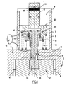
- the device comprises a rupturable pin 1 mounted at the level of the structural fastener of a screw jack system, so as to come across a room linked to the secondary road and another room linked to an organ attached to the primary road.
- the pin 1 is substantially cylindrical and extends longitudinally along its main axis 14.
- journal 2 of the secondary nut (not shown).
- a support 3 Said other part connected to an integral member of the primary track is here a support 3, a lower portion is secured to a transfer plate 5 ensuring the proper connection of the primary nut.
- Said transfer plate 5 surrounds with a small clearance (illustrated by the arrows 4) the pin 2 of the secondary nut.
- the journal 2 has on one external face a reservation into which one of the ends (lower end 10) of the pin 1, the reservation whose peripheral edge is covered by the lower part of said support 3 secured to the transfer plate 5.
- the pin 1 thus has a contact zone with the lower part of said support 3, this zone of the pin 1 advantageously having a section to be broken 6 that can be sheared during a relative movement between the support 3 and the pin 1.
- the lower end 10 of the pin 1 has a section whose diameter is greater than that of the section of the portion of the pin passing through the support 3, so that said lower end of the pin can be retained in the pin 2 by abutting on the support 3.
- the support 3 also extends along the main axis 14 of the pin so as to form a cylindrical tube surrounding the detection device according to the invention.
- Said tube advantageously comprises a cover 9, in particular making it possible to maintain the mounting of the device according to the invention, as well as its protection vis-à-vis the external environment.
- the pin 1 has, at its end opposite to that penetrating the reservation of the pin 2, a circumferential protrusion (upper plate 7) that can be pushed from the lower part of the support 3, along the axis 14, by a first member of elastic return disposed between said upper plate 7 and the upper part of the support 3.
- said first elastic return member is a helical spring 8 surrounding the pin.
- a transfer of the load on the secondary path is accompanied by a relative movement (authorized by the game which has been reported) between the transfer plate 5 and the journal 2.
- the portion of the pin having the upper plate 7 is then spaced from the portion of the pin remaining in the pin 2 (lower end 10) in a translation movement along the axis 14.
- the pin 1 comprises, at the level of the zone which is surrounded by the support 3, a guide 11 making it possible to prevent "Burrs" due to the breaking of the pawn can come block the separation of the pawn in two parts.
- the detection device further comprises a lower plate 12 surrounding the pin 1, being interposed between the upper plate 7 of said pin 1 and the lower part of the support 3.
- the upper plate 7 and lower 12 and have faces facing one another.
- the lower plate 12 is connected to the lower part of the support 3 by a second elastic return member 13 adapted to bring the lower plate 12 to the upper plate 7, so that elements 14, 15 respectively connected to said upper plates 7 and lower 12 are in contact during normal operation of the jack system (when the primary channel is loaded).
- said elements 14, 15 connected to the trays 7, 12 may be spaced from each other by a predefined distance.
- said second elastic return member is a helical spring 13 surrounding the pin.
- the detection device comprises means for detecting the rupture of the pin 1 able to determine that said plates 12, 13 are separated (or at least a distance greater than the predefined distance separating them in normal operating mode).
- the rupture detection means may comprise at least one pair of sensors, each of the sensors 14, 15 of a pair being disposed on one respectively of the plates 7, 12 so as to be two by two opposite .
- the means for detecting the rupture also comprise means (for example in the form of a monitoring device 16) able to determine whether the spacing of the sensors is normal or irregular.
- induction Hall effect sensors LVDT Linear Variable-Differential Transformer for Linear Variation Differential Transformer.
- the sensors 14, 15 are electrical contacts each connected by an electrical connection to the monitoring device 16.
- Said sensors thus provide electrical continuity when the plates are in contact with each other.
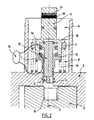
- the detection device also comprises means for verifying, without breaking the pin, the operation of said means for detecting the rupture.
- these verification means comprise a substantially cylindrical push button 17, guided along the axis 14, using the cover 9.
- One of the ends (upper end) of said knob 17 advantageously exceeds the cover 9 while the other end has a stop plate 18 disposed above the upper plate 7.
- Said stop plate 18 extends in the form of fingers 19 passing through openings made for this purpose in the upper plate 7 and coming into contact with the face of the lower plate 12 which is opposite the upper plate 7.
- the application of a force (for example by an operator) on the upper end of the push button 17 thus makes it possible to press the fingers 19 on the surface of the lower plate 12, by putting the second spring 13 under tension.
- the lower plate 12 can thus be pushed towards the lower part of the support 3, so that the plates 7, 12 are spaced from each other (see Figure 3).
- the sensors 14, 15 are then moved away from one another and the monitoring device 16 will then detect this abnormal gap.
- the device according to the invention makes it possible in particular to ensure that the sensors and the monitoring device function properly or that the parts are not seized.
- the verifiability of the device according to the invention makes it possible to increase the level of safety, thus decreasing the risk that a charge transfer on the secondary channel is not immediately detected.
- the button 17 has visual markers 20, 21 (for example strips of different colors) making it possible in particular to confirm a failure by a visual detection at the examination of said button 17.
- the button 17 is pushed back when the upper plate 7 abuts against the stop plate 18, causing this ci in its race, so that the two marks 21, 20 are then visible. The failure can then be visually detected.
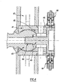
- Such an aircraft fastener is generally provided via a primary fastening bar with the structure of the aircraft.
- the screw (not shown) of the cylinder system is thus rotatably connected with a sphere 40 of the tie bar.
- the sphere 40 rotates freely in a ball joint constituted by two half-ball joints (respectively a left half-ball 41 and half-right knee 42) integral with the secondary path.
- One of the ends of a shear cylinder 45 enters the sphere 40, said cylinder being consequently connected to a part integral with the primary track.
- a rolling member 44 is disposed at the area of contact between the sphere 40 and the cylinder 45 to neutralize the rotation of the sphere in the ball. In this way, the cylinder 45 has no relative movement vis-à-vis the elements related to the secondary path.
- the other end of the cylinder 45 comprises arms adapted to each accommodate the lower end of the pin of a detection device 50 according to the invention.
- At least one verifiable device is disposed at the level of the aircraft fastener so that its ruptible pin passes through a support 46, integral with the right half-ball 42 and therefore of the secondary track, and one of the arms said cylinder 45.
- two devices 50 according to the first aspect of the invention are used for the detection of a possible failure of the primary channel.
- the detection device is not solicited.
- the first spring will then move the upper plate of the lower plate, which will cause the detection of the transfer of load on the secondary track at the level of this aircraft attachment.
- the invention also relates to the actuator cylinders of movable member comprising a detection device such as that described in the previous description, at its aircraft attachment and its fastener structure.
Landscapes
- Engineering & Computer Science (AREA)
- Mechanical Engineering (AREA)
- General Engineering & Computer Science (AREA)
- Automation & Control Theory (AREA)
- Aviation & Aerospace Engineering (AREA)
- Testing Of Devices, Machine Parts, Or Other Structures Thereof (AREA)
- Transmission Devices (AREA)
- Geophysics And Detection Of Objects (AREA)
- Control Of Transmission Device (AREA)
- Looms (AREA)
- Investigating Strength Of Materials By Application Of Mechanical Stress (AREA)
Claims (25)
- Vorrichtung zur Erfassung des Lastüberganges einer Schraubenspindel eines Betätigungsgliedes eines beweglichen Organs von einem Primärweg zu einem Sekundärweg, wobei der Sekundärweg dazu eingerichtet ist, die Last der Spindel im Falle des Ausfalls des Primärwegs zu übernehmen, wobei die genannte Vorrichtung einen Abreißstift (1) umfaßt, der ein erstes Teil (2), das mit dem Sekundärweg verbunden ist, und ein zweites Teil (3) durchsetzt, das mit einem Organ (5) verbunden ist, das fest mit dem Primärweg verbunden ist, so daß ein Übergang der Last zum Sekundärweg sich in eine Scherung zwischen den genannten Teilen (2, 3) übersetzt, die vom Stift (1) durchsetzt sind, die das Abreißen des genannten Stiftes (1) hervorruft, und wobei die genannte Vorrichtung dadurch gekennzeichnet ist, daß sie umfaßt:• Mittel (14, 15, 16) zum Erfassen des Abreißen des Stiftes, was gestattet, einen Ausfall des Primärweges zu bestimmen, und• Mittel zur Bestätigung der Funktion der genannten Mittel zum Erfassen, ohne Abreißen des Stiftes (1), derart, daß man sich vom guten Zustand des Stiftes überzeugt.
- Vorrichtung nach Anspruch 1, dadurch gekennzeichnet, daß der Abreißstift (1) ein oberes Plateau (7) umfaßt, und daß ein erstes, elastisches Rückstellorgan (8), das sich einerseits auf dem genannten oberen Plateau (7) und andererseits auf dem genannten zweiten Teil (3) abstützt, das mit einem fest mit dem Primärweg verbunden Organ verbunden ist, über dem Stift (1) eine Spreizkraft erzeugt, so daß das Abreißen des Stiftes (1) eine Spreizung der beiden Teile des Stiftes (1) hervorruft, die durch das Abreißen getrennt werden.
- Vorrichtung nach Anspruch 2, dadurch gekennzeichnet, daß sie außerdem umfasst:• ein unteres Plateau (12), das den Stift (1) umgibt und zwischen dem genannten oberen Plateau (7) und dem genannten zweiten Teil (3) angeordnet ist, und• ein zweites, elastisches Rückstellorgan (13), das sich auf dem genannten unteren Plateau (12) und dem genannten zweiten Teil (3) abstützt, so daß das genannte obere (7) und untere Plateau (12) voreinander entfernt werden können, wenn- im Falle des Abreißens des Stiftes (1) unter der Wirkung des genannten ersten Rückstellorgans (8) der Teil des Stiftes (1), der das obere Plateau (7) umfaßt, vom genannten zweiten Teil (3) entfernt wird, und- im Falle der Aufbringung einer Kraft auf das untere Plateau (12), die das genannten zweite Rückstellorgan (13) unter Spannung setzt, das untere Plateau (12) an das genannte zweite Teil (3) angenähert wird.
- Vorrichtung nach Anspruch 3, dadurch gekennzeichnet, daß die genannten Erfassungsmittel umfassen:• Meßfühler, wobei jeder der Meßfühler (14, 15) eines Meßfühlerpaares auf einem des genannten unteren (12) und oberen Plateaus (7) derart angeordnet sind, daß die genannten Meßfühler (14, 15) nebeneinander sind; und• Mittel (16), die geeignet sind, es zu bestimmen, ob die Entfernung der Meßfühler regulär ist oder nicht.
- Vorrichtung nach Anspruch 4, dadurch gekennzeichnet, daß die Entfernung zwischen den Meßfühlern als nicht regulär angesehen wird, sobald die Entfernung zwischen den Meßfühlern (14, 15) infolge der Tatsache des Abreißen des Stiftes (1) oder der Aufbringung einer ausreichenden Kraft auf das untere Plateau (12) zugenommen hat.
- Vorrichtung nach einem der Ansprüche 4 oder 5, dadurch gekennzeichnet, daß die reguläre Entfernung der Meßfühler die einer Entfernung Null ist, wobei die genannten Meßfühler (14, 15) nur durch einen Bruch des Stiftes (1) oder die Aufbringung einer ausreichenden Kraft auf das untere Plateau (12) auseinandergebracht werden.
- Vorrichtung nach Anspruch 6, dadurch gekennzeichnet, daß die Meßfühler elektrische Kontakte (14, 15) sind, und daß die genannten Mittel (16), die geeignet sind, zu bestimmen, ob die Entfernung zwischen den Meßfühlern regulär ist oder nicht, Mittel zum Erfassen der Unterbrechung einer elektrischen Verbindung sind.
- Vorrichtung nach einem der Ansprüche 4 bis 7, dadurch gekennzeichnet, daß die genannten Mittel zur Bestätigung der Erfassungsmittel Mittel umfassen, die es gestatten, die Meßfühler (14, 15) voneinander zu entfernen, um sich auf diese Weise zu vergewissern, daß die genannten Mittel zur Erfassung eine nicht reguläre Entfernung der Meßfühler gut identifizieren.
- Vorrichtung nach Anspruch 8, dadurch gekennzeichnet, daß die genannten Mittel, die es gestatten, die Meßfühler (14, 15) voneinander zu entfernen, einen Druckknopf (17) umfassen, der betätigt werden kann, um derart auf das untere Plateau (12) zu drücken, daß das untere Plateau (12) vom oberen Plateau (7) entfernt wird, indem man das zweite Rückstellorgan (13) unter Spannung setzt.
- Vorrichtung nach Anspruch 9, dadurch gekennzeichnet, daß der Druckknopf (17) ein Halteplateau (18) umfaßt, gegen das das obere Plateau (7) infolge des Abreißens des Zapfens (1) stößt.
- Vorrichtung nach Anspruch 10, dadurch gekennzeichnet, daß der Druckknopf (17) sichtbare Markierungen (20, 21) umfaßt, die eine optische Erfassung einer normalen Funktion oder eines Ausfalls des Primärweges gestatten.
- Vorrichtung nach einem der Ansprüche 3 bis 11, dadurch gekennzeichnet, daß das genannte erste und zweite elastische Rückstellorgan wendelförmige Federn (8, 13) sind, die den Stift (1) umgeben, und daß das genannte erste Rückstellorgan (8) das genannte zweite Rückstellorgan (13) umgibt.
- Stellglied zur Betätigung eines beweglichen Organs, umfassend:• eine Schraubenspindel und eine Anbringungsstruktur, durch welche die Schraubenspindel mit dem beweglichen Organ verbunden ist, wobei die genannte Anbringungsstruktur dadurch verdoppelt ist, daß sie einen Primärweg und einen Sekundärweg zur Betätigung des genannten Organs umfaßt, wobei der genannte Sekundärweg dazu vorgesehen ist, einen Ausfall des Primärwegs zu ersetzen, wobei zwei Muttern, von denen eine eine Primärmutter und eine eine Sekundärmutter ist, hierzu rund um die Schraubenspindel in Eingriff stehen und jeweils mit dem beweglichen Organ über eine eigene Verbindung verbunden sind, und wobei die Sekundärmutter dazu ausgebildet ist, die Last der Schraubenspindel im Falle des Ausfalls der Primärmutter zu übernehmen, und• einen abreißbaren Stift (1), der einen Lagerzapfen (2) der Sekundärmutter und einen unteren Teil eines Supports (3) durchsetzt, der mit einer Übertragungsplatte (5) verbunden ist, die fest mit der eigentlichen Verbindung der Primärmutter mit dem beweglichen Organ verbunden ist, so daß ein Lastübergang auf den zweiten Weg sich in eine Scherung zwischen dem Lagerzapfen (2) und dem genannten Support (3) übersetzt, die das Abreißen des genannten Stiftes (1) hervorruft,wobei das genannte Stellglied dadurch gekennzeichnet ist, daß es Mittel (14, 15, 16) zur Erfassung des Abreißen des Stiftes (1), die es gestatten, einen Ausfall des Primärweges zu bestimmen, und Mittel zur Bestätigung der Funktion der genannten Erfassungsmittel ohne Abreißen des Stiftes umfaßt, um sich auf diese Weise vom guten Funktionszustand des Stiftes (1) zu versichern.
- Stellglied nach Anspruch 13, dadurch gekennzeichnet, daß der Lagerzapfen (2) eine Ausnehmung darbietet, in die das eine der Enden des Stiftes (1) eindringt, wobei der Umfangsrand der genannten Ausnehmung vom genannten unteren Teil des Supports (3) abgedeckt wird, der fest mit der Übertragungsplatte (5) verbunden ist.
- Stellglied nach Anspruch 14, dadurch gekennzeichnet, daß der abreißbare Stift (1) ein oberes Plateau (7) an dem seiner Enden umfaßt, das nicht in den Lagerzapfen (2) eindringt, und daß ein erstes, elastisches Rückstellorgan (8), das sich einerseits auf dem genannten, obere Plateau (7) und andererseits auf dem genannten, unteren Teil des Supports (3) abstützt, auf dem Stift (1) eine Trennkraft erzeugt, so daß das Abreißen des Stiftes (1) ein Auseinanderbewegen der beiden Teile des Stiftes (1) hervorruft, die durch das Abreißen getrennt wurden.
- Stellglied nach Anspruch 15, dadurch gekennzeichnet, daß es außerdem umfaßt:• ein untere Plateau (12), das den Stift (1) umgibt und zwischen dem genannten oberen Plateau (7) und dem genannten unteren Teil des Supports (3) angeordnet ist, und• ein zweites elastisches Rückstellorgan (13), das sich auf dem genannten unteren Plateau (12) und dem genannten unteren Teil des Supports (3) derart abstützt, daß das genannte obere (7) und untere Plateau (12) voneinander entfernt werden können, wenn:- im Falle des Abreißens des Stiftes (1) unter Wirkung des genannten, ersten Rückstellorgans (8) der Teil des Stiftes (1), der das obere Plateau (7) umfaßt, vom genannten unteren Teil des Supports (3) entfernt wird, und- im Fall der Aufbringung einer Kraft auf das untere Plateau (12), das das genannte zweite Rückstellorgan (13) unter Spannung setzt, das untere Plateau (12) an den genannten, unteren Teil des Supports (3) angenähert wird.
- Stellglied zur Betätigung eines beweglichen Organs eines Luftfahrzeugs, umfassend:• eine Schraubenspindel und eine flugzeugseitige Anbringung, mit der die Schraubenspindel mit einem Luftfahrzeug verbunden ist, wobei die genannte flugzeugseitige Anbringung dahingehend verdoppelt ist, daß sie einen Primärweg und einen Sekundärweg der Anbringung an den Aufbau des Luftfahrzeugs umfaßt, wobei der genannte Sekundärweg dazu vorgesehen ist, bei einem Ausfall des Primärwegs einen Ersatz zu bieten, die Schraubenspindel hierzu mit einer Kugel (40) einer Primär-Anbringungsstange am Flugzeug drehbar verbunden ist, sich die genannte Kugel frei in einem Kugelgelenk (41, 42) dreht, das fest mit einer Sekundäranbringung (43) an das Luftfahrzeug verbunden ist, wobei das genannte Kugelgelenk angeordnet ist, um die Last im Fall eines Ausfalls des Primärwegs zu übernehmen, und die genannte Kugel (40) dann in Berührung mit dem genannten Kugelgelenk (41, 42) gelangt, und• einen abreißbaren Stift (1), der ein mit dem Kniegelenk verbundenes Teil (46) und ein mit der Kugel fest verbundenes Teil (45) durchsetzt, so daß dann, wenn ein Ladungsübergang nach dem Sekundärweg durch Scherung zwischen dem mit dem Kniegelenk verbundenen Teil und dem genannten, mit der Kugel fest verbundenen Teil erfolgt, das Abreißen des Stiftes hervorgerufen wird,wobei der Stellantrieb dadurch gekennzeichnet ist, daß er Mittel zum Erfassen des Bruchs des Stiftes (1) umfaßt, die es gestatten, einen Ausfall des Primärweges zu bestimmen, und Mittel zur Bestätigung, über der Funktion der genannten Erfassungsmittel ohne Abreißen des Stiftes, so daß man sich vom guten Funktionszustand des Stiftes (1) überzeugen kann.
- Stellglied nach Anspruch 17, dadurch gekennzeichnet, daß das genannte, mit der Kugel fest verbundene Teil ein Scherzylinder (45) ist:• bei dem das eine der Enden in die Kugel (40) eindringt, wobei ein rollendes Element (44) zwischen der Kugel und dem Zylinder derart eingeschoben ist, daß die Kugel ihre Drehbewegung nicht auf den Zylinder überträgt, und• dessen anderes Ende Arme aufweist, die geeignet sind, jeweils das untere Ende des Stiftes (1) aufzunehmen.
- Stellglied nach Anspruch 18, dadurch gekennzeichnet, daß der abreißbare Stift (1) ein oberes Plateau (7) an dem seiner Enden umfaßt, das nicht in einen der Arme des genannten Scherzylinders (45) eindringt, und daß ein erstes elastisches Rückstellorgan (8), das sich einerseits auf dem genannten oberen Plateau (7) und andererseits auf dem genannten Teil (46) abstützt, das mit dem Kugelgelenk verbunden ist, eine Trennkraft auf den Stift (1) ausübt, so daß das Abreißen des Stiftes (1) eine Auseinanderbewegung der beiden Teile des Stiftes (1) hervorruft, die durch das Abreißen getrennt wurden.
- Stellglied nach Anspruch 19, dadurch gekennzeichnet, daß es außerdem umfaßt:• ein unteres Plateau (12), das den Stift (1) umgibt und zwischen dem genannten oberen Plateau (7) und dem genannten Teil (46) angeordnet ist, das mit dem Kugelgelenk verbunden ist, und• ein zweites elastisches Rückstellorgan (13), das sich auf dem genannten unteren Plateau (12) und dem genannten Teil (46) abstützt, das mit dem Kugelgelenk verbunden ist, so daß das genannte obere (7) und untere Teil (12) sich auseinanderbewegen können, wenn- im Fall des Abreißens des Stiftes (1) unter der Wirkung des genannten ersten Rückstellorgans (8) der Teil des Stiftes (1), der das obere Plateau (7) umfaßt, vom genannten Teil (46), das mit dem Kugelgelenk verbunden ist, entfernt wird, und- im Fall der Aufbringung einer Kraft auf das untere Plateau (12), die das genannte zweite Rückstellorgan (13) unter Spannung setzt, das genannte untere Plateau (12) an das genannte Teil (46), das mit dem Kugelgelenk verbunden ist, angenähert wird.
- Stellglied nach einem der Ansprüche 16 oder 20, dadurch gekennzeichnet, daß die genannten Erfassungsmittel umfassen:• mindestens ein Paar elektrischer Kontakte, wobei jeder der genannten Kontakte (14, 15) eines Paares auf der einen beziehungsweise dem genannten unteren (12) und oberen (7) Plateau derart angebracht ist bzw. sind, daß die genannten Kontakte (14, 15), die paarweise in Kontakt stehen, so eine elektrische Verbindung sicherstellen, und• Mittel (16), die dazu geeignet sind, zu bestimmen, ob die Meßfühler in Kontakt stehen oder nicht, und zwar durch Erfassen des Abreißens der genannten elektrischen Verbindung.
- Stellglied nach dem vorhergehenden Anspruch, dadurch gekennzeichnet, daß die genannten Bestätigungsmittel der Erfassungsmittel Mittel umfassen, die es gestatten, die Meßfühler (14, 15) so auseinanderzubewegen, daß man bestätigt erhält, daß die Erfassungsmittel gut ein Abreißen der elektrischen Verbindung identifizieren.
- Stellglied nach einem der Ansprüche 16 oder 20, in dem, nachfolgend an das Abreißen des Stiftes (1), der Teil des Stiftes, der das Plateau (7) enthält, unter der Wirkung des genannten ersten Organs (8) versetzt wird, dadurch gekennzeichnet, daß die genannten Erfassungsmittel von Meßfühlern gebildet werden, die befähigt sind, eine Translation zu erkennen, besonders von Meßfühlern unter der Gruppe, die gebildet ist von den LVDT-Meßfühlern, den induktiven Meßfühlern und den Halleffekt-Meßfülern.
- Stellglied nach dem vorhergehenden Anspruch, dadurch gekennzeichnet, daß die genannten Bestätigungsmittel der Erfassungsmittel Mittel umfassen, die es gestatten, die Meßfühler (14, 15) auseinanderzubewegen, um auf diese Weise zu bestätigen, daß die genannten Erfassungsmittel eine Translation eines Teils des Stiftes (1) gut identifizieren.
- Stellglied nach einem der Ansprüche 22 oder 24, dadurch gekennzeichnet, daß die genannten Mittel, die es gestatten, die Meßfühler (14, 15) auseinanderzubewegen, einen Druckknopf (17) umfassen, der betätigt werden kann, um auf das untere Plateau (12) zu drücken, so daß das untere Plateau (12) vom oberen Plateau (7) entfernt wird, indem man das zweite Rückstellorgan (13) unter Spannung setzt.
Applications Claiming Priority (2)
| Application Number | Priority Date | Filing Date | Title |
|---|---|---|---|
| FR0400539A FR2865254B1 (fr) | 2004-01-21 | 2004-01-21 | Dispositif de detection de transfert de charge par cisaillement d'un pion ruptible |
| FR0400539 | 2004-01-21 |
Publications (2)
| Publication Number | Publication Date |
|---|---|
| EP1557588A1 EP1557588A1 (de) | 2005-07-27 |
| EP1557588B1 true EP1557588B1 (de) | 2007-07-04 |
Family
ID=34630657
Family Applications (1)
| Application Number | Title | Priority Date | Filing Date |
|---|---|---|---|
| EP05290104A Expired - Lifetime EP1557588B1 (de) | 2004-01-21 | 2005-01-18 | Detektionvorrichtung zur Lastübertragung mit einem Scherstift |
Country Status (4)
| Country | Link |
|---|---|
| EP (1) | EP1557588B1 (de) |
| DE (1) | DE602005001511T2 (de) |
| ES (1) | ES2287879T3 (de) |
| FR (1) | FR2865254B1 (de) |
Cited By (1)
| Publication number | Priority date | Publication date | Assignee | Title |
|---|---|---|---|---|
| EP3854693B1 (de) * | 2016-07-27 | 2023-12-20 | Ratier-Figeac SAS | Aktuatoranordnung und verfahren zum reagieren auf ein drehmoment auf demselben |
Families Citing this family (12)
| Publication number | Priority date | Publication date | Assignee | Title |
|---|---|---|---|---|
| FR2912374B1 (fr) * | 2007-02-08 | 2009-05-08 | Goodrich Actuation Systems Sas | Detection de la reprise d'effort par une voie secondaire d'un actionneur de commande de vol |
| FR2913949B1 (fr) | 2007-03-23 | 2009-10-02 | Goodrich Actuation Systems Sas | Perfectionnements a la detection de la reprise d'effort de la voie secondaire d'un actionneur de commande de vol. |
| DE102009040344B4 (de) * | 2009-09-08 | 2016-03-24 | Deutsches Zentrum für Luft- und Raumfahrt e.V. | Aktuator mit integriertem Zustandsüberwachungssystem sowie Verfahren zur Zustandsüberwachung sowie Verfahren zur Herstellung eines Aktuators |
| FR2959482B1 (fr) | 2010-04-30 | 2012-05-25 | Goodrich Actuation Systems Sas | Dispositif de detection de la rupture d'une voie primaire dans un actionneur de commande de vol |
| DE102011018446B4 (de) | 2011-04-21 | 2023-01-26 | Liebherr-Aerospace Lindenberg Gmbh | Stellvorrichtung, insbesondere Stellvorrichtung für ein Luftfahrzeug |
| CA2919342C (en) | 2015-04-15 | 2023-08-15 | Goodrich Actuation Systems Sas | Check device for flight actuator primary load path failure detection device |
| CN106143876B (zh) * | 2015-04-24 | 2023-11-24 | 空客(北京)工程技术中心有限公司 | 顶推装置、活动机构和飞行器 |
| EP3404395B1 (de) | 2017-05-19 | 2020-01-29 | Goodrich Actuation Systems SAS | Testverfahren und testvorrichtung für flugstellglied-prüfvorrichtung |
| US11707010B2 (en) | 2019-06-14 | 2023-07-25 | Cnh Industrial America Llc | System and method for monitoring the operational status of tools of an agricultural implement |
| US11015993B2 (en) | 2019-10-02 | 2021-05-25 | Cnh Industrial America Llc | System and method for wirelessly monitoring the operational status of tools of an agricultural implement |
| US11506723B2 (en) | 2019-10-02 | 2022-11-22 | Cnh Industrial America Llc | System and method for monitoring the operational status of tools of an agricultural implement utilizing connectivity |
| US12150397B2 (en) | 2021-03-19 | 2024-11-26 | Cnh Industrial America Llc | System and method for monitoring an operational status of a shear pin for a ground-engaging assembly of an agricultural implement |
Family Cites Families (6)
| Publication number | Priority date | Publication date | Assignee | Title |
|---|---|---|---|---|
| US4273006A (en) * | 1978-09-27 | 1981-06-16 | Mcdonnell Douglas Corporation | Aircraft horizontal stabilizer drive |
| GB0112984D0 (en) * | 2001-05-30 | 2001-07-18 | Lucas Industries Ltd | Screw actuator |
| EP1283384A3 (de) * | 2001-08-09 | 2004-08-11 | Smiths Wolverhampton Limited | Sicherungsmutter für eine Kugelumlaufspindel |
| FR2830916B1 (fr) * | 2001-10-12 | 2004-08-13 | Ratier Figeac Soc | Systeme vis-ecrou a recirculation d'organes roulants, notamment a billes, et a ensemble d'ecrou et de contre-ecrou de securite |
| FR2844325B1 (fr) | 2002-09-11 | 2004-11-19 | Trw Sys Aeronautiques Civil | Detection par pion electrifie de transfert de charge sur ecrou secondaire dans un verin a vis |
| FR2844326B1 (fr) * | 2002-09-11 | 2005-05-13 | Trw Sys Aeronautiques Civil | Verin a vis a moyen de blocage en cas de passage sur ecrou secondaire |
-
2004
- 2004-01-21 FR FR0400539A patent/FR2865254B1/fr not_active Expired - Fee Related
-
2005
- 2005-01-18 EP EP05290104A patent/EP1557588B1/de not_active Expired - Lifetime
- 2005-01-18 DE DE602005001511T patent/DE602005001511T2/de not_active Expired - Lifetime
- 2005-01-18 ES ES05290104T patent/ES2287879T3/es not_active Expired - Lifetime
Non-Patent Citations (1)
| Title |
|---|
| None * |
Cited By (1)
| Publication number | Priority date | Publication date | Assignee | Title |
|---|---|---|---|---|
| EP3854693B1 (de) * | 2016-07-27 | 2023-12-20 | Ratier-Figeac SAS | Aktuatoranordnung und verfahren zum reagieren auf ein drehmoment auf demselben |
Also Published As
| Publication number | Publication date |
|---|---|
| FR2865254B1 (fr) | 2007-05-11 |
| ES2287879T3 (es) | 2007-12-16 |
| EP1557588A1 (de) | 2005-07-27 |
| DE602005001511T2 (de) | 2008-03-06 |
| DE602005001511D1 (de) | 2007-08-16 |
| FR2865254A1 (fr) | 2005-07-22 |
Similar Documents
| Publication | Publication Date | Title |
|---|---|---|
| EP1557588B1 (de) | Detektionvorrichtung zur Lastübertragung mit einem Scherstift | |
| EP1398542B1 (de) | Funktionsversagensermittlung an Schraubenspindel betätigen, durch Bruch von mit Leiterdraht versehenen Scherstiften | |
| EP1972549B1 (de) | Perfektionierungen der Erfassung des Drucks auf ein Stellglied zur Flugsteuerung | |
| EP1958871B1 (de) | Erfassung der Wiederherstellung des Drucks über eine Nebenleitung eines Stellglieds zur Flugsteuerung | |
| EP2022696B1 (de) | Vorrichtung zur Führung einer Seilbahn einer mechanischen Aufstiegsanlage mit automatischen Haltemitteln für die Anlage | |
| EP2459427B1 (de) | Verfahren und vorrichtung zur erkennung des entgleisens eines fahrerlosen fahrzeuges | |
| EP2832622B1 (de) | Methode und Vorrichtungen zur Kontrolle der korrekten Aufgleisung eines spurgeführten Fahrzeugs | |
| EP2654105B1 (de) | Verfahren und System zum Erfassen der Öffnung eines Dichtelements für einen abgedichteten Akkumulator | |
| EP2332838A1 (de) | Testvorrichtung zur Erfassung der Wiederherstellung des Drucks über eine Nebenleitung eines Stellglieds zur Flugsteuerung, und entsprechendes Testverfahren | |
| EP1340958B1 (de) | Vorrichtung zur Messung der Abnutzung einer Schraube in einer Mutter- und Schraubenanordnung | |
| EP0194179B1 (de) | Selbsteinstellbarer Bowdenzug mit elektrischem Taster zur Funktionsanzeige | |
| EP2876008B1 (de) | Elektromechanisches Stellglied für Fahrzeugbremse und Bremssystem, das ein solches Stellglied umfasst. | |
| EP1398541B1 (de) | Spindelantrieb mit klemmender Vorrichtung beim belasten der zweiten Mutter | |
| FR3093704A1 (fr) | Attache moteur arrière d’un ensemble propulsif d’aéronef | |
| FR2462797A1 (fr) | Dispositif d'immobilisation d'un connecteur femelle dans un connecteur male pour une liaison electrique coaxiale | |
| FR2858035A1 (fr) | Systeme de controle d'une barre de securite d'un verin a vis | |
| EP2397435B1 (de) | Verbindungsvorrichtung zur Sicherstellung der Verbindung zwischen einem Hebezeug und einem Werkstück | |
| FR2916023A1 (fr) | Liaison mecanique fusible entre deux ecrous sur un ensemble a vis de securite a defaillance. | |
| FR2975076A1 (fr) | Dispositif de reglage, en particulier dispositif de reglage pour un aeronef | |
| FR2865187A1 (fr) | Dispositif de detection de transfert de charge par variation de temperature | |
| EP1270980B1 (de) | Scheibenbremse, insbesondere für Industriegebrauch | |
| FR2962855A1 (fr) | Dispositif de signalisation d'un deblocage par rapport a un element | |
| CA3161217A1 (fr) | Porte d'aeronef a verrou de blocage de securite comportant une biellette a polymere electroactif | |
| FR2975154A1 (fr) | Dispositif de reglage de tige filetee avec cheminement double de charge | |
| FR3066561A1 (fr) | Ferrure formant fusible pour un systeme d'entrainement en translation d'un verin |
Legal Events
| Date | Code | Title | Description |
|---|---|---|---|
| PUAI | Public reference made under article 153(3) epc to a published international application that has entered the european phase |
Free format text: ORIGINAL CODE: 0009012 |
|
| AK | Designated contracting states |
Kind code of ref document: A1 Designated state(s): AT BE BG CH CY CZ DE DK EE ES FI FR GB GR HU IE IS IT LI LT LU MC NL PL PT RO SE SI SK TR |
|
| AX | Request for extension of the european patent |
Extension state: AL BA HR LV MK YU |
|
| 17P | Request for examination filed |
Effective date: 20050822 |
|
| AKX | Designation fees paid |
Designated state(s): DE ES FR GB IT |
|
| GRAP | Despatch of communication of intention to grant a patent |
Free format text: ORIGINAL CODE: EPIDOSNIGR1 |
|
| GRAS | Grant fee paid |
Free format text: ORIGINAL CODE: EPIDOSNIGR3 |
|
| GRAA | (expected) grant |
Free format text: ORIGINAL CODE: 0009210 |
|
| AK | Designated contracting states |
Kind code of ref document: B1 Designated state(s): DE ES FR GB IT |
|
| REG | Reference to a national code |
Ref country code: GB Ref legal event code: FG4D Free format text: NOT ENGLISH |
|
| REF | Corresponds to: |
Ref document number: 602005001511 Country of ref document: DE Date of ref document: 20070816 Kind code of ref document: P |
|
| GBT | Gb: translation of ep patent filed (gb section 77(6)(a)/1977) |
Effective date: 20070914 |
|
| REG | Reference to a national code |
Ref country code: ES Ref legal event code: FG2A Ref document number: 2287879 Country of ref document: ES Kind code of ref document: T3 |
|
| PLBE | No opposition filed within time limit |
Free format text: ORIGINAL CODE: 0009261 |
|
| STAA | Information on the status of an ep patent application or granted ep patent |
Free format text: STATUS: NO OPPOSITION FILED WITHIN TIME LIMIT |
|
| 26N | No opposition filed |
Effective date: 20080407 |
|
| REG | Reference to a national code |
Ref country code: FR Ref legal event code: PLFP Year of fee payment: 12 |
|
| REG | Reference to a national code |
Ref country code: FR Ref legal event code: PLFP Year of fee payment: 13 |
|
| REG | Reference to a national code |
Ref country code: FR Ref legal event code: PLFP Year of fee payment: 14 |
|
| PGFP | Annual fee paid to national office [announced via postgrant information from national office to epo] |
Ref country code: FR Payment date: 20211215 Year of fee payment: 18 Ref country code: GB Payment date: 20211216 Year of fee payment: 18 |
|
| PGFP | Annual fee paid to national office [announced via postgrant information from national office to epo] |
Ref country code: DE Payment date: 20211215 Year of fee payment: 18 |
|
| PGFP | Annual fee paid to national office [announced via postgrant information from national office to epo] |
Ref country code: IT Payment date: 20220103 Year of fee payment: 18 Ref country code: ES Payment date: 20220201 Year of fee payment: 18 |
|
| REG | Reference to a national code |
Ref country code: DE Ref legal event code: R119 Ref document number: 602005001511 Country of ref document: DE |
|
| GBPC | Gb: european patent ceased through non-payment of renewal fee |
Effective date: 20230118 |
|
| PG25 | Lapsed in a contracting state [announced via postgrant information from national office to epo] |
Ref country code: GB Free format text: LAPSE BECAUSE OF NON-PAYMENT OF DUE FEES Effective date: 20230118 Ref country code: DE Free format text: LAPSE BECAUSE OF NON-PAYMENT OF DUE FEES Effective date: 20230801 |
|
| PG25 | Lapsed in a contracting state [announced via postgrant information from national office to epo] |
Ref country code: FR Free format text: LAPSE BECAUSE OF NON-PAYMENT OF DUE FEES Effective date: 20230131 |
|
| PG25 | Lapsed in a contracting state [announced via postgrant information from national office to epo] |
Ref country code: IT Free format text: LAPSE BECAUSE OF NON-PAYMENT OF DUE FEES Effective date: 20230118 |
|
| REG | Reference to a national code |
Ref country code: ES Ref legal event code: FD2A Effective date: 20240327 |
|
| PG25 | Lapsed in a contracting state [announced via postgrant information from national office to epo] |
Ref country code: ES Free format text: LAPSE BECAUSE OF NON-PAYMENT OF DUE FEES Effective date: 20230119 |
|
| PG25 | Lapsed in a contracting state [announced via postgrant information from national office to epo] |
Ref country code: ES Free format text: LAPSE BECAUSE OF NON-PAYMENT OF DUE FEES Effective date: 20230119 |