EP1557597B1 - Druckregelventil für einen Hochdruckspeicher einer Verbrennungskraftmaschine - Google Patents
Druckregelventil für einen Hochdruckspeicher einer Verbrennungskraftmaschine Download PDFInfo
- Publication number
- EP1557597B1 EP1557597B1 EP04028091A EP04028091A EP1557597B1 EP 1557597 B1 EP1557597 B1 EP 1557597B1 EP 04028091 A EP04028091 A EP 04028091A EP 04028091 A EP04028091 A EP 04028091A EP 1557597 B1 EP1557597 B1 EP 1557597B1
- Authority
- EP
- European Patent Office
- Prior art keywords
- valve
- pressure
- spring
- control valve
- pressure control
- Prior art date
- Legal status (The legal status is an assumption and is not a legal conclusion. Google has not performed a legal analysis and makes no representation as to the accuracy of the status listed.)
- Expired - Lifetime
Links
- 238000002485 combustion reaction Methods 0.000 title claims description 12
- 238000007789 sealing Methods 0.000 claims description 11
- 239000000446 fuel Substances 0.000 description 17
- 230000001105 regulatory effect Effects 0.000 description 16
- 230000006835 compression Effects 0.000 description 8
- 238000007906 compression Methods 0.000 description 8
- 125000006850 spacer group Chemical group 0.000 description 4
- 238000005553 drilling Methods 0.000 description 2
- 239000002828 fuel tank Substances 0.000 description 2
- 238000002347 injection Methods 0.000 description 2
- 239000007924 injection Substances 0.000 description 2
- 230000003319 supportive effect Effects 0.000 description 2
- 239000000853 adhesive Substances 0.000 description 1
- 230000001070 adhesive effect Effects 0.000 description 1
- 230000001276 controlling effect Effects 0.000 description 1
- 238000002788 crimping Methods 0.000 description 1
- 230000007423 decrease Effects 0.000 description 1
- 230000001934 delay Effects 0.000 description 1
- 239000012535 impurity Substances 0.000 description 1
- 238000001746 injection moulding Methods 0.000 description 1
- 239000007788 liquid Substances 0.000 description 1
- 238000000034 method Methods 0.000 description 1
- 230000003068 static effect Effects 0.000 description 1
Images


Classifications
-
- F—MECHANICAL ENGINEERING; LIGHTING; HEATING; WEAPONS; BLASTING
- F16—ENGINEERING ELEMENTS AND UNITS; GENERAL MEASURES FOR PRODUCING AND MAINTAINING EFFECTIVE FUNCTIONING OF MACHINES OR INSTALLATIONS; THERMAL INSULATION IN GENERAL
- F16K—VALVES; TAPS; COCKS; ACTUATING-FLOATS; DEVICES FOR VENTING OR AERATING
- F16K31/00—Actuating devices; Operating means; Releasing devices
- F16K31/02—Actuating devices; Operating means; Releasing devices electric; magnetic
- F16K31/06—Actuating devices; Operating means; Releasing devices electric; magnetic using a magnet, e.g. diaphragm valves, cutting off by means of a liquid
- F16K31/0644—One-way valve
- F16K31/0655—Lift valves
-
- F—MECHANICAL ENGINEERING; LIGHTING; HEATING; WEAPONS; BLASTING
- F02—COMBUSTION ENGINES; HOT-GAS OR COMBUSTION-PRODUCT ENGINE PLANTS
- F02M—SUPPLYING COMBUSTION ENGINES IN GENERAL WITH COMBUSTIBLE MIXTURES OR CONSTITUENTS THEREOF
- F02M63/00—Other fuel-injection apparatus having pertinent characteristics not provided for in groups F02M39/00 - F02M57/00 or F02M67/00; Details, component parts, or accessories of fuel-injection apparatus, not provided for in, or of interest apart from, the apparatus of groups F02M39/00 - F02M61/00 or F02M67/00; Combination of fuel pump with other devices, e.g. lubricating oil pump
- F02M63/0012—Valves
- F02M63/0031—Valves characterized by the type of valves, e.g. special valve member details, valve seat details, valve housing details
- F02M63/005—Pressure relief valves
- F02M63/0052—Pressure relief valves with means for adjusting the opening pressure, e.g. electrically controlled
-
- F—MECHANICAL ENGINEERING; LIGHTING; HEATING; WEAPONS; BLASTING
- F02—COMBUSTION ENGINES; HOT-GAS OR COMBUSTION-PRODUCT ENGINE PLANTS
- F02M—SUPPLYING COMBUSTION ENGINES IN GENERAL WITH COMBUSTIBLE MIXTURES OR CONSTITUENTS THEREOF
- F02M63/00—Other fuel-injection apparatus having pertinent characteristics not provided for in groups F02M39/00 - F02M57/00 or F02M67/00; Details, component parts, or accessories of fuel-injection apparatus, not provided for in, or of interest apart from, the apparatus of groups F02M39/00 - F02M61/00 or F02M67/00; Combination of fuel pump with other devices, e.g. lubricating oil pump
- F02M63/02—Fuel-injection apparatus having several injectors fed by a common pumping element, or having several pumping elements feeding a common injector; Fuel-injection apparatus having provisions for cutting-out pumps, pumping elements, or injectors; Fuel-injection apparatus having provisions for variably interconnecting pumping elements and injectors alternatively
- F02M63/0225—Fuel-injection apparatus having a common rail feeding several injectors ; Means for varying pressure in common rails; Pumps feeding common rails
-
- F—MECHANICAL ENGINEERING; LIGHTING; HEATING; WEAPONS; BLASTING
- F02—COMBUSTION ENGINES; HOT-GAS OR COMBUSTION-PRODUCT ENGINE PLANTS
- F02M—SUPPLYING COMBUSTION ENGINES IN GENERAL WITH COMBUSTIBLE MIXTURES OR CONSTITUENTS THEREOF
- F02M63/00—Other fuel-injection apparatus having pertinent characteristics not provided for in groups F02M39/00 - F02M57/00 or F02M67/00; Details, component parts, or accessories of fuel-injection apparatus, not provided for in, or of interest apart from, the apparatus of groups F02M39/00 - F02M61/00 or F02M67/00; Combination of fuel pump with other devices, e.g. lubricating oil pump
- F02M63/02—Fuel-injection apparatus having several injectors fed by a common pumping element, or having several pumping elements feeding a common injector; Fuel-injection apparatus having provisions for cutting-out pumps, pumping elements, or injectors; Fuel-injection apparatus having provisions for variably interconnecting pumping elements and injectors alternatively
- F02M63/0225—Fuel-injection apparatus having a common rail feeding several injectors ; Means for varying pressure in common rails; Pumps feeding common rails
- F02M63/023—Means for varying pressure in common rails
- F02M63/0235—Means for varying pressure in common rails by bleeding fuel pressure
- F02M63/025—Means for varying pressure in common rails by bleeding fuel pressure from the common rail
-
- F—MECHANICAL ENGINEERING; LIGHTING; HEATING; WEAPONS; BLASTING
- F02—COMBUSTION ENGINES; HOT-GAS OR COMBUSTION-PRODUCT ENGINE PLANTS
- F02M—SUPPLYING COMBUSTION ENGINES IN GENERAL WITH COMBUSTIBLE MIXTURES OR CONSTITUENTS THEREOF
- F02M63/00—Other fuel-injection apparatus having pertinent characteristics not provided for in groups F02M39/00 - F02M57/00 or F02M67/00; Details, component parts, or accessories of fuel-injection apparatus, not provided for in, or of interest apart from, the apparatus of groups F02M39/00 - F02M61/00 or F02M67/00; Combination of fuel pump with other devices, e.g. lubricating oil pump
- F02M63/02—Fuel-injection apparatus having several injectors fed by a common pumping element, or having several pumping elements feeding a common injector; Fuel-injection apparatus having provisions for cutting-out pumps, pumping elements, or injectors; Fuel-injection apparatus having provisions for variably interconnecting pumping elements and injectors alternatively
- F02M63/0225—Fuel-injection apparatus having a common rail feeding several injectors ; Means for varying pressure in common rails; Pumps feeding common rails
- F02M63/023—Means for varying pressure in common rails
- F02M63/026—Means for reducing the pressure in common rails at power off
-
- F—MECHANICAL ENGINEERING; LIGHTING; HEATING; WEAPONS; BLASTING
- F16—ENGINEERING ELEMENTS AND UNITS; GENERAL MEASURES FOR PRODUCING AND MAINTAINING EFFECTIVE FUNCTIONING OF MACHINES OR INSTALLATIONS; THERMAL INSULATION IN GENERAL
- F16K—VALVES; TAPS; COCKS; ACTUATING-FLOATS; DEVICES FOR VENTING OR AERATING
- F16K31/00—Actuating devices; Operating means; Releasing devices
- F16K31/02—Actuating devices; Operating means; Releasing devices electric; magnetic
- F16K31/06—Actuating devices; Operating means; Releasing devices electric; magnetic using a magnet, e.g. diaphragm valves, cutting off by means of a liquid
- F16K31/0644—One-way valve
- F16K31/0655—Lift valves
- F16K31/0665—Lift valves with valve member being at least partially ball-shaped
-
- G—PHYSICS
- G05—CONTROLLING; REGULATING
- G05D—SYSTEMS FOR CONTROLLING OR REGULATING NON-ELECTRIC VARIABLES
- G05D16/00—Control of fluid pressure
- G05D16/20—Control of fluid pressure characterised by the use of electric means
- G05D16/2006—Control of fluid pressure characterised by the use of electric means with direct action of electric energy on controlling means
- G05D16/2013—Control of fluid pressure characterised by the use of electric means with direct action of electric energy on controlling means using throttling means as controlling means
- G05D16/2022—Control of fluid pressure characterised by the use of electric means with direct action of electric energy on controlling means using throttling means as controlling means actuated by a proportional solenoid
-
- F—MECHANICAL ENGINEERING; LIGHTING; HEATING; WEAPONS; BLASTING
- F02—COMBUSTION ENGINES; HOT-GAS OR COMBUSTION-PRODUCT ENGINE PLANTS
- F02M—SUPPLYING COMBUSTION ENGINES IN GENERAL WITH COMBUSTIBLE MIXTURES OR CONSTITUENTS THEREOF
- F02M2200/00—Details of fuel-injection apparatus, not otherwise provided for
- F02M2200/50—Arrangements of springs for valves used in fuel injectors or fuel injection pumps
-
- F—MECHANICAL ENGINEERING; LIGHTING; HEATING; WEAPONS; BLASTING
- F02—COMBUSTION ENGINES; HOT-GAS OR COMBUSTION-PRODUCT ENGINE PLANTS
- F02M—SUPPLYING COMBUSTION ENGINES IN GENERAL WITH COMBUSTIBLE MIXTURES OR CONSTITUENTS THEREOF
- F02M2200/00—Details of fuel-injection apparatus, not otherwise provided for
- F02M2200/50—Arrangements of springs for valves used in fuel injectors or fuel injection pumps
- F02M2200/502—Springs biasing the valve member to the open position
-
- F—MECHANICAL ENGINEERING; LIGHTING; HEATING; WEAPONS; BLASTING
- F02—COMBUSTION ENGINES; HOT-GAS OR COMBUSTION-PRODUCT ENGINE PLANTS
- F02M—SUPPLYING COMBUSTION ENGINES IN GENERAL WITH COMBUSTIBLE MIXTURES OR CONSTITUENTS THEREOF
- F02M2200/00—Details of fuel-injection apparatus, not otherwise provided for
- F02M2200/60—Fuel-injection apparatus having means for facilitating the starting of engines, e.g. with valves or fuel passages for keeping residual pressure in common rails
-
- F—MECHANICAL ENGINEERING; LIGHTING; HEATING; WEAPONS; BLASTING
- F02—COMBUSTION ENGINES; HOT-GAS OR COMBUSTION-PRODUCT ENGINE PLANTS
- F02M—SUPPLYING COMBUSTION ENGINES IN GENERAL WITH COMBUSTIBLE MIXTURES OR CONSTITUENTS THEREOF
- F02M63/00—Other fuel-injection apparatus having pertinent characteristics not provided for in groups F02M39/00 - F02M57/00 or F02M67/00; Details, component parts, or accessories of fuel-injection apparatus, not provided for in, or of interest apart from, the apparatus of groups F02M39/00 - F02M61/00 or F02M67/00; Combination of fuel pump with other devices, e.g. lubricating oil pump
- F02M63/0012—Valves
- F02M63/0031—Valves characterized by the type of valves, e.g. special valve member details, valve seat details, valve housing details
- F02M63/0033—Lift valves, i.e. having a valve member that moves perpendicularly to the plane of the valve seat
- F02M63/0036—Lift valves, i.e. having a valve member that moves perpendicularly to the plane of the valve seat with spherical or partly spherical shaped valve member ends
-
- H—ELECTRICITY
- H01—ELECTRIC ELEMENTS
- H01F—MAGNETS; INDUCTANCES; TRANSFORMERS; SELECTION OF MATERIALS FOR THEIR MAGNETIC PROPERTIES
- H01F7/00—Magnets
- H01F7/06—Electromagnets; Actuators including electromagnets
- H01F7/08—Electromagnets; Actuators including electromagnets with armatures
- H01F7/16—Rectilinearly-movable armatures
- H01F7/1607—Armatures entering the winding
Definitions
- the system pressure in the high-pressure accumulator is kept constant in that the high-pressure accumulator is closed by a pressure regulating valve.
- the pressure regulating valve opens, when the pressure has fallen below the system pressure, the pressure regulating valve closes. This ensures that the fuel injection into the cylinders of the internal combustion engine takes place under the same conditions.
- a metering unit and / or a pressure regulating valve is used.
- the pressure control valve is closed when it is not subjected to a voltage. For this reason, after stopping the engine, the fuel is trapped in the high-pressure accumulator and separated from the fuel return.
- the closing force for closing the high-pressure accumulator is generated by a spring element, which is mounted above the armature plate of the actuator for controlling the valve and the closing element at the opposite end of the armature plate of the valve piston into its seat.
- a pressure control valve is known from Diesel Engine Management, 2nd edition, Vieweg-Verlag, 1998, page 270-271.
- US 4 905 960 A discloses a normally open pressure control valve.
- the gas contained in the high pressure accumulator When starting the internal combustion engine, the gas contained in the high pressure accumulator must be compressed by the high pressure pump, so that builds up in the high pressure accumulator necessary for the operation pressure. Depending on the starting temperature of the internal combustion engine several engine revolutions are necessary for this purpose. This can lead to start delays in the range of 1 to 2 seconds.
- the inventively embodied pressure regulating valve for opening or closing a drain of a high-pressure accumulator of an internal combustion engine comprises an actuator-operated closing element which closes or releases a connection from the high-pressure accumulator into a low-pressure line.
- a spring element is arranged such that when the internal combustion engine is stopped, the closing element releases the connection from the high-pressure accumulator into the low-pressure line.
- the spring element for opening the closing element is received in an extension of the housing surrounding the valve piston and is supported with one side against the housing and with the other side against the armature plate of the actuator.
- the spring element is preferably a coil spring or a plate spring.
- the spring element can also assume any further form known in the art, which exerts a compressive force on the anchor plate and thus opens the valve when the coil is not energized.
- the spring element is arranged on the side facing the closing element of the valve piston.
- the spring element encloses the valve piston and is supported with one side against a sealing seat having a valve piece.
- the spring element is preferably designed as a conically wound coil spring, which is supported with the other side against a shoulder in the valve piston.
- the pressure regulating valve is actuated with an electromagnetic actuator.
- the actuator preferably comprises an armature plate and a coil.
- the pressure regulating valve is designed such that, when the closing element is open, the armature plate of the actuator is set against a stop. As a result, the opening path of the pressure regulating valve is adjusted. By means of only a small opening path it is ensured that the ball-shaped closing element, which in a preferred embodiment is not firmly connected to the valve piston, is held in place.
- the ball-shaped closing element is preferably held by adhesion forces in the calotte on the valve piston.
- the dome can be made as a single part with flat ground sliding surfaces on the valve piston and calotte body.
- a radial offset is allowed at the contact point of the plan ground sliding surfaces and by an oil film between the plan ground sliding surfaces of the valve piston and calotte body necessary for the opening of the adhesive forces are obtained to open the valve.
- FIG. 1 shows a section through an inventively designed pressure control valve in a first embodiment.
- a pressure control valve 1 closes the connection from a high-pressure fuel storage 2 to a low-pressure line 3, which is connected to a fuel tank 4, or releases them.
- the pressure regulating valve 1 comprises a valve piece 5, in which a central bore 6 is received.
- the bore 6 merges into a throttle point 7, which terminates in a cone 8.
- the centrally arranged in the valve piece 5 bore 6 is closed with a closing element 9, which is designed here as a valve ball, by the closing element 9 is placed in a sealing seat 10 in the cone 8.
- the closing element 9 may also be fixedly connected to the valve piston 11 and be formed, for example, as a spherical or conical termination of the valve piston 11. Also, instead of the seat valve shown here, a slide valve or flat seat valve can be used.
- the valve piston 11 is guided to control the closing element 9 in a guide 12 in a valve housing 13.
- the valve piston 11 On its side facing away from the closing element 9, the valve piston 11 is provided with an anchor plate 14.
- the armature plate 14 is attracted by the magnetic coil 15.
- the valve piston 11 moves in the direction of the bore 6 in the valve piece 5 and provides the closing element 9 in its closing seat 10.
- the voltage supply of the magnetic coil 15 via a cover 16 which is received in a preferably made of plastic plug housing 17.
- the electrical connection takes place via plug pins 18.
- a liquid-tight connection of the plug housing 17 with the valve housing 13 is achieved in that between the valve housing 13 and the plug housing 17, a labyrinth seal 19 is formed.
- the connector housing 17 is injected directly into the valve housing 13 in an injection molding process.
- a sealing ring 21 is disposed between the end piece 20 and the valve housing 13.
- the sealing ring 21 is preferably an O-ring, but it is also suitable for any further, known in the art sealing ring.
- the end piece 20 is formed so that between the anchor plate 14 and the end piece 20, a cavity 22 is formed. At the same time, the end piece 20 serves as a stop for Wegbegrenzung of the valve piston 11. For this purpose, a gap 23 is formed between a first end face 24 of the anchor plate 14 and an end face 25 of the end piece 20. The height of the gap 20 corresponds to that in the opening path of the valve piston eleventh
- the valve piston 11 moves in the direction of the end piece 20. This raises the closing element 9 from its sealing seat 10 and are via the bore 6 and the throttle point 7, the connection from the high pressure accumulator 2 in the low pressure line 3 free ,
- the opening process is assisted by a spring element 26, which is accommodated in a spring chamber 27 surrounding the valve piston 11.
- the spring element 26 is designed as a compression spring and is supported with one side on the second end face 28 of the anchor plate 14 and the other side on an end face 29 of the spring chamber 27.
- valve piston 11 which is firmly connected to the anchor plate 14, is stopped by the first end face 24 of the anchor plate 14 abuts against the end face 25 of the end piece 20.
- the opening of the valve piston 11 is selected so that in a spherical closure member 9, which is preferably received freely movable, this lifts from its sealing seat 10, but can not leave the cone 8 on the valve piston 11 over its position.
- valve piston 11 On the side facing the closing element 9, the valve piston 11 is surrounded by a valve chamber 30. From the valve chamber 30 extends a bore 31 through which the valve chamber 30 is connected to the low pressure line 3. At the in FIG. 1 1, the valve piston 11 is embodied on the side facing the valve chamber 30 in a smaller diameter than along the guide 12. As a result, a step 32 is formed on the valve piston 11. The valve piston 11 ends in a conical Graduation 33.
- the conical termination 33 has, as in Figure 1.1 shown, a cap 44, which receives the spherical closure member 9.
- a cap 44 which receives the spherical closure member 9.
- an oil film is preferably formed between the cap 44 and the closing element 9. The adhesion forces created by the oil film cause the closing element 9 to be pulled out of the closing seat 10 when the pressure regulating valve 1 is opened and thus the connection between the high-pressure accumulator 2 and the low-pressure line 3 is reliably opened.
- a filter element 34 is arranged on the side of the valve piece 5 pointing in the high-pressure accumulator 2 in a preferred embodiment.
- the dimensional stability required for the proper functioning of the pressure holding valve 1 is ensured by a spacer ring 35, which is arranged between the valve piece 5 and the valve housing 13.
- the valve piece 5 can be positioned over the thickness of the spacer ring 35 in such a way that the closing element 9 is set in its closing seat 10 when the pressure regulating valve 1 is closed so that no fuel can flow out of the high-pressure accumulator 2.
- the attachment of the spacer ring 35 and the valve member 5 in the valve housing 13 is preferably carried out by means of a crimping edge 36.
- a pressure and liquid-tight connection between the valve piece 5 and the housing 37 of the high-pressure accumulator 2 is achieved in that the valve piece 5, a biting edge 38 is formed , The valve piece 5 is pressed with the biting edge 38 against the housing 37 of the high-pressure accumulator 2.
- the valve housing 13 is screwed to a threaded sleeve 39 in the housing 37 of the high-pressure accumulator 2.
- the necessary contact force required to achieve a duck-tight connection between the valve piece 5 and the housing 37 of the high-pressure accumulator 2 is achieved by a snap ring 40 received in the valve housing 13.
- the threaded sleeve 39 presses against the snap ring 40, whereby the valve housing 13 is guided in the direction of the high-pressure accumulator 2.
- a pressure force acting on the pressure regulating valve 1 in the high-pressure accumulator 2 or a tensile force applied externally on the pressure regulating valve 1 causes the snap ring 40 to be pressed against the threaded sleeve 39.
- Threaded sleeve 39 is frictionally connected to housing 37 of high-pressure accumulator 2 via thread 41 so that, in the case of a force acting in the direction of threaded sleeve 39, snap ring 40 and therefore valve housing 13 are held in position on snap ring 40.
- FIG. 2 shows a section through a second embodiment of a pressure control valve according to the invention formed.
- a spring element 42 is received in the valve chamber 30 here.
- the in FIG. 1 illustrated spring element 26 which acts on the anchor plate 14.
- the spring element 42 is formed as a conically wound coil spring. With one side, the spring element 42 is supported against the step 32 in the valve piston 11, with the other side against the valve piece 5.
- the spring element 42 is formed as a compression spring, so that it acts supportive when opening the pressure control valve 1.
- the opening travel of the valve piston 11 is also limited by the fact that the first end face 24 of the anchor plate 14 abuts against the end face 25 of the end piece 20.
- the width of the gap 23 between the armature plate 14 and the end piece 20 corresponds to the distance traveled by the valve piston 11 path length. Again, the path length is chosen so that the loosely received in the cone 8 of the valve member 5 spherical closure member 9 can not fall out of the cone 8.
- the closing element 9 is preferably placed in the sealing seat 10 by means of a flat ground end face of the conical end 33 of the valve cone 11.
- the end surface can also be in the form of a cap 44 (see. Figure 1.1 ), which receives the ball-shaped closing element 9.
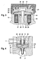
- FIG. 3 is a section of an inventively designed pressure control valve in another embodiment removed.
- the spring element 26 is formed in the form of a plate spring. Trained as a plate spring spring element 26 is disposed in the valve piston 11 surrounded spring chamber 27 on the armature plate 14 facing side. The spring element 26 is supported with one side against the end face 29 of the spring chamber 27 and with the other side against the second end face 28 of the anchor plate 14. The trained as a plate spring spring element 26 also acts as a compression spring supportive when opening the pressure control valve. 1
- the diaphragm spring shown can be used as a spring element 26, a helical compression spring, a disc spring package or any other well-known to the skilled spring geometry, which can be used as a compression spring.
- FIG. 4 shows a further embodiment of an inventively designed pressure control valve.
- a cylindrically wound coil spring 42 is used.
- the spring element 42 designed as a cylindrically wound spiral spring is supported with one side against the valve piece 5 and with the other side against a ring 43 which rests on the level 32 of the valve piston 11.
- a cylindrically wound coil spring as a spring element 42, it is also possible to form a rib on the valve piston 11 instead of the ring 43, against which the spring element 42 is supported.
- conically wound coil spring as a spring element 42
- a spring element 42 which is formed as a conical helical compression spring from a band with a rectangular cross-section.
- any further known to those skilled in the form of a compression spring as spring element 42 can be used.
- To operate the pressure control valve 1 can be used in addition to the actuator described above in the form of an electromagnet and a piezo actuator or a hydraulic / mechanical actuator.
Landscapes
- Engineering & Computer Science (AREA)
- General Engineering & Computer Science (AREA)
- Mechanical Engineering (AREA)
- Physics & Mathematics (AREA)
- Fluid Mechanics (AREA)
- Chemical & Material Sciences (AREA)
- Combustion & Propulsion (AREA)
- General Physics & Mathematics (AREA)
- Automation & Control Theory (AREA)
- Safety Valves (AREA)
- Fuel-Injection Apparatus (AREA)
Description
- Im Betrieb einer selbstzündenden Verbrennungskraftmaschine mit Hochdruckspeicher wird der Systemdruck im Hochdruckspeicher dadurch konstant gehalten, dass der Hochdruckspeicher durch ein Druckregelventil verschlossen ist. Sobald der Druck im Hochdruckspeicher den Systemdruck übersteigt, öffnet das Druckregelventil, wenn der Druck wieder unter den Systemdruck gefallen ist, schließt das Druckregelventil. Hierdurch wird gewährleistet, dass die Kraftstoffeinspritzung in die Zylinder der Verbrennungskraftmaschine unter gleich bleibenden Konditionen erfolgt.
- Zur Regelung des Kraftstoffdrucks im Hochdruckspeicher von selbstzündenden Verbrennungskraftmaschinen wird eine Zumesseinheit und/oder ein Druckregelventil verwendet.
- Das Druckregelventil ist geschlossen, wenn es nicht von einer Spannung beaufschlagt ist. Aus diesem Grund wird der Kraftstoff nach dem Abstellen des Motors im Hochdruckspeicher eingeschlossen und vom Kraftstoffrücklauf abgetrennt. Die Schließkraft zum Verschließen des Hochdruckspeichers wird von einem Federelement erzeugt, welches oberhalb der Ankerplatte des Aktors zur Steuerung des Ventils angebracht ist und das Schließelement an dem der Ankerplatte gegenüberliegenden Ende des Ventilkolbens in seinen Sitz stellt. Ein solches Druckregelventil ist aus Dieselmotor-Management, 2. Auflage, Vieweg-Verlag, 1998, Seite 270-271 bekannt.
-
US 4 905 960 A offenbart ein stromlos offenes Druckregelventil. - Aus
EP 0 267 162 A2 ist ein Druckregelventil bekannt, bei welchem ein Federelement auf eine Platte am Ventilkolben wirkt und so das Schließelement in seinen Sitz stellt. - Beim Abkühlen des Hochdruckspeichers verringert sich das Volumen des darin eingeschlossenen Kraftstoffs und erzeugt so einen starken Druckabfall. Bei Einspritzsystemen, bei denen die Injektoren jeweils mit einem Magnetventil betrieben werden, kann über die Rücklaufleitung der Injektoren Kraftstoff in den Hochdruckspeicher nachströmen, da die Rücklaufleitungen der Injektoren über Führungsleckage im Kraftstoffinjektor mit dem Hochdruckspeicher verbunden sind.
- Bei Kraftstoffinjektoren, die mit Piezoaktoren betrieben werden, tritt keine Führungsleckage auf. Somit kann kein Kraftstoff aus den Rücklaufleitungen der Injektoren in den Hochdruckspeicher gelangen. Sobald der Kraftstoffdruck im Hochdruckspeicher unter den Dampfdruck der im Kraftstoff gelösten Luft gesunken ist, gast die Luft aus, so dass neben dem flüssigen Kraftstoff auch eine Gasphase im Hochdruckspeicher enthalten ist.
- Beim Start der Verbrennungskraftmaschine muss das im Hochdruckspeicher enthaltene Gas durch die Hochdruckpumpe komprimiert werden, damit sich im Hochdruckspeicher der für den Betrieb notwendige Druck aufbaut. Abhängig von der Starttemperatur der Verbrennungskraftmaschine sind hierzu mehrere Motorumdrehungen notwendig. Dies kann zu Startverzögerungen im Bereich von 1 bis 2 Sekunden führen.
- Das erfindungsgemäß ausgebildete Druckregelventil zum Öffnen bzw. Verschließen eines Ablaufs eines Hochdruckspeichers einer Verbrennungskraftmaschine umfasst ein aktorbetätigtes Schließelement, welches eine Verbindung vom Hochdruckspeicher in eine Niederdruckleitung verschließt oder freigibt. Im Druckhalteventil ist ein Federelement derart angeordnet, dass beim Stillstand der Verbrennungskraftmaschine das Schließelement die Verbindung vom Hochdruckspeicher in die Niederdruckleitung freigibt. Hierdurch wird es ermöglicht, dass beim Stillstand der Verbrennungskraftmaschine Kraftstoff aus der Rücklaufleitung in den Hochdruckspeicher gelangen kann. Hierdurch wird vermieden, dass der Druck im Hochdruckspeicher unterhalb den Dampfdruck der im Kraftstoff gelösten Luft sinkt. Das führt dazu, dass auch beim Kaltstart der Verbrennungskraftmaschine sofort Druck im Hochdruckspeicher aufgebaut werden kann und somit die Startverzögerung beseitigt wird. Erfindungsgemäß nimmt ein Ventilkolben, dessen Abschluss eine Kalotte bildet, das kugelförmige Schließelement auf.
- In einer bevorzugten Ausführungsform des Druckregelventils ist das Federelement zum Öffnen des Schließelementes in einer Erweiterung des den Ventilkolben umschließenden Gehäuses aufgenommen und stützt sich mit einer Seite gegen das Gehäuse und mit der anderen Seite gegen die Ankerplatte des Aktors. Das Federelement ist dabei vorzugsweise eine Spiralfeder oder eine Tellerfeder. Das Federelement kann jedoch auch jede weitere dem Fachmann bekannte Form annehmen, die eine Druckkraft auf die Ankerplatte ausübt und so bei nicht bestromter Spule das Ventil öffnet.
- In einer weiteren bevorzugten Ausführungsform ist das Federelement an der dem Schließelement zugewandten Seite des Ventilkolbens angeordnet. Hierbei umschließt das Federelement den Ventilkolben und stützt sich mit einer Seite gegen ein einen Dichtsitz aufweisendes Ventilstück. Das Federelement ist dabei vorzugsweise als konisch gewickelte Spiralfeder ausgebildet, die sich mit der anderen Seite gegen einen Absatz im Ventilkolben abstützt. Durch das Ausbilden einer Platte am Ventilkolben oder durch einen Ring, welcher sich auf den Absatz im Ventilkolben abstützt, lässt sich auch eine zylindrisch geformte Spiralfeder einsetzen. Auch hier ist jedoch jedes weitere als Druckfeder wirkende Federelement, welches dem Fachmann bekannt ist, einsetzbar.
- In einer bevorzugten Ausführungsform wird das Druckregelventil mit einem elektromagnetischen Aktor betätigt. Der Aktor umfasst vorzugsweise eine Ankerplatte und eine Spule.
- In einer bevorzugten Ausführungsform ist das Druckregelventil derart ausgebildet, dass bei geöffnetem Schließelement die Ankerplatte des Aktors gegen einen Anschlag gestellt ist. Hierdurch wird der Öffnungsweg des Druckregelventils eingestellt. Durch einen nur geringen Öffnungsweg wird gewährleistet, dass das kugelförmig ausgebildete Schließelement, welches in einer bevorzugten Ausführungsform nicht mit dem Ventilkolben fest verbunden ist, an seinem Platz gehalten wird.
- Damit das Schließelement beim Öffnen des Ventils aus seinem Sitz gezogen wird, wird das kugelförmig ausgebildete Schließelement vorzugsweise durch Adhäsionskräfte in der Kalotte am Ventilkolben gehalten.
- Zur Vermeidung statischer Überbestimmtheit kann die Kalotte als Einzelteil mit plan geschliffenen Gleitflächen am Ventilkolben und Kalottenkörper ausgeführt werden. Hierdurch wird an der Kontaktstelle der plan geschliffenen Gleitflächen ein radialer Versatz zugelassen und durch einen Ölfilm zwischen den plan geschliffenen Gleitflächen an Ventilkolben und Kalottenkörper werden die zur Öffnung notwendigen adhäsiven Kräfte gewonnen, um das Ventil zu öffnen.
- Im Folgenden wird die Erfindung anhand einer Zeichnung näher beschrieben.
- Es zeigt:
- Figur 1
- einen Schnitt durch eine erste Ausführungsform eines erfindungsgemäß ausgebildeten Druckregelventils,
- Figur 1.1
- Detail X aus
Figur 1 mit kalottenförmiger Aufnahme für das Schließelement - Figur 2
- einen Schnitt durch eine zweite Ausführungsform eines erfindungsgemäß ausgebildeten Druckregelventils,
- Figur 3
- einen Ausschnitt aus einem erfindungsgemäß ausgebildeten Druckregelventil mit auf die Ankerplatte wirkender Tellerfeder,
- Figur 4
- einen Ausschnitt aus einem erfindungsgemäß ausgebildeten Druckregelventil mit zylindrisch ausgebildeter Spiralfeder.
-
Figur 1 zeigt ein Schnitt durch ein erfindungsgemäß ausgebildetes Druckregelventil in einer ersten Ausführungsform. - Ein Druckregelventil 1 verschließt die Verbindung von einem Kraftstoffhochdruckspeicher 2 zu einer Niederdruckleitung 3, die mit einem Kraftstoffvorratsbehälter 4 verbunden ist, oder gibt diese frei. Hierzu umfasst das Druckregelventil 1 ein Ventilstück 5, in welchem eine zentrale Bohrung 6 aufgenommen ist. Die Bohrung 6 geht in eine Drosselstelle 7 über, die in einem Konus 8 ausläuft. Die zentral im Ventilstück 5 angeordnete Bohrung 6 wird mit einem Schließelement 9, welches hier als Ventilkugel ausgebildet ist, verschlossen, indem das Schließelement 9 in einen Dichtsitz 10 im Konus 8 gestellt wird.
- Neben dem in
Figur 1 dargestellten kugelförmigen Schließelement 9, welches mittels eines Ventilkolbens 11 geführt wird, mit dem Ventilkolben 11 aber nicht fest verbunden ist, kann das Schließelement 9 auch fest mit dem Ventilkolben 11 verbunden sein und zum Beispiel als kugelförmiger oder kegelförmiger Abschluss des Ventilkolbens 11 ausgebildet sein. Auch kann an Stelle des hier dargestellten Sitz-Ventils ein Schieber-Ventil oder Flachsitz-Ventil eingesetzt werden. - Der Ventilkolben 11 ist zur Steuerung des Schließelementes 9 in einer Führung 12 in einem Ventilgehäuse 13 geführt. An seiner dem Schließelement 9 abgewandten Seite ist der Ventilkolben 11 mit einer Ankerplatte 14 versehen. Bei der Bestromung einer im Ventilgehäuse 13 aufgenommenen Magnetspule 15 wird die Ankerplatte 14 von der Magnetspule 15 angezogen. Hierdurch bewegt sich der Ventilkolben 11 in Richtung der Bohrung 6 im Ventilstück 5 und stellt das Schließelement 9 in seinen Schließsitz 10. Die Spannungsversorgung der Magnetspule 15 erfolgt über einen Deckel 16, der in einem vorzugsweise aus Kunststoff gefertigten Steckergehäuse 17 aufgenommen ist. Der elektrische Anschluss erfolgt dabei über Steckerpins 18. Eine flüssigkeitsdichte Verbindung des Steckergehäuses 17 mit dem Ventilgehäuse 13 wird dadurch erreicht, dass zwischen dem Ventilgehäuse 13 und dem Steckergehäuse 17 eine Labyrinthdichtung 19 ausgebildet ist. In einer bevorzugten Ausführungsform wird das Steckergehäuse 17 direkt in einem Spritzgussprozess auf das Ventilgehäuse 13 gespritzt.
- Zwischen dem Ventilgehäuse 13 und dem Steckergehäuse 17 befindet sich ein Abschlussstück 20, welches das Ventilgehäuse 13 verschließt. Um das Austreten von Kraftstoff durch Leckage aus dem Druckregelventil 1 zu vermeiden, ist zwischen dem Abschlussstück 20 und dem Ventilgehäuse 13 ein Dichtring 21 angeordnet. Der Dichtring 21 ist vorzugsweise ein O-Ring, es eignet sich aber auch jeder weitere, dem Fachmann bekannte Dichtring.
- Das Abschlussstück 20 ist so ausgebildet, dass zwischen der Ankerplatte 14 und dem Abschlussstück 20 ein Hohlraum 22 ausgebildet wird. Gleichzeitig dient das Abschlussstück 20 als Anschlag zur Wegbegrenzung des Ventilkolbens 11. Hierzu ist zwischen einer ersten Stirnseite 24 der Ankerplatte 14 und einer Stirnfläche 25 des Abschlussstückes 20 ein Spalt 23 ausgebildet. Die Höhe des Spaltes 20 entspricht dabei der im Öffnungsweg des Ventilkolbens 11.
- Wenn die Spule 15 stromlos geschaltet wird, bewegt sich der Ventilkolben 11 in Richtung des Abschlussstückes 20. Hierdurch hebt sich das Schließelement 9 aus seinem Dichtsitz 10 und gibt über die Bohrung 6 und die Drosselstelle 7 die Verbindung aus dem Hochdruckspeicher 2 in die Niederdruckleitung 3 frei. Der Öffnungsvorgang wird durch ein Federelement 26 unterstützt, welches in einem den Ventilkolben 11 umgebenden Federraum 27 aufgenommen ist. Das Federelement 26 ist als Druckfeder ausgebildet und stützt sich mit einer Seite auf die zweite Stirnseite 28 der Ankerplatte 14 und mit der anderen Seite auf eine Stirnseite 29 des Federraums 27. Durch die Federkraft des Federelementes 26 wird so bei nicht bestromter Magentspule 15 die Ankerplatte 14 in Richtung des Abschlussstückes 20 gedrückt. Die Öffnungsbewegung des Ventilkolbens 11, der mit der Ankerplatte 14 fest verbunden ist, wird dadurch gestoppt, dass die erste Stirnseite 24 der Ankerplatte 14 an die Stirnfläche 25 des Abschlussstückes 20 anschlägt. Der Öffnungsweg des Ventilkolbens 11 ist dabei so ausgewählt, dass bei einem kugelförmig ausgebildeten Schließelement 9, welches vorzugsweise frei beweglich aufgenommen ist, dieses sich aus seinem Dichtsitz 10 hebt, aber nicht aus dem Konus 8 am Ventilkolben 11 vorbei seine Position verlassen kann.
- An der dem Schließelement 9 zugewandeten Seite ist der Ventilkolben 11 von einem Ventilraum 30 umschlossen. Aus dem Ventilraum 30 verläuft eine Bohrung 31, über die der Ventilraum 30 mit der Niederdruckleitung 3 verbunden ist. Bei der in
Figur 1 dargestellten Ausführungsform ist der Ventilkolben 11 auf der dem Ventilraum 30 zugewandten Seite in einem kleineren Durchmesser ausgeführt als entlang der Führung 12. Hierdurch ist am Ventilkolben 11 eine Stufe 32 ausgebildet. Der Ventilkolben 11 endet in einem konischen Abschluss 33. - Der konische Abschluss 33 weist, wie in
Figur 1.1 dargestellt, eine Kalotte 44 auf, die das kugelförmig ausgebildete Schließelement 9 aufnimmt. Bei dem konischen Abschluss 33 des Ventilkolbens 11 mit Kalotte 44 ist zwischen der Kalotte 44 und dem Schließelement 9 vorzugsweise ein Ölfilm ausgebildet. Die durch den Ölfilm entstehenden Adhäsionskräfte führen dazu, dass beim Öffnen des Druckregelventils 1 das Schließelement 9 aus dem Schließsitz 10 gezogen wird und so die Verbindung zwischen dem Hochdruckspeicher 2 und der Niederdruckleitung 3 sicher geöffnet wird. - Um zu vermeiden, dass aus dem Hochdruckspeicher 2 Verunreinigungen in das Druckregelventil 1 gelangen und so möglicherweise die Dichtfunktion des Schließelements 9 gestört wird, ist auf der in den Hochdruckspeicher 2 weisenden Seite des Ventilstücks 5 in einer bevorzugten Ausführungsform ein Filterelement 34 angeordnet.
- Die zur einwandfreien Funktion des Druckhalteventils 1 erforderliche Maßhaltigkeit wird durch einen Distanzring 35 gewährleistet, der zwischen dem Ventilstück 5 und dem Ventilgehäuse 13 angeordnet ist. Über die Dicke des Distanzrings 35 lässt sich das Ventilstück 5 so positionieren, dass das Schließelement 9 bei geschlossenem Druckregelventil 1 so in seinem Schließsitz 10 gestellt ist, das kein Kraftstoff aus dem Hochdruckspeicher 2 ausströmen kann. Die Befestigung des Distanzringes 35 und des Ventilstücks 5 im Ventilgehäuse 13 erfolgt vorzugsweise formschlüssig mittels einer Bördelkante 36. Eine druck- und flüssigkeitsdichte Verbindung zwischen dem Ventilstück 5 und dem Gehäuse 37 des Hochdruckspeichers 2 wird dadurch erreicht, dass am Ventilstück 5 eine Beißkante 38 ausgebildet ist. Das Ventilstück 5 wird mit der Beißkante 38 gegen das Gehäuse 37 des Hochdruckspeichers 2 gepresst. Hierzu wird das Ventilgehäuse 13 mit einer Gewindehülse 39 im Gehäuse 37 des Hochdruckspeichers 2 verschraubt. Die notwendige Anpresskraft, die erforderlich ist, um eine duckdichte Verbindung zwischen dem Ventilstück 5 und dem Gehäuse 37 des Hochdruckspeichers 2 zu erreichen, wird durch einen im Ventilgehäuse 13 aufgenommenen Sprengring 40 erreicht. Die Gewindehülse 39 drückt gegen den Sprengring 40, wodurch das Ventilgehäuse 13 in Richtung des Hochdruckspeichers 2 geführt wird. Gleichzeitig führt eine im Hochdruckspeicher 2 auf das Druckregelventil 1 wirkende Druckkraft oder eine außen auf das Druckregelventil 1 aufgebrachte Zugkraft dazu, dass der Sprengring 40 gegen die Gewindehülse 39 gedrückt wird. Über das Gewinde 41 ist Gewindehülse 39 kraftschlüssig mit dem Gehäuse 37 des Hochdruckspeichers 2 verbunden, so dass bei einer in Richtung auf die Gewindehülse 39 wirkende Kraft auf den Sprengring 40 der Sprengring 40 und damit das Ventilgehäuse 13 an seiner Position gehalten wird.
-
Figur 2 zeigt einen Schnitt durch eine zweite Ausführungsform eines erfindungsgemäß gebildeten Druckregelventils. - Im Unterschied zu der in
Figur 1 dargestellten Ausführungsform ist hier ein Federelement 42 im Ventilraum 30 aufgenommen. Dafür entfällt das inFigur 1 dargestellte Federelement 26, welches auf die Ankerplatte 14 wirkt. - Bei der in
Figur 2 dargestellten Ausführungsform ist das Federelement 42 als konisch gewickelte Spiralfeder ausgebildet. Mit einer Seite stützt sich das Federelement 42 gegen die Stufe 32 im Ventilkolben 11, mit der anderen Seite gegen das Ventilstück 5. Das Federelement 42 ist als Druckfeder ausgebildet, so dass es unterstützend beim Öffnen des Druckregelventils 1 wirkt. - Der Öffnungsweg des Ventilkolbens 11 wird auch hier dadurch begrenzt, dass die erste Stirnseite 24 der Ankerplatte 14 an die Stirnfläche 25 des Abschlussstücks 20 anschlägt. Die Breite des Spaltes 23 zwischen der Ankerplatte 14 und dem Abschlussstück 20 entspricht dabei der vom Ventilkolben 11 zurückgelegten Weglänge. Auch hier ist die Weglänge so gewählt, dass das lose im Konus 8 des Ventilstücks 5 aufgenommene kugelförmig ausgebildete Schließelement 9 nicht aus dem Konus 8 herausfallen kann. Zum Verschließen des Druckregelventils 1 wird das Schließelement 9 vorzugsweise mittels einer plan geschliffenen Stirnfläche des konischen Abschlusses 33 des Ventilkegels 11 in den Dichtsitz 10 gestellt. Neben der plan geschliffenen Abschlussfläche kann die Abschlussfläche auch in Form einer Kalotte 44 (vgl.
Figur 1.1 ) gestaltet sein, welche das kugelförmig ausgebildete Schließelement 9 aufnimmt. In einer bevorzugten Ausführungsform befindet sich zwischen dem kugelförmig ausgebildetem Schließelement 9 und der Kalotte 44 ein Ölfilm, so dass das kugelförmig ausgebildete Schließelement 9 aufgrund der dadurch entstehenden Adhäsionskräfte beim Öffnen des Druckregelventils 1 aus seinem Dichtsitz 10 gezogen wird. -
Figur 3 ist ein Ausschnitt aus einem erfindungsgemäß ausgebildeten Druckregelventil in einer weiteren Ausführungsform entnehmbar. - Bei der in
Figur 3 dargestellten Ausführungsform ist an Stelle des als Spiralfeder ausgebildeten Federelementes 26, wie es inFigur 1 dargestellt ist, das Federelement 26 in Form einer Tellerfeder ausgebildet. Das als Tellerfeder ausgebildete Federelement 26 ist in dem den Ventilkolben 11 umgebenen Federraum 27 auf der der Ankerplatte 14 zugewandten Seite angeordnet. Das Federelement 26 stützt sich mit einer Seite gegen die Stirnseite 29 des Federraums 27 ab und mit der anderen Seite gegen die zweite Stirnseite 28 der Ankerplatte 14. Das als Tellerfeder ausgebildete Federelement 26 wirkt auch hier als Druckfeder unterstützend beim Öffnen des Druckregelventils 1. - Neben der in
Figur 1 dargestellten Spiralfeder und der inFigur 3 dargestellten Tellerfeder kann als Federelement 26 auch eine Schraubendruckfeder, ein Tellerfederpaket oder jede beliebige weitere dem Fachmann bekannte Federgeometrie, die sich als Druckfeder einsetzen lässt, verwendet werden. -
Figur 4 zeigt eine weitere Ausführungsform eines erfindungsgemäß ausgebildeten Druckregelventils. - An Stelle der in
Figur 2 gezeigten konisch gewickelten Spiralfeder als Federelement 42 ist bei der inFigur 4 dargestellten Ausführungsform eine zylindrisch gewickelte Spiralfeder 42 eingesetzt. Das als zylindrisch gewickelte Spiralfeder ausgeführte Federelement 42 stützt sich mit einer Seite gegen das Ventilstück 5 und mit der anderen Seite gegen einen Ring 43, der auf der Stufe 32 des Ventilkolbens 11 aufliegt. Für den Einsatz einer zylindrisch gewickelten Spiralfeder als Federelement 42 ist es auch möglich, an Stelle des Rings 43 eine Rippe am Ventilkolben 11 auszubilden, gegen welche sich das Federelement 42 abstützt. - Neben der in
Figur 2 dargestellten konisch gewickelten Spiralfeder als Federelement 42 ist es auch möglich, ein Federelement 42 einzusetzen, welches als kegelige Schrauben- Druckfeder aus einem Band mit rechteckigem Querschnitt geformt ist. Weiterhin ist es möglich, an Stelle der in denFiguren 2 und4 dargestellten Federelemente 42 in Form von konisch bzw. zylindrisch gewickelten Schraubenfedern auch Tellerfedern oder ein Tellerfederpaket zu verwenden. Weiterhin ist jede weitere dem Fachmann bekannte Form einer Druckfeder als Federelement 42 einsetzbar. - Zum Betrieb des Druckregelventils 1 lässt sich neben dem vorstehend beschriebenen Aktor in Form eines Elektromagneten auch ein Piezo-Aktor oder ein hydraulisch/mechanischer Steller einsetzen.
-
- 1
- Druckregelventil
- 2
- Hochdruckspeicher
- 3
- Niederdruckleitung
- 4
- Kraftstoffvorratsbehälter
- 5
- Ventilstück
- 6
- Bohrung
- 7
- Drosselstelle
- 8
- Konus
- 9
- Schließelement
- 10
- Schließsitz
- 11
- Ventilkolben
- 12
- Führung
- 13
- Ventilgehäuse
- 14
- Ankerplatte
- 15
- Magnetspule
- 16
- Stecker
- 17
- Steckergehäuse
- 18
- Steckerpins
- 19
- Labyrinthdichtung
- 20
- Abschlussstück
- 21
- Dichtring
- 22
- Hohlraum
- 23
- Spalt
- 24
- Erste Stirnseite der Ankerplatte 14
- 25
- Stirnfläche des Abschlussstücks 20
- 26
- Federelement
- 27
- Federraum
- 28
- Zweite Stirnseite der Ankerplatte 14
- 29
- Stirnseite des Federraums 27
- 30
- Ventilraum
- 31
- Bohrung
- 32
- Stufe
- 33
- Konischer Abschluss
- 34
- Filterelement
- 35
- Distanzring
- 36
- Bördelkante
- 37
- Gehäuse des Hochdruckspeichers 2
- 38
- Beißkante
- 39
- Gewindehülse
- 40
- Sprengring
- 41
- Gewinde
- 42
- Federelement
- 43
- Ring
- 44
- Kalotte
Claims (10)
- Druckhalteventil zum Öffnen bzw. Verschließen eines Ablaufs eines Hochdruckspeichers (2) einer Verbrennungskraftmaschine, ein aktorbetätigtes kugelförmiges Schließelement (9) umfassend, welches eine Verbindung vom Hochdruckspeicher (2) in eine Niederdruckleitung (3) verschließt oder freigibt, und mit einem Federelement (26, 42), welches derart angeordnet ist, dass beim Stillstand der Verbrennungskraftmaschine das Schließelement (9) die Verbindung vom Hochdruckspeicher (2) in die Niederdruckleitung (3) freigibt, dadurch gekennzeichnet, dass ein Ventilkolben (11), dessen Abschluss eine Kalotte (44) bildet, das kugelförmige Schließelement (9) aufnimmt.
- Druckhalteventil nach Anspruch 1, dadurch gekennzeichnet, dass das kugelförmige Schließelement (9) durch Adhäsionskräfte in der Kalotte (44) gehalten ist und so beim Öffnen des Druckregelventils (1) aus dem Dichtsitz (10) gezogen wird.
- Druckregelventil nach Anspruch 1 oder 2, dadurch gekennzeichnet, dass das Federelement (26) in einem Federraum (27) im Ventilgehäuse (13), einen Ventilkolben (11) umschließend, aufgenommen ist und sich mit einer Seite gegen eine Ankerplatte (14) des Aktors und mit der anderen Seite gegen eine Stirnseite (29) des Federraums (27) abstützt.
- Druckregelventil nach Anspruch 3, dadurch gekennzeichnet, dass das Federelement (26) eine Spiralfeder ist.
- Druckregelventil nach Anspruch 3, dadurch gekennzeichnet, dass das Federelement (26) eine Tellerfederfeder ist.
- Druckregelventil nach Anspruch 1, dadurch gekennzeichnet, dass das Federelement (42) an der dem Schließelement (9) zugewandten Seite den Ventilkolben (11) umschließt und sich mit einer Seite gegen ein einen Schließsitz (10) aufweisendes Ventilstück (5) abstützt.
- Druckregelventil nach Anspruch 6, dadurch gekennzeichnet, dass das Federelement (42) eine konisch gewickelte Spiralfeder ist und sich mit der vom Ventilstück (5) entfernten Seite gegen eine Stufe (32) vom Ventilkolben (11) abstützt.
- Druckregelventil nach Anspruch 6, dadurch gekennzeichnet, dass das Federelement (42) eine zylindrisch ausgebildete Spiralfeder ist, die sich mit der dem Ventilstück (5) abgewandten Seite auf einen den Ventilkolben (11) umschließenden Ring (43) abstützt.
- Druckregelventil nach einem der Ansprüche 1 bis 8, dadurch gekennzeichnet, dass der Aktor eine Ankerplatte (14) und eine Magnetspule (15) umfasst.
- Druckregelventil nach Anspruch 9, dadurch gekennzeichnet, dass die Ankerplatte (14) in geöffnetem Zustand gegen einen Anschlag (24, 25) gestellt ist.
Applications Claiming Priority (2)
| Application Number | Priority Date | Filing Date | Title |
|---|---|---|---|
| DE102004002964A DE102004002964A1 (de) | 2004-01-21 | 2004-01-21 | Druckregelventil für einen Hochdruckspeicher einer Verbrennungskraftmaschine |
| DE102004002964 | 2004-01-21 |
Publications (2)
| Publication Number | Publication Date |
|---|---|
| EP1557597A1 EP1557597A1 (de) | 2005-07-27 |
| EP1557597B1 true EP1557597B1 (de) | 2012-01-11 |
Family
ID=34625729
Family Applications (1)
| Application Number | Title | Priority Date | Filing Date |
|---|---|---|---|
| EP04028091A Expired - Lifetime EP1557597B1 (de) | 2004-01-21 | 2004-11-26 | Druckregelventil für einen Hochdruckspeicher einer Verbrennungskraftmaschine |
Country Status (2)
| Country | Link |
|---|---|
| EP (1) | EP1557597B1 (de) |
| DE (1) | DE102004002964A1 (de) |
Families Citing this family (19)
| Publication number | Priority date | Publication date | Assignee | Title |
|---|---|---|---|---|
| DE102005012940A1 (de) | 2005-03-21 | 2006-09-28 | Robert Bosch Gmbh | Kraftstoffeinspritzeinrichtung für eine Brennkraftmaschine |
| FR2899949B1 (fr) * | 2006-04-13 | 2008-07-11 | Eaton Sa Monegasque | Electrovanne de regulation de pression |
| DE102006053847A1 (de) * | 2006-11-14 | 2008-05-15 | Hydraulik-Ring Gmbh | Hochdruckkraftstoffsystem mit Volumenkompensation, insbesondere für die Abkühlphase des Hochdrucksystems |
| DE102007062176A1 (de) | 2007-12-21 | 2009-06-25 | Robert Bosch Gmbh | Druckregelventil zur Regelung des Drucks in einem Hochdruck-Kraftstoffspeicher |
| DE102010043097A1 (de) | 2010-10-29 | 2012-05-03 | Robert Bosch Gmbh | Druckregelventil |
| DE102010043092A1 (de) | 2010-10-29 | 2012-05-03 | Robert Bosch Gmbh | Druckregelventil |
| FR2973092B1 (fr) * | 2011-03-25 | 2016-09-02 | Bosch Gmbh Robert | Dispositif d'obturation, regulateur de pression comportant un tel dispositif, dispositif d'injection diesel comportant un tel regulateur, moteur diesel et vehicule comportant un tel moteur |
| EP2535554A1 (de) * | 2011-06-15 | 2012-12-19 | Delphi Technologies Holding S.à.r.l. | Elektroventil zur Common-Rail-Entladung |
| DE102011105586B4 (de) * | 2011-06-27 | 2014-12-24 | Staiger Gmbh & Co. Kg | Ventil |
| FR2988140B1 (fr) | 2012-03-15 | 2016-02-05 | Bosch Gmbh Robert | Soupape de regulation de pression d'accumulateur haute pression de carburant de moteur a combustion interne |
| DE102012209226A1 (de) * | 2012-05-31 | 2013-12-05 | Robert Bosch Gmbh | Druckregelventil |
| DE102012216534A1 (de) * | 2012-09-17 | 2014-03-20 | Robert Bosch Gmbh | Druckregelventil für ein Kraftstoffeinspritzsystem |
| DE102012221157A1 (de) | 2012-11-20 | 2014-05-22 | Robert Bosch Gmbh | Druckregelventil für einen Hochdruckspeicher eines Verbrennungsmotors |
| DE102013200634B4 (de) | 2013-01-17 | 2024-03-28 | Robert Bosch Gmbh | Druckregelventil für einen Kraftstoff-Hochdruckspeicher |
| FR3002003A1 (fr) * | 2013-02-11 | 2014-08-15 | Bosch Gmbh Robert | Procede de realisation d'une soupape a commande electromagnetique |
| DE102014202278A1 (de) | 2014-02-07 | 2015-08-13 | Robert Bosch Gmbh | Druckregelventil für einen Hochdruckspeicher |
| DE102014206060A1 (de) * | 2014-03-31 | 2015-10-01 | Robert Bosch Gmbh | Druckregelventil für einen Hochdruckspeicher |
| US20150345448A1 (en) * | 2014-05-29 | 2015-12-03 | Caterpillar Inc. | Flow limiter and filter assembly for a fuel system of an engine |
| DE102015205114B4 (de) | 2015-03-20 | 2022-08-04 | Volkswagen Aktiengesellschaft | Verfahren zur Vermeidung zu hoher Systemdrücke in Common-Rail-Systemen |
Family Cites Families (9)
| Publication number | Priority date | Publication date | Assignee | Title |
|---|---|---|---|---|
| JPH07122422B2 (ja) * | 1986-05-02 | 1995-12-25 | 日本電装株式会社 | 燃料噴射装置 |
| IT208326Z2 (it) | 1986-11-07 | 1988-05-28 | Altecna Azienda Della Weber S | Elettrovalvola regolatrice di pressione particolarmente per circuiti ad alta pressione di impianti di iniezione del combustibile per motori a combustione interna |
| US4905960A (en) * | 1988-12-08 | 1990-03-06 | Cummins Engine Company, Inc. | Solenoid valve stroke adjustment locking mechanism and method of forming the same |
| US5413308A (en) * | 1993-09-03 | 1995-05-09 | The Horton Company | Fail-open solenoid actuated valve |
| FR2783890B1 (fr) * | 1998-09-29 | 2000-12-01 | Eaton Corp | Electrovanne de regulation de pression |
| DE19952774B4 (de) * | 1999-11-03 | 2004-03-11 | Daimlerchrysler Ag | Vorrichtung zum Ablassen von Fluid aus einem System |
| DE10236314B4 (de) * | 2001-09-08 | 2005-06-16 | Robert Bosch Gmbh | Einspritzanlage für Brennkraftmaschinen mit verbesserten Starteigenschaften |
| JP2003097749A (ja) * | 2001-09-26 | 2003-04-03 | Denso Corp | 電磁式流体制御装置 |
| JP2003176765A (ja) * | 2001-12-11 | 2003-06-27 | Denso Corp | コモンレール式燃料噴射システム |
-
2004
- 2004-01-21 DE DE102004002964A patent/DE102004002964A1/de not_active Withdrawn
- 2004-11-26 EP EP04028091A patent/EP1557597B1/de not_active Expired - Lifetime
Also Published As
| Publication number | Publication date |
|---|---|
| DE102004002964A1 (de) | 2005-08-11 |
| EP1557597A1 (de) | 2005-07-27 |
Similar Documents
| Publication | Publication Date | Title |
|---|---|---|
| EP1772618B1 (de) | Common-Rail-Injektor | |
| DE69708396T2 (de) | Piezoelektrisch gesteuertes Einspritzventil mit hydraulischer Vergrösserung des Hubs | |
| EP1557597A1 (de) | Druckregelventil für einen Hochdruckspeicher einer Verbrennungskraftmaschine | |
| EP1492954B1 (de) | Einstellbares druckregelventil für kraftstoffeinspritzsysteme | |
| EP2016278B1 (de) | Druckregelventil mit notfahr- und belüftungsfunktion | |
| WO2005075811A1 (de) | Kraftstoffinjektor mit direktgesteuertem einspritzventilglied | |
| DE102016220326A1 (de) | Ventil zum Zumessen eines gasförmigen oder flüssigen Kraftstoffs | |
| WO2016058805A1 (de) | Elektromagnetisch betätigbares einlassventil und hochdruckpumpe mit einlassventil | |
| EP1967726B1 (de) | Magnetventilinjektor | |
| EP1144842A1 (de) | Injektor für ein kraftstoffeinspritzsystem für brennkraftmaschinen mit in den ventilsteuerraum ragender düsennadel | |
| EP3387247A1 (de) | Elektromagnetisch betätigbares einlassventil und hochdruckpumpe mit einlassventil | |
| EP2733345A1 (de) | Druckregelventil für einen Hochdruckspeicher eines Verbrennungsmotors | |
| EP2185807B1 (de) | Steuerventil für einen kraftstoffinjektor | |
| DE102006041977A1 (de) | Injektor zum Einspritzen von Kraftstoff | |
| EP3032090B1 (de) | Schalt- oder druckregelventil für ein kraftstoffeinspritzsystem | |
| DE102013222650A1 (de) | Brennstoffeinspritzventil | |
| DE102013222483A1 (de) | Druckregelventil | |
| DE102020209574A1 (de) | Elektromagnetisch betätigbares Einlassventil und Hochdruckpumpe mit Einlassventil | |
| DE102012216534A1 (de) | Druckregelventil für ein Kraftstoffeinspritzsystem | |
| EP3365551A1 (de) | Elektromagnetisch betätigbares einlassventil und hochdruckpumpe mit einlassventil | |
| WO2019197067A1 (de) | Elektromagnetisch betätigbares einlassventil und hochdruckpumpe mit einlassventil | |
| DE3410431A1 (de) | Elektromagnetisch zu betaetigendes fluidsteuerventil | |
| DE102018219233A1 (de) | Elektromagnetisch betätigbares Einlassventil und Hochdruckpumpe mit Einlassventil | |
| DE102019220172A1 (de) | Kraftstoffinjektor für eine Brennkraftmaschine | |
| DE102015210525A1 (de) | Elektromagnetisch betätigbares Einlassventil und Hochdruckpumpe mit Einlassventil |
Legal Events
| Date | Code | Title | Description |
|---|---|---|---|
| PUAI | Public reference made under article 153(3) epc to a published international application that has entered the european phase |
Free format text: ORIGINAL CODE: 0009012 |
|
| AK | Designated contracting states |
Kind code of ref document: A1 Designated state(s): AT BE BG CH CY CZ DE DK EE ES FI FR GB GR HU IE IS IT LI LU MC NL PL PT RO SE SI SK TR |
|
| AX | Request for extension of the european patent |
Extension state: AL HR LT LV MK YU |
|
| AKX | Designation fees paid | ||
| 17P | Request for examination filed |
Effective date: 20060420 |
|
| RBV | Designated contracting states (corrected) |
Designated state(s): DE FR GB IT |
|
| RIN1 | Information on inventor provided before grant (corrected) |
Inventor name: SCHOEGGL, FRANK Inventor name: SCHEURER, HANS-PETER Inventor name: BEUCHE, VOLKER Inventor name: ZERLE, LORENZ Inventor name: BUSCH, ROGER |
|
| 17Q | First examination report despatched |
Effective date: 20100322 |
|
| GRAP | Despatch of communication of intention to grant a patent |
Free format text: ORIGINAL CODE: EPIDOSNIGR1 |
|
| GRAS | Grant fee paid |
Free format text: ORIGINAL CODE: EPIDOSNIGR3 |
|
| GRAA | (expected) grant |
Free format text: ORIGINAL CODE: 0009210 |
|
| AK | Designated contracting states |
Kind code of ref document: B1 Designated state(s): DE FR GB IT |
|
| REG | Reference to a national code |
Ref country code: GB Ref legal event code: FG4D Free format text: NOT ENGLISH |
|
| REG | Reference to a national code |
Ref country code: DE Ref legal event code: R096 Ref document number: 502004013214 Country of ref document: DE Effective date: 20120308 |
|
| PLBE | No opposition filed within time limit |
Free format text: ORIGINAL CODE: 0009261 |
|
| STAA | Information on the status of an ep patent application or granted ep patent |
Free format text: STATUS: NO OPPOSITION FILED WITHIN TIME LIMIT |
|
| 26N | No opposition filed |
Effective date: 20121012 |
|
| REG | Reference to a national code |
Ref country code: DE Ref legal event code: R097 Ref document number: 502004013214 Country of ref document: DE Effective date: 20121012 |
|
| PGFP | Annual fee paid to national office [announced via postgrant information from national office to epo] |
Ref country code: GB Payment date: 20121122 Year of fee payment: 9 Ref country code: IT Payment date: 20121126 Year of fee payment: 9 |
|
| GBPC | Gb: european patent ceased through non-payment of renewal fee |
Effective date: 20131126 |
|
| PG25 | Lapsed in a contracting state [announced via postgrant information from national office to epo] |
Ref country code: IT Free format text: LAPSE BECAUSE OF NON-PAYMENT OF DUE FEES Effective date: 20131126 |
|
| PG25 | Lapsed in a contracting state [announced via postgrant information from national office to epo] |
Ref country code: GB Free format text: LAPSE BECAUSE OF NON-PAYMENT OF DUE FEES Effective date: 20131126 |
|
| REG | Reference to a national code |
Ref country code: FR Ref legal event code: PLFP Year of fee payment: 12 |
|
| PGFP | Annual fee paid to national office [announced via postgrant information from national office to epo] |
Ref country code: FR Payment date: 20151124 Year of fee payment: 12 |
|
| REG | Reference to a national code |
Ref country code: FR Ref legal event code: ST Effective date: 20170731 |
|
| PG25 | Lapsed in a contracting state [announced via postgrant information from national office to epo] |
Ref country code: FR Free format text: LAPSE BECAUSE OF NON-PAYMENT OF DUE FEES Effective date: 20161130 |
|
| PGFP | Annual fee paid to national office [announced via postgrant information from national office to epo] |
Ref country code: DE Payment date: 20240123 Year of fee payment: 20 |
|
| REG | Reference to a national code |
Ref country code: DE Ref legal event code: R071 Ref document number: 502004013214 Country of ref document: DE |