EP1557697A2 - Procédé de protection et détecteur optoéléctronique - Google Patents
Procédé de protection et détecteur optoéléctronique Download PDFInfo
- Publication number
- EP1557697A2 EP1557697A2 EP05009625A EP05009625A EP1557697A2 EP 1557697 A2 EP1557697 A2 EP 1557697A2 EP 05009625 A EP05009625 A EP 05009625A EP 05009625 A EP05009625 A EP 05009625A EP 1557697 A2 EP1557697 A2 EP 1557697A2
- Authority
- EP
- European Patent Office
- Prior art keywords
- tool
- boundary surface
- movement
- volume
- monitoring
- Prior art date
- Legal status (The legal status is an assumption and is not a legal conclusion. Google has not performed a legal analysis and makes no representation as to the accuracy of the status listed.)
- Ceased
Links
- 230000005693 optoelectronics Effects 0.000 title claims abstract description 15
- 238000000034 method Methods 0.000 title claims description 24
- 238000012544 monitoring process Methods 0.000 claims abstract description 53
- 230000007704 transition Effects 0.000 claims abstract description 5
- 238000003754 machining Methods 0.000 claims description 7
- 230000001960 triggered effect Effects 0.000 claims description 7
- 238000001514 detection method Methods 0.000 claims description 4
- 238000011156 evaluation Methods 0.000 claims description 3
- 230000009849 deactivation Effects 0.000 claims 1
- 230000007717 exclusion Effects 0.000 claims 1
- 239000011159 matrix material Substances 0.000 abstract description 2
- 230000004044 response Effects 0.000 description 5
- 208000027418 Wounds and injury Diseases 0.000 description 4
- 230000005540 biological transmission Effects 0.000 description 4
- 230000006378 damage Effects 0.000 description 4
- 208000014674 injury Diseases 0.000 description 4
- 238000013461 design Methods 0.000 description 3
- 230000008569 process Effects 0.000 description 3
- 238000013459 approach Methods 0.000 description 2
- 230000001681 protective effect Effects 0.000 description 2
- 230000003068 static effect Effects 0.000 description 2
- 208000034656 Contusions Diseases 0.000 description 1
- 230000004888 barrier function Effects 0.000 description 1
- 238000005452 bending Methods 0.000 description 1
- 230000008901 benefit Effects 0.000 description 1
- 230000009519 contusion Effects 0.000 description 1
- 230000000694 effects Effects 0.000 description 1
- 230000001771 impaired effect Effects 0.000 description 1
- 230000035515 penetration Effects 0.000 description 1
- 238000003825 pressing Methods 0.000 description 1
- 238000000926 separation method Methods 0.000 description 1
Images


Classifications
-
- F—MECHANICAL ENGINEERING; LIGHTING; HEATING; WEAPONS; BLASTING
- F16—ENGINEERING ELEMENTS AND UNITS; GENERAL MEASURES FOR PRODUCING AND MAINTAINING EFFECTIVE FUNCTIONING OF MACHINES OR INSTALLATIONS; THERMAL INSULATION IN GENERAL
- F16P—SAFETY DEVICES IN GENERAL; SAFETY DEVICES FOR PRESSES
- F16P3/00—Safety devices acting in conjunction with the control or operation of a machine; Control arrangements requiring the simultaneous use of two or more parts of the body
- F16P3/12—Safety devices acting in conjunction with the control or operation of a machine; Control arrangements requiring the simultaneous use of two or more parts of the body with means, e.g. feelers, which in case of the presence of a body part of a person in or near the danger zone influence the control or operation of the machine
- F16P3/14—Safety devices acting in conjunction with the control or operation of a machine; Control arrangements requiring the simultaneous use of two or more parts of the body with means, e.g. feelers, which in case of the presence of a body part of a person in or near the danger zone influence the control or operation of the machine the means being photocells or other devices sensitive without mechanical contact
- F16P3/144—Safety devices acting in conjunction with the control or operation of a machine; Control arrangements requiring the simultaneous use of two or more parts of the body with means, e.g. feelers, which in case of the presence of a body part of a person in or near the danger zone influence the control or operation of the machine the means being photocells or other devices sensitive without mechanical contact using light grids
-
- B—PERFORMING OPERATIONS; TRANSPORTING
- B30—PRESSES
- B30B—PRESSES IN GENERAL
- B30B15/00—Details of, or accessories for, presses; Auxiliary measures in connection with pressing
- B30B15/28—Arrangements for preventing distortion of, or damage to, presses or parts thereof
- B30B15/285—Arrangements for preventing distortion of, or damage to, presses or parts thereof preventing a full press stroke if there is an obstruction in the working area
Definitions
- the invention relates to a method for securing a danger zone a moving, an attack point having tool, in particular a vertically downwardly moving upper tool of a press brake, wherein an opto-electronic sensor moves with the tool is monitored and the danger area, and wherein upon detection of a Engaging in the danger area a shutdown to stop the Tool movement is triggered.
- the invention further relates to a corresponding optoelectronic sensor.
- the background of the invention is the endeavor to injure an operator prevent, which works on the moving tool of a machine, for example, by the operator to be processed workpieces feeds to the tool.
- said press brake can - without suitable security measures - the upper tool a Cause injury or separation of the fingers or hands of the operator.
- the attack site the tool includes, for example, a plunger or a stamp, and it extends, in particular in said press brake, typically along a longitudinal direction, for example along a bending line or cutting edge of the moving tool.
- the danger area thus corresponds to a space area, which is partly due to the Extension of the attack site and on the other by the Nachlaufweg of the tool, so by the after triggering a shutdown signal from Tool still traveled distance is specified.
- At least one Transmitting device and a receiving device of an optoelectronic Move sensors with the tool monitors by constantly emitting and receiving a collimated transmitted light beam, whether an intervention in the danger area takes place. If this is based an interruption of the transmitted light beam is detected, a shutdown triggered, causing an immediate stop of the tool movement leads.
- a volume of space is monitored by an expanded one Transmitted transmitted light beam and by means of a matrix-shaped Spatial receiving device is received.
- a surveillance area with a boundary area monitored whose cross-section parallel to the tool movement and perpendicular to the extension direction of the point of attack of the Tool extends along a circular arc or beyond, being the center of the arc from the point of attack of the tool is arranged spaced apart in the direction of movement of the tool, and wherein the circular arc has a radius (monitoring radius), which is at least so large that the boundary surface of the surveillance area - at least on the operator side - up to the point of attack of the tool or extends radially beyond.
- the invention provides an additional safeguard against so-called dynamic interventions, ie against interferences from the movement of the operator, which occur when the tool movement is already started Has.
- dynamic interventions are typically done by the operator side, in particular obliquely from above or from the front.
- the operator is an unexpected Slipping of the workpiece to be machined noticed and therefore - regardless the already used tool movement - as immediate Reaction in the danger area grips to a readjustment perform.
- slipping the hands of the operator of during the tool movement against a stop device pressing workpiece can represent a typical dynamic engagement.
- a fuse against such dynamic Intervention by additionally monitoring at least along a boundary surface takes place, the - in any form - ultimately a Make kind of protective bell.
- the boundary surface has respect to a plane parallel to the tool movement and perpendicular to the Extension direction of the point of attack of the tool runs, a Cross-section along a circular arc or - especially in radial direction - extends beyond.
- a monitoring area with a boundary surface provided, the minimum extent - in cross section in particular is given by a circular arc.
- the center of this Circular arc is - based on the direction of movement of the tool - in front of the point of application of the tool.
- the vertical down moved upper tool of a press brake is the center of said circular arc so at a certain distance below the attack site.
- said arc has a radius that at least is chosen so large that said boundary surface is in radial Direction extends at least up to the point of attack of the tool, so that with respect to the direction of movement of the tool no monitoring Gap between the boundary surface and the point of attack of the tool.
- the invention thus ensures an improved security of the danger area against dynamic interventions. Nevertheless - as with the known safety methods and sensors - a harmless and thus permissible readjustment of the workpiece to be machined possible, namely by the surveillance area or its boundary surface is spatially limited with respect to the direction of movement of the tool, so that an intervention in the subsequent to the surveillance area Room area no shutdown triggers.
- the Monitoring area does not have to form a closed room volume. Rather, it can be based on a closed monitoring of the boundary surface the monitoring area are omitted, for example in the case that an engagement due to the geometry of the tool assembly is excluded from another direction. This applies in particular Interventions in the danger zone from the operator side of the Tool.
- the boundary surface of the surveillance area adjacent to the tool ensures that that no interference between the point of attack of the tool and the Surveillance can be done, which is especially true for fast dynamic Intervention could lead to a risk of injury.
- the boundary surface of the surveillance area is - accordingly the minimum cross-sectional dimension according to a circular arc - convexly curved with respect to the point of application of the tool.
- the cross section of the boundary surface So essentially the shape of a quarter circle or a Semicircle interrupted by the tool or its point of attack can own.
- the surveillance area essentially the shape of a circle quadrant or a circle half exhibit.
- the boundary surface of the monitoring area along the extension direction of the point of attack extends the tool.
- the boundary surface thus covers, for example the lateral surface of a cylinder segment, in particular a Quarter or half-cylinder segment.
- the boundary surface along the circular arc and / or along the extension direction the point of attack of the tool to a substantially closed monitored area, so that any intervention or Penetration of the boundary surface can be detected.
- Such closed area can be, for example, by adjacent Realize light beam.
- the boundary surface of the surveillance area is also to note that though by the aforementioned circular arc cross section the minimum extension is basically given. However, you can the course be adapted to the shape of the workpiece to be machined. Alternatively or additionally, the boundary surface may be interrupted at one point be, due to the structure of the tool an engagement anyway inherently excluded in the danger area.
- a residual height that is at a shutdown or stopping the Tool is always adhered to.
- This residual height is generally determined after the largest body part of the operator, that at dynamic Approaching the danger zone.
- the necessary residual height determined from the defined body part diameter and the permissible contusion.
- a possible residual height for example, be about 10 to 14 mm.
- the extent of the circular arc predetermining minimum monitoring radius is preferred by the response time of the optionally triggered shutdown and / or the maximum approximation or Entry speed of the operator specified, in particular by the product of response time and maximum approach speed. This ensures that even with the fastest possible Engage the shutdown process is triggered, even before that in the Surveillance area invading body part of the operator with the Tool comes into contact.
- the Surveillance radius for example, between 20 and 50 mm, in particular between 24 and 40 mm.
- the Movement speed of the tool the response time of the shutdown and / or the overtravel of the tool taken into account become.
- the monitoring radius can at least the Sum of the product of movement speed and response time on the one hand and follow-up path on the other. In this case is in particular with regard to an intervention in extension of the direction of movement the tool takes into account the entire braking distance of the tool.
- the monitoring radius for example between 6 and 16 mm, in particular between 10 and 12 mm.
- the actual carried out by means of the optoelectronic sensor Surveillance can essentially only take place along the boundary surface the surveillance area or part of it. It is also possible, in addition a surface monitoring along further the Provide surveillance area limiting surfaces, in particular along that surface which in cross section corresponds to the radius of said Arc corresponds.
- monitoring the surveillance area take place within the boundary surface, ie with respect to the entire enclosed by the boundary surface volume.
- the transition from the fast closing movement in the slow closing or machining movement is preferably carried out in a switching point, which is programmed or trained by the operator.
- the aim of the operator is to place this point as close as possible to the workpiece surface.
- the monitoring or the protective device is preferably deactivated from this switching point (so-called muting), since the protection is now carried out by the slow closing or machining movement.
- the optoelectronic sensor and receiving device for example, an arrangement of adjacent and parallel to each other may have light barriers. This is particularly advantageous if only a two-dimensional monitoring the boundary surface of the monitored area is to take place. Especially in the case that monitors only the boundary surface is, the receiving device with individual light-sensitive Components are realized.
- the transmitting device may, for example, one or more Have laser diodes or LEDs, whose transmitted light beam is expanded by means of a transmitting optics, so that this transmitting device is suitable for monitoring a volume of space.
- This can be a be provided spatially resolving receiving device, for example CCD or CMOS receiver with a row or matrix arrangement of receiving elements.
- the transmitting device and / or the receiving device preferably - only when monitoring the boundary surface - according to said circular arc or - when monitoring the entire surveillance area - within the arranged circular arc, said arrangement is based on the already mentioned cross-section parallel to the tool movement and vertical refers to the extension direction of the point of attack of the tool.
- the transmitted light beams are preferably parallel to the extension direction of the point of attack of the tool.
- the transmitting device and / or the receiving device outside the danger zone of the tool in a basically known lateral arrangement is provided.
- the transmitting device and the receiving device as so-called Active-active system in an immediate comparison be constructed, or as an active-passive system in which the transmitting device and the receiving device together face a reflector.
- the sensor according to the invention has an evaluation device based on the receiving signal of the receiving device an interruption detect the transmission light and, where appropriate, the shutdown triggers. Of course, this evaluation does not have be moved with the tool.
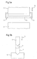
- the known Gesenkbiegepresse shown in Figs. 5a and 5b has a Upper tool 11 and a lower tool 13.
- the upper tool 11 is closed a vertically downward closing movement 15 drivable to ultimately one between the upper tool 11 and the lower tool thirteenth introduced workpiece, such as a sheet to deform.
- the Transmitting device 19 emits a transmission light bar 23 in the direction of Receiving device 21.
- the transmission light bar 23 has a rectangular Cross-section. It runs within the danger zone 17, and although with respect to the direction of the closing movement 15 of the upper tool 11 slightly spaced (Fig. 5b).
- a shutdown is triggered to the Stop closing movement 15 of the upper tool 11.
- a Shutdown occurs, for example, when in the lower part of the danger area 17 is a hand of the operator and if due the downward movement 15 of the upper tool 11 and thus the Transmitted light bar 23 the hand from a certain time to an interruption of the transmission light bar 23 performs (static engagement).
- FIGS. 1a and 1b show the monitoring according to the invention Method and sensor.
- Fig. 1a and 1b are also an upper tool 11 and a lower tool 13, on which a workpiece 25 to be deformed rests.
- the upper tool 11 initially performs a fast closing movement 15 by.
- the point of attack, so the lower tip of the upper tool 11 is designated by the reference numeral 27.
- This attack point 27 extends itself as a stamp in viewing direction.
- a monitoring area 29 which is shown in FIGS and Fig. 1b is shown hatched and by a - in Figs. 1a and 1b is shown as a solid line - limiting surface 31 is limited.
- the boundary surface 31 has on both sides of the upper tool 11 each have a section in the form of a circular arc 33.
- the two Circular arcs 33 have a common center 35, with respect to the closing movement direction 15 below the point of attack 27 of the Upper tool 11 is located.
- the dashed line in Fig. 1a radius 37 of the respective circular arc 33 is dimensioned such that the boundary surface 31 clearly above the point of attack 27 to the upper tool 11th followed.
- the boundary surface 31 has a Section 39, which is adapted to the outline of the upper tool 11, so that the monitoring area 29 substantially directly to the Upper tool 11 adjacent.
- one end of each arc extends 33 in the region of the upper tool 11 substantially in horizontal Direction, and the respective other end substantially vertical downward.
- the two circular arcs 33 form a semicircle whose course in the region of the upper tool 11 according to the section 39 of the boundary surface 31 is adapted to the shape of the upper tool 11.
- the monitoring area 29 is extended downward, namely in that the boundary surface 31 has two vertical sections 41, which adjoin the vertical end of the respective arc section 33 connect.
- the extension of the surveillance area 29 according to the vertical sections 41 downwards thus takes place by a residual amount 43rd
- the monitoring area 29 is downwardly through a horizontal section 45 of the boundary surface 31 limited.
- the monitoring of the danger area both within the surveillance area 29 and along the boundary surface 31 takes place by a - not shown - transmitting device and receiving device in a juxtaposition in a similar manner as in FIG. 5a.
- the monitoring area 29 and extend the boundary surface 31 according to FIGS. 1a and 1b in the viewing direction, that is parallel to the extension direction of the point of attack 27 of the upper tool 11th
- the procedure of the backup procedure is as follows:
- the upper tool 11 is initially activated with monitoring to a relatively fast closing movement 15 driven vertically downwards.
- the monitoring area 29, its boundary surface move 31 and thus also the center 35 of the circular arcs 33 with the upper tool 11 with.
- below the surveillance area 29 and below the horizontal portion 45 of the boundary surface 31 still engaged in the danger zone.
- the fuse method and the sensor according to the invention provide thus compared to the known security of the danger area according to Figs. 5a and 5b the advantage that a backup against dynamic Intervention is ensured by the operator. If namely during the rapid closing movement 15 an intervention in the danger area, is done for example by a so-called Nachgreif, is by the radial extent of the monitoring area 29 along the circular arcs 33 around the radius 37 ensures that a timely shutdown the movement of the upper tool 11 takes place.
- the radius 37 for example, at least chosen so large that it is the product of the Response time of the switch-off process and the highest possible approach speed corresponds to the operator.
- Figs. 2 to 4 show in respective side and cross-sectional views Further embodiments of the monitoring according to the invention.
- FIG. 2 is only on the operator facing side of the upper tool 11 provided a fuse, such that the monitoring area 29 in the cross-sectional view shown essentially occupies a quarter of a circle or related to his spatial extent comprises a quarter-cylinder segment.
- the boundary surface 31 of the surveillance area becomes 29 not specially supervised, as by the dashed Representation of the boundary surface 31 is expressed. However, it is Again, possible to monitor only the boundary surface 31.
- monitoring takes place, for example along the boundary surface 31, ie along the semicircular arc 33, the vertical sections 41 and the horizontal section 45.
- the center 35 of the circular arc 33 is here exactly around the radius 37 of the arc 33 is located below the point of attack 27.
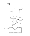
- Fig. 4 shows the minimum required extension of the boundary surface 31, which is required to provide protection against interference from the Side or from above to achieve.
- monitoring takes place only along the circular arc 33 (solid line) or along the extension of the circular arc 33rd in viewing direction.
- the circular arc 33 extends over at least 30 °, wherein the bisector of the arc 33 and the corresponding Circular segments an angle of approximately 45 ° to the horizontal forms.
- the boundary surface 31 thus extends flat convex.
- the center 35 of the arc 33 is just below the radius 37 the attack point 27 arranged.
- the extension in particular the radial extent of the Monitoring range 29 and the boundary surface 31 also over the minimum required monitoring radius can go. So corresponds the radius 37 of the circular arcs 33 shown in FIGS. 1a and 1b not necessarily the minimum required monitoring radius, but can go beyond this, for example to a complete one Enclose the bottom of the upper tool 11 to ensure. It It is also possible that the boundary surface 31 in cross section not necessarily a circular arc, but, for example, a right-angled Course has.
Landscapes
- Engineering & Computer Science (AREA)
- Mechanical Engineering (AREA)
- General Engineering & Computer Science (AREA)
- Bending Of Plates, Rods, And Pipes (AREA)
- Presses And Accessory Devices Thereof (AREA)
- Geophysics And Detection Of Objects (AREA)
- Auxiliary Devices For Machine Tools (AREA)
- Prostheses (AREA)
- Photo Coupler, Interrupter, Optical-To-Optical Conversion Devices (AREA)
- Machine Tool Sensing Apparatuses (AREA)
Applications Claiming Priority (3)
| Application Number | Priority Date | Filing Date | Title |
|---|---|---|---|
| DE10143505A DE10143505B4 (de) | 2001-09-05 | 2001-09-05 | Sicherungsverfahren und optoelektronischer Sensor |
| DE10143505 | 2001-09-05 | ||
| EP02015932A EP1291573B2 (fr) | 2001-09-05 | 2002-07-17 | Procédé de protection et détecteur optoélectronique |
Related Parent Applications (3)
| Application Number | Title | Priority Date | Filing Date |
|---|---|---|---|
| EP02015932A Division-Into EP1291573B2 (fr) | 2001-09-05 | 2002-07-17 | Procédé de protection et détecteur optoélectronique |
| EP02015932A Division EP1291573B2 (fr) | 2001-09-05 | 2002-07-17 | Procédé de protection et détecteur optoélectronique |
| EP02015932.3 Division | 2002-07-17 |
Publications (2)
| Publication Number | Publication Date |
|---|---|
| EP1557697A2 true EP1557697A2 (fr) | 2005-07-27 |
| EP1557697A3 EP1557697A3 (fr) | 2005-08-10 |
Family
ID=7697801
Family Applications (2)
| Application Number | Title | Priority Date | Filing Date |
|---|---|---|---|
| EP05009625A Ceased EP1557697A3 (fr) | 2001-09-05 | 2002-07-17 | Procédé de protection et détecteur optoéléctronique |
| EP02015932A Expired - Lifetime EP1291573B2 (fr) | 2001-09-05 | 2002-07-17 | Procédé de protection et détecteur optoélectronique |
Family Applications After (1)
| Application Number | Title | Priority Date | Filing Date |
|---|---|---|---|
| EP02015932A Expired - Lifetime EP1291573B2 (fr) | 2001-09-05 | 2002-07-17 | Procédé de protection et détecteur optoélectronique |
Country Status (5)
| Country | Link |
|---|---|
| US (2) | US6919554B2 (fr) |
| EP (2) | EP1557697A3 (fr) |
| JP (1) | JP2003181541A (fr) |
| AT (1) | ATE315202T1 (fr) |
| DE (2) | DE10143505B4 (fr) |
Families Citing this family (19)
| Publication number | Priority date | Publication date | Assignee | Title |
|---|---|---|---|---|
| EP1552214B1 (fr) * | 2002-06-11 | 2011-10-26 | Kevin Stephen Davies | Systeme de securite |
| DE10309399A1 (de) | 2003-03-04 | 2004-09-16 | Sick Ag | Sicherungsverfahren und optoelektronischer Sensor |
| DE10327388C5 (de) * | 2003-06-18 | 2011-12-08 | Leuze Lumiflex Gmbh + Co. Kg | Schutzeinrichtung |
| DE10342431A1 (de) * | 2003-09-13 | 2005-04-07 | Fiessler Elektronik Ohg | Schutzeinrichtung für Maschinen, wie Abkantpressen, Schneidemaschinen, Stanzmaschinen oder dergleichen |
| WO2005030410A1 (fr) * | 2003-09-26 | 2005-04-07 | Trumpf Maschinen Austria Gmbh & Co. Kg. | Systeme de securite comportant un dispositif de fixation reglable en hauteur |
| DE10346918A1 (de) * | 2003-10-09 | 2005-05-04 | Sick Ag | Vorrichtung mit Schutzeinrichtung |
| DE10353353A1 (de) | 2003-11-14 | 2005-06-02 | Sick Ag | Sicherheitsverfahren und Sicherheitseinrichtung für eine Maschine, insbesondere einer Biegepresse |
| JP4958557B2 (ja) * | 2003-12-11 | 2012-06-20 | デーヴィス,ケヴィン,ステファン | 制御システム |
| DE102004020024A1 (de) * | 2004-04-23 | 2005-11-10 | Sick Ag | Verfahren zur Sicherung einer Werkzeugmaschine und optoelektronischer Sensor zur Durchführung eines solchen Verfahrens |
| DE102004061532A1 (de) * | 2004-12-21 | 2006-06-29 | Sick Ag | Optoelektronischer Sensor und Verfahren zur Absicherung einer Maschine |
| AT502038B1 (de) * | 2005-07-06 | 2007-01-15 | Trumpf Maschinen Austria Gmbh | Sicherheitseinrichtung für eine abkantpresse und ein lamellenwerkzeug |
| US20070045250A1 (en) * | 2005-08-30 | 2007-03-01 | United Technologies Corporation | Method for manually laser welding metallic parts |
| US20070045257A1 (en) * | 2005-08-30 | 2007-03-01 | United Technologies Corporation | Laser control system |
| SG143087A1 (en) * | 2006-11-21 | 2008-06-27 | Turbine Overhaul Services Pte | Laser fillet welding |
| DE102007004724A1 (de) | 2007-01-22 | 2008-07-24 | Pilz Gmbh & Co. Kg | Kameraeinheit zum Überwachen eines Raumbereichs, insbesondere als Teil einer mitlaufenden Schutzeinrichtung an einem bewegten Maschinenteil |
| DE202008003444U1 (de) | 2007-03-05 | 2008-07-10 | Pilz Gmbh & Co. Kg | Sicherheitseinrichtung zum Absichern einer Maschine |
| US8549966B2 (en) * | 2007-10-22 | 2013-10-08 | Formax, Inc. | Output conveyor for a food article slicing machine |
| DE202010004438U1 (de) | 2010-03-29 | 2011-08-11 | Pilz Gmbh & Co. Kg | Sicherheitseinrichtung für eine Maschine, bei der ein erstes Maschinenteil eine Arbeitsbewegung gegen ein zweites Maschinenteil ausführt |
| US10197219B1 (en) | 2017-08-04 | 2019-02-05 | Jason Boyer | Secondary light curtain for detecting crush zone intrusion in a secondary process and associated method for use |
Citations (1)
| Publication number | Priority date | Publication date | Assignee | Title |
|---|---|---|---|---|
| EP2000000A1 (fr) * | 2007-06-07 | 2008-12-10 | Danmarks Tekniske Universitet | Pile à combustible microbienne |
Family Cites Families (22)
| Publication number | Priority date | Publication date | Assignee | Title |
|---|---|---|---|---|
| DE852037C (de) † | 1942-11-20 | 1952-10-09 | Heinz Georg Waldschmidt | Elektrische Lichtgitterschutzvorrichtung fuer mittlere und grosse Werkzeugmaschinen mit geringer Drehzahl, insbesondere Pressen |
| GB1307078A (en) † | 1970-04-10 | 1973-02-14 | Price Machine Guards Ltd | Guards for up-stroking presses |
| DE2750234C2 (de) * | 1977-11-10 | 1979-09-06 | Licentia Patent-Verwaltungs-Gmbh, 6000 Frankfurt | Schutzeinrichtung für handbediente Werkzeugmaschinen, insbesondere für Abkantpressen |
| US4166369A (en) * | 1978-04-06 | 1979-09-04 | Kabushiki Kaisha Komatsu Seisakusho | Safety device for press brake |
| US4430879A (en) † | 1981-06-12 | 1984-02-14 | Hurco Manufacturing Company, Inc. | Apparatus for controlling a press brake |
| GB2120742B (en) * | 1982-03-26 | 1985-09-18 | Donald Vivian Pull | Safety guard |
| US4660703A (en) * | 1983-11-07 | 1987-04-28 | Nevio Filcich | Method and apparatus for machine safety |
| CH665364A5 (fr) * | 1985-10-30 | 1988-05-13 | Cybelec Sa | Dispositif pour le controle automatique de l'operation de pliage lors du pliage avec une presse-plieuse. |
| US5220409A (en) * | 1988-12-19 | 1993-06-15 | Amp Incorporated | Light beam detection utilizing hologram |
| DE4033234A1 (de) * | 1990-10-19 | 1992-04-23 | Datalogic Optic Electronics Pr | Sicherheitslichtgitter |
| AU667057B2 (en) * | 1991-10-18 | 1996-03-07 | Thomas John Appleyard | Brake press safety apparatus |
| US5198661A (en) * | 1992-02-28 | 1993-03-30 | Scientific Technologies Incorporated | Segmented light curtain system and method |
| DE19516121A1 (de) * | 1995-05-05 | 1996-11-07 | Perfecta Schneidemaschinenwerk Gmbh | Verfahren und Vorrichtung zur fehlersicheren Signalverarbeitung einer Maschinensteuerung |
| AUPN744696A0 (en) * | 1996-01-05 | 1996-02-01 | Appleyard, Thomas John | Safety apparatus and protection method for machines |
| DE19717299C2 (de) * | 1996-08-20 | 2002-03-14 | Fiessler Elektronik Ohg | Schutzeinrichtung für Maschinen,insbesondere für Abkantpressen, Schneidemaschinen oder Stanzmaschinen |
| DE19718390A1 (de) * | 1997-04-30 | 1998-11-05 | Sick Ag | Opto-elektronischer Sensor |
| DE19840801B4 (de) * | 1998-09-08 | 2005-09-15 | Walter Maschinenbau Gmbh | Werkzeugmaschine mit automatischer Prozesssteuerung/Überwachung und Verfahren zum Bearbeiten |
| IT1305525B1 (it) * | 1998-10-21 | 2001-05-09 | Electrolux Zanussi Grandi Impi | Dispositivo per evitare infortuni all'operatore di unapressa piegatrice |
| AUPQ022199A0 (en) * | 1999-05-05 | 1999-06-03 | Lazer Safe Pty Ltd | Industrial press safety system |
| US6430472B1 (en) * | 1999-12-20 | 2002-08-06 | Servo-Robot Inc. | Robot feature tracking devices and methods |
| DE10000287B4 (de) * | 2000-01-07 | 2004-02-12 | Leuze Lumiflex Gmbh + Co. Kg | Vorrichtung und Verfahren zur Überwachung eines Erfassungsbereichs an einem Arbeitsmittel |
| AT408026B (de) * | 2000-02-04 | 2001-08-27 | Trumpf Maschinen Austria Gmbh | Sicherheitseinrichtung für eine fertigungsmaschine, z.b. eine abkantpresse |
-
2001
- 2001-09-05 DE DE10143505A patent/DE10143505B4/de not_active Revoked
-
2002
- 2002-07-17 AT AT02015932T patent/ATE315202T1/de active
- 2002-07-17 EP EP05009625A patent/EP1557697A3/fr not_active Ceased
- 2002-07-17 DE DE50205500T patent/DE50205500D1/de not_active Expired - Lifetime
- 2002-07-17 EP EP02015932A patent/EP1291573B2/fr not_active Expired - Lifetime
- 2002-09-03 US US10/234,639 patent/US6919554B2/en not_active Expired - Fee Related
- 2002-09-05 JP JP2002259686A patent/JP2003181541A/ja active Pending
-
2005
- 2005-05-20 US US11/133,844 patent/US20050263685A1/en not_active Abandoned
Patent Citations (1)
| Publication number | Priority date | Publication date | Assignee | Title |
|---|---|---|---|---|
| EP2000000A1 (fr) * | 2007-06-07 | 2008-12-10 | Danmarks Tekniske Universitet | Pile à combustible microbienne |
Also Published As
| Publication number | Publication date |
|---|---|
| EP1291573B2 (fr) | 2010-02-10 |
| DE50205500D1 (de) | 2006-03-30 |
| DE10143505B4 (de) | 2010-07-08 |
| US20030062469A1 (en) | 2003-04-03 |
| EP1291573B1 (fr) | 2006-01-04 |
| DE10143505A1 (de) | 2003-03-20 |
| EP1291573A3 (fr) | 2004-01-07 |
| US6919554B2 (en) | 2005-07-19 |
| EP1291573A2 (fr) | 2003-03-12 |
| JP2003181541A (ja) | 2003-07-02 |
| US20050263685A1 (en) | 2005-12-01 |
| EP1557697A3 (fr) | 2005-08-10 |
| ATE315202T1 (de) | 2006-02-15 |
Similar Documents
| Publication | Publication Date | Title |
|---|---|---|
| EP1291573B1 (fr) | Procédé de protection et détecteur optoélectronique | |
| EP1306603B2 (fr) | Procédé et dispositif de commande d'une fonction relative à la sécurité d'une machine | |
| EP1353196B1 (fr) | Détection d'un objet et barrière optique | |
| EP1561066B1 (fr) | Dispositif de securite pour machine, en particulier pour une presse a plier | |
| EP1589279B9 (fr) | Procédé pour la sécurité d'une machine-outil et capteur optoélectronique pour la mise en oeuvre d'un tel procédé | |
| EP1387121B1 (fr) | Dispositif de protection pour machines telles que presses-plieuses, découpeuses, machines à estamper ou analogues | |
| DE102004043514A1 (de) | Verfahren und Vorrichtung zum Steuern einer sicherheitsrelevanten Funktion einer Maschine | |
| DE202015004517U1 (de) | Werkzeugmaschine | |
| EP1599693B1 (fr) | Procede de securite et detecteur opto-electronique | |
| EP1522784B1 (fr) | Dispositif muni d'un système de sécurité | |
| EP1515078B1 (fr) | Dispositif de protection pour machines telles que presses-plieuses, découpeuses,machines à estamper ou analogues. | |
| AT520726B1 (de) | Verfahren zur Überwachung einer Fertigungsanlage sowie Fertigungsanlage mit einem Sicherheitssystem | |
| EP1748245B1 (fr) | Dispositif de protection pour machines telles que presses-plieuses, découpeuses, machines à estamper ou analogues | |
| DE10353353A1 (de) | Sicherheitsverfahren und Sicherheitseinrichtung für eine Maschine, insbesondere einer Biegepresse | |
| EP1746335B1 (fr) | Procédé pour sécuriser une presse à plier et capteur optoélectronique pour la mise en ouvre d'un tel procédé | |
| EP3101330B1 (fr) | Presse de pliage et procédé d'actionnement d'une presse de pliage | |
| DE102009031226B4 (de) | Sicherheitslichtgitter | |
| DE10246609A1 (de) | Schutzeinrichtung für Maschinen, wie Biegepressen, Schneidemaschinen, Stanzmaschinen oder dergleichen | |
| DE69813759T2 (de) | Lichtsteuerbare Sicherheitsschaltung | |
| EP1674785B1 (fr) | Détecteur optoélectronique et méthode de sécurisation d'une machine | |
| DE102014105120B4 (de) | Lichtgitteranordnung zur sicherung einer werkzeugmaschine werkzeugmaschine mit einer solchen lichtgitteranordnung | |
| DE202021105955U1 (de) | Robotersystem | |
| DE202014101701U1 (de) | Lichtgitteranordnung zur Sicherung einer Werkzeugmaschine | |
| EP2939758A1 (fr) | Dispositif de déformation pour la déformation plastique d'un composant comprenant avec un système de sécurité | |
| DE202018103290U1 (de) | Sicherheitseinrichtung für eine Maschine, insbesondere für eine Biegepresse |
Legal Events
| Date | Code | Title | Description |
|---|---|---|---|
| PUAI | Public reference made under article 153(3) epc to a published international application that has entered the european phase |
Free format text: ORIGINAL CODE: 0009012 |
|
| PUAL | Search report despatched |
Free format text: ORIGINAL CODE: 0009013 |
|
| AC | Divisional application: reference to earlier application |
Ref document number: 1291573 Country of ref document: EP Kind code of ref document: P |
|
| AK | Designated contracting states |
Kind code of ref document: A2 Designated state(s): AT BE BG CH CY CZ DE DK EE ES FI FR GB GR IE IT LI LU MC NL PT SE SK TR |
|
| AK | Designated contracting states |
Kind code of ref document: A3 Designated state(s): AT BE BG CH CY CZ DE DK EE ES FI FR GB GR IE IT LI LU MC NL PT SE SK TR |
|
| 17P | Request for examination filed |
Effective date: 20050914 |
|
| AKX | Designation fees paid |
Designated state(s): AT BE BG CH CY CZ DE DK EE ES FI FR GB GR IE IT LI LU MC NL PT SE SK TR |
|
| RAP1 | Party data changed (applicant data changed or rights of an application transferred) |
Owner name: SICK AG |
|
| STAA | Information on the status of an ep patent application or granted ep patent |
Free format text: STATUS: THE APPLICATION HAS BEEN REFUSED |
|
| 18R | Application refused |
Effective date: 20110520 |