EP1557708A2 - Microscope avec illumination évanescent - Google Patents
Microscope avec illumination évanescent Download PDFInfo
- Publication number
- EP1557708A2 EP1557708A2 EP05008916A EP05008916A EP1557708A2 EP 1557708 A2 EP1557708 A2 EP 1557708A2 EP 05008916 A EP05008916 A EP 05008916A EP 05008916 A EP05008916 A EP 05008916A EP 1557708 A2 EP1557708 A2 EP 1557708A2
- Authority
- EP
- European Patent Office
- Prior art keywords
- microscope
- passage
- illumination beam
- lens
- illumination
- Prior art date
- Legal status (The legal status is an assumption and is not a legal conclusion. Google has not performed a legal analysis and makes no representation as to the accuracy of the status listed.)
- Withdrawn
Links
Images




Classifications
-
- G—PHYSICS
- G02—OPTICS
- G02B—OPTICAL ELEMENTS, SYSTEMS OR APPARATUS
- G02B21/00—Microscopes
- G02B21/02—Objectives
-
- G—PHYSICS
- G02—OPTICS
- G02B—OPTICAL ELEMENTS, SYSTEMS OR APPARATUS
- G02B21/00—Microscopes
- G02B21/06—Means for illuminating specimens
-
- G—PHYSICS
- G02—OPTICS
- G02B—OPTICAL ELEMENTS, SYSTEMS OR APPARATUS
- G02B21/00—Microscopes
- G02B21/06—Means for illuminating specimens
- G02B21/08—Condensers
- G02B21/10—Condensers affording dark-field illumination
-
- G—PHYSICS
- G02—OPTICS
- G02B—OPTICAL ELEMENTS, SYSTEMS OR APPARATUS
- G02B21/00—Microscopes
- G02B21/36—Microscopes arranged for photographic purposes or projection purposes or digital imaging or video purposes including associated control and data processing arrangements
- G02B21/365—Control or image processing arrangements for digital or video microscopes
-
- G—PHYSICS
- G02—OPTICS
- G02B—OPTICAL ELEMENTS, SYSTEMS OR APPARATUS
- G02B27/00—Optical systems or apparatus not provided for by any of the groups G02B1/00 - G02B26/00, G02B30/00
- G02B27/56—Optics using evanescent waves, i.e. inhomogeneous waves
Definitions
- the illumination beam is at one between the Slides and the object formed interface totally reflected (refractive index the slide is greater than the refractive index of the object), wherein the illumination beam extends within the slide so that Starting from the reflection point an evanescent light field into the object invades with exponential intensity drop.
- This light field serves the strictly local limited illumination of object areas close to the object. These areas can then in the usual way via lens and Observation device, z. As an eyepiece or a camera, the microscope to be examined.
- One of two possible TIRM arrangements contains the object on the microscope-facing side of the slide with appropriate Guiding the illumination beam in the manner of a backlight arrangement (See, for example, Nature Vol. 374, pages 555-559 or Topics in Fluorescence Spetoscopy, Vol. 3, ed. by J. Lakowicz, Plenum Press, New York, 1992, page 314 ff.).
- the alternative Auflichtan extract with the object arranged on the side of the microscope remote from the object Slides are used in the aforementioned prior art.
- the illumination light is here by a laser outside the Passing through the microscope on a mirror system on a directed dichroic beam splitter mirror in the passage and then parallel to the optical axis following the observation beam path through the Objectively directed to slide and object.
- the dichroic Mirror affects the microscopic object observation, since he the entire cross section of the passage interspersed and thus the by the eyepiece attenuates observable light radiation wavelength dependent.
- the invention is based on the object, a microscope of the above mentioned type with the least possible impairment of Mikoskopiersburg, in particular with regard to the possible wavelengths of the Illumination or observation light to provide.
- This object is achieved in that the outgoing from the entrance level at least one illumination beam from an optical device is provided, lying in the region of the passage cross-section is much smaller than the cross section of the passage.
- the position of the entry level may be in the passage between the front lens of the lens and the observation device are arbitrarily selected, whereby a lateral coupling into the front lens is possible.
- the illumination light is incident on at least one illumination beam
- locally limited beam guiding elements can be used are used, the observation beam path of the microscope at most slightly impaired (usually outside the optical axis).
- This fine lighting beam can be done without further Measures by the irradiated lens system (possibly the front lens) of the lens.
- any beam splitter devices that pass through the passage for coupling be dispensed with the illumination light.
- the lighting beam of parallel single rays with emits essentially point-shaped beam cross section As a light source for the illumination light, for example, a laser comes in Question, the lighting beam of parallel single rays with emits essentially point-shaped beam cross section. Is preferred However, provided that the at least one illumination beam in the Observation device facing focal plane, hereinafter also called the rear focal plane, the lens system of the lens is focused on the point real or virtual. This achieves this one, that of the point in the focal plane as a diverging beam outgoing illumination beam after passing through the lens system from a beam of parallel single rays is formed, all in the same way the total reflection condition fulfill.
- the illumination beam could in principle also be inclined to the optical axis pass through the lens system of the lens. However, it is preferred provided that the at least one illumination beam substantially parallel to the optical axis through the irradiated lens system of Lens runs.
- the illumination beam can here both outside the optical axis as well as along the optical axis through the irradiated lens system of the lens fall. The farther the illumination beam in the radial direction away from the optical axis through the Lens system of the lens falls, the greater the angle of reflection of the illumination beam at the interface between slides and Object. Therefore, to meet the total reflection condition, one becomes preferably choose an arrangement in which the illumination beam in the Near the edge of the aperture of the lens through the irradiated Lens system of the lens runs.
- a special application receives one, when the illumination beam in the center of the passage along the optical axis through the irradiated lens system of the lens runs.
- the illuminating beam is substantially rectangular on the interface between slide and object, so that it is reflected back into the microscope along the same path.
- the observation light must be used, as by the the illumination beam Providing device only a small area in the Center of the field of view of the microscope is covered.
- the at least one illumination beam displaceable in the radial direction with respect to the optical axis is.
- the lateral displacement can be achieved by technically simple means reach, in particular by in the radial direction (with respect to the optical Axis) displaceable deflection mirror, deflection prisms or the like.
- a displacement in the radial direction leads directly to a corresponding change in the reflection angle at the boundary layer between slide and object.
- the case-by-case varying total reflection angle (depending on the refractive indices of slides and Object) can be adjusted in the desired manner.
- the hangs Penetration depth of the light field in the object behind the interface at the Total reflection occurs, from the angle of incidence of the light beam.
- the depth of the illuminated object volume due to the radial displacement of the illumination beam.
- the depth of the Illuminated volume also by the choice of illumination light different Wavelength can be varied. Since the microscope according to the invention the use of illumination light of any wavelength is a continuous change of the illuminated object volume also possible in this way. A deliberate change of the illuminated Object volume and observation of the intensity of this Volume of outgoing light can be used, for example, to determine the size of an object located in the area of this object volume exploit, since the penetration depth of the illumination light from his Wavelength and the set total reflection angle can be calculated (See, for example, Topics in Fluorescence Spectroscopy, Vol.3, Plenum Press, New York, 1992, page 289 ff.).
- the divergence angle of at least a changeable from the entrance level illumination beam is.
- a change in the Divergenzwinkels has a corresponding Change in the cross section of the emerging from the lens system Illuminating beam and thus the size of the illuminated area in the Object result.
- the divergence angle can according to the invention by adjusting an aperture diaphragm be varied in the beam path of the illumination beam or by varying the focal length of the illumination beam in the rear Focal plane focusing optical unit.
- an incoherent illumination beam is preferably used. Is against increased spatial resolution or structured lighting desired so is preferably one or more substantially coherent illumination beams used with the possibility of interference in the field of Object.
- the total reflected portion of the illumination beam becomes at least then reflected back into the lens, though the slide is arranged perpendicular to the optical axis.
- the reflected portion of the Illumination beam, the reflection beam absorbed, best through a. Absorber or a filter immediately behind the irradiated Lens system.
- the reflection beam can also be detected, it is for adjusting the arrangement, in particular for Adjustment of total reflection angle and / or absorption measurements at the object.
- a detection device in the region of the passage be provided.
- the wavelength of the illumination beam used may also be off the reflection beam gained additional information about the object become. For this is particularly important that light of any wavelength can be observed, as is the case according to the invention.
- a corresponding deflection unit can also be used for coupling be provided of the illumination beam in the microscope.
- a laser diode directly into the Passage in the area of the entry level.
- the deflection unit comprises a prism.
- the deflection is then carried out by total reflection at one of Prism faces.
- the field of view of the microscope is from the prism only slightly affected. It can be held in a simple manner and assemble.
- a movable bearing for adjusting the beam path, in particular for adaptation of the reflection angle by displacement in radial direction, can be realized with little construction effort.
- a bar prism can be used with deflection prism surface in the passage and linear motion guide and Bracket outside the passage.
- prisms are available in different Forms and training available.
- the prism can be rounded to the Observation field as little as possible. Instead of the 90 ° arrangement Other angles can also be selected.
- Special advantages in terms of the flexibility of the introduction of the illumination beam offers the coupling of an optical fiber with a deflection prism.
- a deflection device is advantageously used, in which a corresponding plurality of deflection is structurally integrated.
- the deflection is preferably formed approximately annular and concentric with the optical axis.
- the corresponding inclined reflection surfaces mirror surfaces or prism surfaces.
- the arrangement according to the invention of individual illumination beams allows the lighting of the object with one coming from a single direction Illumination beam.
- spatially complex structures such as Cells
- the illumination of the object serving light which is not part of the reflection beam and nevertheless reflected back into the microscope, in be easily removed from the observation beam path, namely by a filter arrangement on the far side of the object at least a deflection unit.
- the inventive restriction of the beam guidance of the illumination beam and the reflection beam on the lens area allows the Use of an adapter between the lens and the observation device is arranged and the at least one deflection unit or possibly having a light source.
- the adapter can be the Incorporate light source of the lighting device readily, wherein the light source (in case it is not in the passage) independent may be from the adapter or integrated into the adapter can be.
- the adapter can be removed again or against replace other adapter devices, which is a versatile use of the microscope.
- Retrofit microscopes may work be rebuilt or retrofitted by already conventionally provided adapter inserts, in particular so-called DIC (Differential Interference Contrast) slider, have the optical components, which for DIC microscopy can be used against the adapter according to the invention be replaced.
- DIC Different Interference Contrast
- Another easy way to existing ones Retrofit microscopes provides an adapter, which is between the lens and the lens connection of the microscope housing is arranged. Ideally has such an adapter on its lens facing Page a similar connection on how the lens mount of Microscope housing in which normally the lens is fitted. Furthermore, it is advantageous if the adapter on his the microscope housing facing side a similar connection as the Having microscope housing facing connection of the lens.
- the adapter can be rebuilt without having an existing microscope would have to, just between lens and microscope housing in
- the passage can be used, as is usually the case with a microscope the length of the passage between the observer and can change the lens-side connection of the microscope housing.
- the deflection unit in a suitably adapted To integrate lens.
- the optical components can be optimally be coordinated with each other. Also, there is no need for any other reconstruction of the microscope, since only a conventional lens against an inventive is to exchange.
- the light source is integrated with the deflection unit or the detector device for the reflection beam.
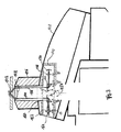
- FIG. 1 The schematic cross-sectional view of Figure 1 shows a conventional microscope in an inverted arrangement (Carl Zeiss Axiovert 100, 135, 135M, Carl Zeiss Jena).
- the main components are recognizable, namely a visual observation part 12 with eyepiece 14 at one end of the beam path and lens 16 at the other end and a plurality of interposed switched optical components within a passage 19 of a microscope housing 18th
- the beam path of a photographic observation part with camera 22 indicated in the outline can be coupled into the beam path.
- the beam path of a lighting part 24 can be coupled (via a partially transparent mirror 26 below a lens revolver head 28 carrying the lens 16 with turret axis of rotation 30).
- Adapter receptacle 32 is provided, the inclusion of adapters (DIC slider), in particular a Wollaston prism for observation of Objects in the differential interference contrast, is used.
- DI slider in particular a Wollaston prism for observation of Objects in the differential interference contrast
- the lens 16 is followed in FIG. 1 upwards in FIG. 1 omitted slide for the object to be microscoped. This is in the illustrated arrangement by the lighting part of pages illuminated by the observer (incident light arrangement). Will a fluoroscopy of the object desired, so one not shown in Figure 1 Lighting part for a corresponding illumination of the sample (in FIG 1 from above) at an aborted in Figure 1 shown above be arranged by the microscope 10 projecting carrier 34.
- FIG. 2 the region indicated by the circular area A in FIG. 1 is shown of the turret 28 shown enlarged including slide 36 and Object 38 on its upper side (side facing away from the lens 16 of the from a glass slide formed slide 36).
- an inventive adapter 40 instead of a inserted conventional adapter.
- This adapter 40 is thus without further conversion of the known microscope 10 can be used. He serves the Illumination of the object 38 according to the known principle of TIR (Total Internal Reflection) microscopy.
- the penetration depth of this field depends on the respective reflection angle ⁇ (which still meets the Totalreflexionsbedinung). Accordingly can be by changing the reflection angle ⁇ and the Lighting depth vary.
- an illumination beam which is strongly limited in cross section is used 44 used.
- the limitation is such that he is in the rear Focal plane 46 of the lens 16 substantially forms a point.
- that focal plane is meant that of the illumination beam 44 irradiated lens system of the lens 16 (in Figure 2 by a only front lens 48 indicated) corresponds. It could therefore be behind the Einkoppelstelle (prism 50) of the illumination beam 44 depending on the type of Lens 1 6 quite another lens or lens systems of the lens 16 (toward the eyepiece).
- Theoretically absolute parallelism of the partial beams after passing through the Front lens 48 of the lens is obtained when the illumination beam with the aid of corresponding optical elements (in FIG. 2 through a lens 52 indicated) in the rear (eyepiece) focal plane 46 is focused. It then arise after passing through the front lens 48 inevitably parallel partial beams of the illumination beam 44 with a common Reflection angle ⁇ corresponding to the distance a of the sub-beam 44 of the optical axis 54 of the objective 16.
- the degree of expansion of the illumination beam 44 after passage through the front lens 48 is through the Divergence angle ⁇ of the focused in the rear focal plane 46 illumination beam 44 determined.
- the aforementioned prism 50 is not dargestellen of one Illumination source (in Figure 2 left of the turret 28) coming from Illuminating beam deflected at right angles, so that it is parallel to the optical axis 54 and at a distance to this runs.
- the in the passage 19 located cross-section of the prism 50 is essential smaller than the total cross section of the passage 19. For this reason it is not necessary for the coupling of the illumination beam a Beam splitter, z.
- a dichroic mirror As a dichroic mirror to use, the one Transmission of the observation light coming from the object, because through the prism 50 only a small part of the field of observation of the microscope is obscured.
- the distance a can according to the invention in be particularly simple manner characterized in that the prism 50th either in the direction parallel to the optical axis 54, or as shown in the radial direction (double arrow B) is moved. With the distance a the angle of reflection ⁇ of the illumination beam 44 changes and thus After exceeding the total reflection angle, the penetration depth into the Object. Thus, even after the displacement of the prism 50 of the focus of Illuminating beam 44 is located in the focal plane 46, the need in the beam path provided optical components (symbolized by the lens 52) are adjusted accordingly in their position. If, as in Figure 2 the illumination beam is deflected at right angles, it is special advantageous, the deflection and the focusing serving optical To mount elements on a common support, since then only this carrier must be displaceable in the radial direction.
- the Beam cross section of the illumination beam 44 limited and thus on the Divergence angle ⁇ the degree of expansion of the illumination beam 44 after passing through the front lens 48 determines.
- the adapter 40 can be pulled out of the receptacle 32 again and possibly replaced by a conventional adapter. Further The adapter can also be used in conjunction with any other Lenses of the turret 28 are used, since usually Each lens is associated with a receptacle 32.
- an additional aperture diaphragm 62 in Figure 2 indicated below the prism 50 can be used. These Hides the prism 50 from the observation beam path and prevents possibly disturbing asymmetrical diffraction images (image distortions) the objects introduced by the in the illumination beam path Prism 50.
- the somewhat reduced numerical aperture and resolution can be accepted.
- a further variation of the type of illumination of the object 38 can thereby be achieved that the prism 50 together with the upstream optical components (lens 52) parallel to the optical axis 54 moves. Unless one is out of focus in the back focal plane 46 reaches, there is a certain divergence of the on the interface 42nd incident beam and a change in the degree of expansion.
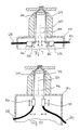
- FIG. 3 shows another embodiment of the adapter designated by 140 40 according to FIG. 2. Accordingly, the other components, if they have their equivalent in components of the adapter 40, with the same reference numerals, each increased by the number 100, provided.
- the adapter 140 In contrast to the adapter 40 with external light source is the adapter 140, the light source 164 integrated into the adapter 140. It closes the Lens 152 and the prism 150 at. After passing through the front lens 148 of the lens 116 and total reflection at the interface 142 is the Illumination beam 144 and the reflection beam 156 by another Prism 166 deflected by 90 ° (diametrically to the prism 150 together with the light source 164) and after passing through a lens 168 in a detector 170 collected.
- the detector 170 can be on the one hand, the optical Align arrangement specifically, especially the total reflection angle in Dependent on the position of the prism 150 and a desired one Range after exceeding the total reflection angle. on the other hand may be local refractive index changes, absorption processes or the like in the area of the interface 142. It is also, a wavelength variation of the light of the light source 164 conceivable.
- the adapter 140 can be selectively rotated about the optical axis 154.
- This offers the Advantage that for objects with anisotropic optical properties the Direction of irradiation of the observation beam 144 can be selectively varied can. You can also choose between rotation during the measurement obtain a uniform illumination of the object.
- FIGS. 4 and 5 show another side view and sectional view, respectively Embodiment of the adapter according to the invention, now with 240th is designated. Its components, which according to their function such 3 correspond to the same reference numerals, each increased by the number 100, provided.
- the reflection beam 256 is led out of the adapter 240 and fed to a detection device, not shown.
- the light source, not shown, is located (in correspondence to FIG. 2) outside of the adapter 240.
- the adjustment possibilities are the same as in the embodiment of Figure 3; which by the appropriate Double arrows D, D ', B, B' and E, E 'is indicated.
- the adapter 240 is between the lens 216 and the turret 228 arranged. He has on his side facing the lens one Port 290 on the lens mount 292 of the turret 228, in which normally the lens 216 is fitted, corresponds. On its turret 228 side facing the adapter 240 has a terminal 286 which is the eyepiece-side terminal 288 of Lens 216, which is normally in the lens mount 292 of the turret 228 is fitted, corresponds. In this way, the Adapter 240 easily integrated into an existing microscope without having to rebuild it.
- the two prisms 250, 266 have rounded reflection surfaces, to minimize the microscopic observation (see Figure 5). Furthermore, in the adapter 240 is on the object 238 facing away from the prisms 250, 266 a filter wheel 272 with axis of rotation 274 arranged in the observation beam path. It can be done with it For example, those portions of the illumination beam 244 that are not considered Reflection beam 256 are coupled out of the adapter 240 again (in particular diffusely scattered portions), from the observation beam path filter out. This is especially true for fluorescence measurements of Advantage.
- FIG. 6 of the adapter according to the invention is designated 340. He is different from the one according to the Figures 4 and 5 only in that the prisms 250, 266 are replaced by plane mirrors 350, 366. By displacing the mirror 350 in FIG Direction perpendicular to the optical axis 354 (while maintaining the Spatial orientation), the total reflection angle can be in the same way as change when using a prism
- the two planar mirrors 350, 366 according to FIG. 6 are replaced by curved mirrors, in particular concave mirrors 450, 466.
- the coupling and focusing of the illumination beam 440 may then occur without further optical elements such as an upstream lens accordingly the embodiments described above.
- the beam guidance of the reflection beam 456 takes place symmetrically through the mirror 466.
- FIG. 8 shows in a greatly simplified perspective schematic view a deflection device 576, which is used to couple a plurality of illumination beams 544, 544 ', 544' ', 544' '' and for decoupling the corresponding Reflection rays 556, 556 ', 556' ', 556' '' is used.
- the deflection device 576 consists of concentrically arranged, annularly connected deflecting elements, which in FIG. 8 are trapezoidal Mirrors 550, 550 ', 550' ', 550' '', 566, 566 ', 566' ', 566 ''are shown.
- an illumination beam, z. B. the one provided with the reference numeral 544, on the respective deflecting element, z. B. 550, reflected so that it parallel to after reflection optical axis 554 and passes through the lens 548 on the slide 536 is mapped to the object 538.
- the one at the interface between object stage 536 and object 538 totally reflected illumination beam, z. B.
- each of the illumination beams 544 - 544 '' ' satisfies in the same way the total reflection condition.
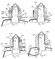
- FIGS 9 and 10 are further embodiments of the already in the Figures 2-7 shown adapter shown as a side view.
- the components this adapter designated by the reference numerals 640 and 740, whose function corresponds to that of the adapter shown in FIG. 4, are numbered the same but increased by 400 or 500 provided.
- Adapters 640 and 740 will illuminate the illumination light via a light guide 678 or 778, for example, a glass fiber, in the adapter 640 or 740 introduced.
- the light guide 678 or 778 includes a, z. B. made of microlenses, adapter optics 680 or 780 on to the off the light guide 678 or 778 exiting illumination beam 644 or 744 in the back focal plane 646 and 746, respectively.
- the light guide 678 is perpendicular to the optical axis 654 inserted into the adapter 640 so that he via a deflection unit, which is shown in FIG. 9 as a prism 650, in FIG a direction parallel to the optical axis 654 has to be deflected.
- the optical fiber 778 is as shown in FIG Curved embodiment, so that the adapter optics 780 leaving Focused illumination beam 744 already parallel to the optical Axis 754 is.
- a coupling of the reflection beam 656 and 756 with the help of optical elements, the Coupling used correspond to done.
- this is through the prism 666 and the light guide 682, via the adapter optics 684 with connected to the prism 666 realized.
- this is done by the Optical fiber 782 and mounted at its end adapter optics 784, the with respect to the optical axis 754 symmetrical to that for coupling of the illumination beam 744 used adapter optics 780 is.
- FIGS. 11-14 illustrate embodiments of the present invention the deflection units, which are used to couple the illumination beam or for decoupling the reflection beam serve, in a special Lens 816, 916, 1016, 1116 are intregiert. Components that are theirs Function according to those shown in the preceding figures, are in Figures 11-14 with the same reference numerals, however each increased by the number 100, respectively. Compared to the statements, where the baffle units are integrated in an adapter, offer the In the embodiments illustrated in FIGS. 11-14, the advantage that the for the deflection units require optical components to the lens system of the Lens 816, 916, 1016, 1116 can be adjusted, thereby Overall, the quality of the optical image can be optimized. In addition, such special lenses can also be used for microscopes which do not have an adapter receptacle as in FIG. 2 have shown.
- the illumination beam 844 is transmitted via a bar prism 850 in FIG coupled to the beam path of the microscope.
- the reflection beam 856 via a further bar prism 866 from the lens 816 led out.
- both prisms 850, 866 are in the range of the objective arranged so that they adjust the reflection angle in the Beam path of the microscope in the radial direction are displaced (shown by the double arrows B, B 'in FIG. 11).
- An alternative arrangement of the rod prism 850 is indicated by dashed lines in FIG. In this arrangement is the rod prism 850 'for coupling the illumination beam 844 between the irradiated front lens of the lens and its eyepiece focal plane 846.
- the illumination beam 844 is in In this case, virtually irradiated on the eyepiece focal plane 846 of the Lensensystems focused. This arrangement allows a particularly space saving construction of a special lens with integrated deflection unit.
- optical fibers 1078, 1082, 1178 are used to avoid that of one depict light source coming illumination light in the area of the lens couple into the beam path of the microscope or decouple.
- FIG. 13 which is similar to that in FIG. 9, becomes an attached to the light guide 1078 adapter optics 1080 and a to the adapter optics 1080 adjoining prism 1050 for coupling of the illumination beam 1044.
- the decoupling of the Reflection beam 1056 is made by a with respect to the optical axis 1054 symmetrically arranged prism 1066 and an adjoining Adapter optics 1084, to which a light guide 1082 is coupled.
- Figure 14 an embodiment is shown in Figure 14, in which a curved light guide 1178 with an adapter optics 1180 parallel to optical axis 1154 is connected to the illumination beam 1144 parallel to the optical axis in the beam path of Coupling microscope.
- FIGS. 1 to 14 show different embodiments of a Microscope described which is used in particular for TIR microscopy can be.
- the microscope is in a Auflichtan angel operated, in which the serving for the illumination of the object light through at least part of the objective falls on the object to be observed.
- the illumination beam by an optical device in the Passage between the eyepiece and the lens of the microscope coupled, their lying in the passage cross-section small opposite is the cross section of the passage.
- beam splitter elements eg.
- dichroic mirrors Coupling of the illumination light can be dispensed with.
- It can be one Special lens with integrated optical elements to provide the Illumination beam or for collecting or decoupling the reflection beam be used.
- the mentioned optical Elements can also be integrated into an adapter that is in the beam path an existing microscope can be used.
Landscapes
- Physics & Mathematics (AREA)
- General Physics & Mathematics (AREA)
- Optics & Photonics (AREA)
- Chemical & Material Sciences (AREA)
- Analytical Chemistry (AREA)
- Engineering & Computer Science (AREA)
- Multimedia (AREA)
- Computer Vision & Pattern Recognition (AREA)
- Microscoopes, Condenser (AREA)
- Analysing Materials By The Use Of Radiation (AREA)
Applications Claiming Priority (3)
| Application Number | Priority Date | Filing Date | Title |
|---|---|---|---|
| DE10143481 | 2001-09-05 | ||
| DE10143481A DE10143481A1 (de) | 2001-09-05 | 2001-09-05 | Mikroskop |
| EP02776983A EP1423746B1 (fr) | 2001-09-05 | 2002-09-04 | Microscope |
Related Parent Applications (1)
| Application Number | Title | Priority Date | Filing Date |
|---|---|---|---|
| EP02776983A Division EP1423746B1 (fr) | 2001-09-05 | 2002-09-04 | Microscope |
Publications (2)
| Publication Number | Publication Date |
|---|---|
| EP1557708A2 true EP1557708A2 (fr) | 2005-07-27 |
| EP1557708A3 EP1557708A3 (fr) | 2005-08-10 |
Family
ID=7697782
Family Applications (2)
| Application Number | Title | Priority Date | Filing Date |
|---|---|---|---|
| EP05008916A Withdrawn EP1557708A3 (fr) | 2001-09-05 | 2002-09-04 | Microscope avec illumination évanescent |
| EP02776983A Expired - Lifetime EP1423746B1 (fr) | 2001-09-05 | 2002-09-04 | Microscope |
Family Applications After (1)
| Application Number | Title | Priority Date | Filing Date |
|---|---|---|---|
| EP02776983A Expired - Lifetime EP1423746B1 (fr) | 2001-09-05 | 2002-09-04 | Microscope |
Country Status (7)
| Country | Link |
|---|---|
| US (1) | US6987609B2 (fr) |
| EP (2) | EP1557708A3 (fr) |
| AT (1) | ATE298097T1 (fr) |
| AU (1) | AU2002339487A1 (fr) |
| CA (1) | CA2459363A1 (fr) |
| DE (2) | DE10143481A1 (fr) |
| WO (1) | WO2003023483A2 (fr) |
Cited By (1)
| Publication number | Priority date | Publication date | Assignee | Title |
|---|---|---|---|---|
| DE102017109645A1 (de) * | 2017-05-05 | 2018-11-08 | Carl Zeiss Microscopy Gmbh | Lichtmikroskop und Verfahren zum Bereitstellen von strukturiertem Beleuchtungslicht |
Families Citing this family (32)
| Publication number | Priority date | Publication date | Assignee | Title |
|---|---|---|---|---|
| DE10309269B4 (de) * | 2003-03-03 | 2005-06-02 | Till Photonics Gmbh | Vorrichtung für Totale Interne Reflexions-Mikroskopie |
| WO2005029149A1 (fr) | 2003-09-25 | 2005-03-31 | Leica Microsystems Cms Gmbh | Microscope a eclairage evanescent |
| EP1678545B1 (fr) | 2003-09-25 | 2009-04-01 | Leica Microsystems CMS GmbH | Microscope a eclairage evanescent de l'echantillon |
| EP1678544A1 (fr) * | 2003-09-25 | 2006-07-12 | Leica Microsystems CMS GmbH | Procede d'examen d'echantillon et microscope a eclairage evanescent de l'echantillon |
| US7808699B2 (en) | 2003-09-25 | 2010-10-05 | Leica Microsystems Cms Gmbh | Microscope lens for total internal reflection microscopy and microscope |
| DE502004008954D1 (de) * | 2003-09-25 | 2009-03-19 | Leica Microsystems | Mikroskop mit evaneszenter beleuchtung |
| EP1668395A1 (fr) | 2003-09-25 | 2006-06-14 | Leica Microsystems Heidelberg GmbH | Objectif pour eclairage evanescent et microscope |
| DE502004008431D1 (de) * | 2003-09-25 | 2008-12-18 | Leica Microsystems | Beleuchtungsmodul zur evaneszenten beleuchtung und mikroskop |
| DE10344410A1 (de) * | 2003-09-25 | 2005-04-28 | Leica Microsystems | Rastermikroskop mit evaneszenter Beleuchtung |
| US7369308B2 (en) * | 2004-02-09 | 2008-05-06 | Olympus Corporation | Total internal reflection fluorescence microscope |
| US20060012793A1 (en) * | 2004-07-19 | 2006-01-19 | Helicos Biosciences Corporation | Apparatus and methods for analyzing samples |
| US7276720B2 (en) | 2004-07-19 | 2007-10-02 | Helicos Biosciences Corporation | Apparatus and methods for analyzing samples |
| GB0424652D0 (en) * | 2004-11-08 | 2004-12-08 | Imp College Innovations Ltd | Fluorescence polarisation in TIRF |
| US7486441B2 (en) | 2005-03-01 | 2009-02-03 | Leica Microsystems Cms Gmbh | Objective and microscope |
| DE102005009832A1 (de) | 2005-03-01 | 2006-09-07 | Leica Microsystems Cms Gmbh | Objektiv und Mikroskop |
| DE102005011979B4 (de) * | 2005-03-14 | 2010-05-12 | Leica Microsystems Cms Gmbh | Mikroskop |
| DE102005023768B4 (de) * | 2005-05-19 | 2017-06-29 | Leica Microsystems Cms Gmbh | Verfahren zur Ermittlung der Orientierung von Molekülen in biologischen Proben |
| DE102005037818A1 (de) | 2005-08-08 | 2007-02-15 | Leica Microsystems Cms Gmbh | Mikroskop |
| DE102006021996B4 (de) * | 2005-08-12 | 2016-09-01 | Leica Microsystems Cms Gmbh | Mikroskop und Verfahren zur Totalinternen Reflexions-Mikroskopie |
| WO2007019906A1 (fr) * | 2005-08-12 | 2007-02-22 | Leica Microsystems Cms Gmbh | Microscope et procede de microscopie a reflexion interne totale |
| DE102005048555A1 (de) | 2005-10-06 | 2007-04-12 | Carl Zeiss Jena Gmbh | Verfahren zur Justierung einer Lichtquelle in einem Mikroskop |
| EP1941313B1 (fr) * | 2005-10-27 | 2014-12-03 | Yale University | Optique d'eclairage de champ evanescent |
| DE102007018922A1 (de) | 2007-02-12 | 2008-08-14 | Leica Microsystems Cms Gmbh | Mikroskop |
| DE102007007395A1 (de) | 2007-02-12 | 2008-08-14 | Leica Microsystems Cms Gmbh | Mikroskop |
| US8537461B2 (en) * | 2007-11-26 | 2013-09-17 | Carl Zeiss Microimaging Gmbh | Method and configuration for the optical detection of an illuminated specimen |
| DE102008012585A1 (de) * | 2008-03-05 | 2009-09-24 | Carl Zeiss Microlmaging Gmbh | Objektivwechsler mit Auflichtbeleuchtung für Lichtmikroskope |
| DE102010034122B4 (de) | 2010-08-12 | 2020-03-26 | Carl Zeiss Microscopy Gmbh | Mikroskop und Objektiv, insbesondere für die TIRF-Mikroskopie |
| GB201215771D0 (en) * | 2012-09-04 | 2012-10-17 | Univ Nottingham | Monitoring and/or characterising biological or chemicl material |
| US9500847B2 (en) | 2012-10-12 | 2016-11-22 | Spectral Applied Research Inc. | Total internal reflectance fluorescence (TIRF) microscopy across multiple wavelengths simultaneously |
| DE102013112600A1 (de) * | 2013-11-15 | 2015-05-21 | Carl Zeiss Microscopy Gmbh | Optisches Übertragungssystem und Mikroskop mit einem solchen Übertragungssystem |
| LU92505B1 (de) * | 2014-07-22 | 2016-01-25 | Leica Microsystems | Verfahren und vorrichtung zum mikroskopischen untersuchen einer probe |
| EP3963380A4 (fr) * | 2019-05-01 | 2023-01-25 | The University of Melbourne | Appareil et procédé de microscopie d'imagerie par résonance de champ évanescent |
Family Cites Families (12)
| Publication number | Priority date | Publication date | Assignee | Title |
|---|---|---|---|---|
| JPH0720652Y2 (ja) * | 1986-03-31 | 1995-05-15 | 株式会社トプコン | 手術用顕微鏡 |
| DE4028605C2 (de) * | 1990-09-08 | 1997-09-04 | Zeiss Carl Fa | Beleuchtungseinrichtung für ein Operationsmikroskop |
| DE4243144B4 (de) | 1992-12-19 | 2008-08-21 | BRUKER OPTICS, Inc., Billerica | Objektiv für ein FT-Raman-Mikroskop |
| JP3497244B2 (ja) * | 1994-07-06 | 2004-02-16 | オリンパス株式会社 | 近接場光走査型顕微鏡 |
| JP3872871B2 (ja) * | 1996-07-29 | 2007-01-24 | オリンパス株式会社 | 対物レンズ及び顕微鏡 |
| JPH1096862A (ja) * | 1996-09-20 | 1998-04-14 | Bunshi Bio Photonics Kenkyusho:Kk | 落射蛍光顕微鏡装置 |
| JP3861357B2 (ja) * | 1997-03-10 | 2006-12-20 | 株式会社ニコン | 光学装置と一体化された顕微鏡用レボルバおよび顕微鏡 |
| DE19842153C2 (de) * | 1998-09-15 | 2003-07-31 | Leica Microsystems | Fluoreszenzmikroskop |
| WO2000050878A1 (fr) | 1999-02-26 | 2000-08-31 | Gsi Lumonics, Inc. | Systeme d'imagerie pour un scanner |
| EP1109046B1 (fr) | 1999-12-15 | 2002-09-25 | Möller-Wedel GmbH | Dispositif d'éclairage pour un microscope opératoire |
| US6597499B2 (en) * | 2001-01-25 | 2003-07-22 | Olympus Optical Co., Ltd. | Total internal reflection fluorescence microscope having a conventional white-light source |
| US6819484B2 (en) * | 2001-11-06 | 2004-11-16 | Olympus Optical Co., Ltd. | Total internal reflection illumination apparatus and microscope using this total internal reflection illumination apparatus |
-
2001
- 2001-09-05 DE DE10143481A patent/DE10143481A1/de not_active Withdrawn
-
2002
- 2002-09-04 AT AT02776983T patent/ATE298097T1/de not_active IP Right Cessation
- 2002-09-04 WO PCT/EP2002/009901 patent/WO2003023483A2/fr not_active Ceased
- 2002-09-04 EP EP05008916A patent/EP1557708A3/fr not_active Withdrawn
- 2002-09-04 US US10/488,769 patent/US6987609B2/en not_active Expired - Fee Related
- 2002-09-04 DE DE50203427T patent/DE50203427D1/de not_active Expired - Lifetime
- 2002-09-04 EP EP02776983A patent/EP1423746B1/fr not_active Expired - Lifetime
- 2002-09-04 AU AU2002339487A patent/AU2002339487A1/en not_active Abandoned
- 2002-09-04 CA CA002459363A patent/CA2459363A1/fr not_active Abandoned
Cited By (2)
| Publication number | Priority date | Publication date | Assignee | Title |
|---|---|---|---|---|
| DE102017109645A1 (de) * | 2017-05-05 | 2018-11-08 | Carl Zeiss Microscopy Gmbh | Lichtmikroskop und Verfahren zum Bereitstellen von strukturiertem Beleuchtungslicht |
| US11454792B2 (en) | 2017-05-05 | 2022-09-27 | Carl Zeiss Microscopy Gmbh | Light microscope and method for providing structured illumination light |
Also Published As
| Publication number | Publication date |
|---|---|
| WO2003023483A2 (fr) | 2003-03-20 |
| EP1423746A2 (fr) | 2004-06-02 |
| EP1557708A3 (fr) | 2005-08-10 |
| US20040240046A1 (en) | 2004-12-02 |
| ATE298097T1 (de) | 2005-07-15 |
| DE10143481A1 (de) | 2003-03-20 |
| DE50203427D1 (de) | 2005-07-21 |
| AU2002339487A1 (en) | 2003-03-24 |
| CA2459363A1 (fr) | 2003-03-20 |
| WO2003023483A3 (fr) | 2003-10-16 |
| US6987609B2 (en) | 2006-01-17 |
| EP1423746B1 (fr) | 2005-06-15 |
Similar Documents
| Publication | Publication Date | Title |
|---|---|---|
| EP1423746B1 (fr) | Microscope | |
| DE3442218C2 (fr) | ||
| DE19629725C2 (de) | Doppelobjektiv-System für ein Mikroskop, insbesondere Rastermikroskop | |
| DE10027167B4 (de) | Mikroskop mit einem Beleuchtungssystem | |
| DE10309269B4 (de) | Vorrichtung für Totale Interne Reflexions-Mikroskopie | |
| EP3132299B1 (fr) | Microscope à balayage lumineux avec optique simplifiée, en particulier avec position de pupille modifiable | |
| EP0859968B1 (fr) | Unite de deviation de faisceau pour examen sur plusieurs axes dans un microscope | |
| DE19803106A1 (de) | Konfokales Mikrospektrometer-System | |
| EP2185953B1 (fr) | Piège à lumière, dispositif de couplage pour une trajectoire de faisceau ainsi que dispositif d'éclairage et dispositif d'observation optique | |
| DE102014017002A1 (de) | Laser-Scanning-Mikroskop | |
| EP0908709A2 (fr) | Dispositif de mesure sans contact de vibrations | |
| DE10120424B4 (de) | Scanmikroskop und Auskoppelelement | |
| EP1460466A1 (fr) | Microsocope, notamment microscope stéréoscopique | |
| EP1697781B1 (fr) | Microscope avec eclairage evanescent | |
| DE3853475T2 (de) | Konzept und umwandlungssatz eines standardmikroskops in ein mikroskop mit gemeinsamem brennpunkt und epi-beleuchtung mit einzelöffnung. | |
| DE102014118025B4 (de) | Vorrichtung zur Lichtblattmikroskopie | |
| EP1985227B1 (fr) | Composant optique pour un microscope stéreoscopique | |
| EP1168031A2 (fr) | Structure de microscope | |
| DE10021379A1 (de) | Optische Messanordnung insbesondere zur Schichtdickenmessung | |
| DE10135321B4 (de) | Mikroskop und Verfahren zur Untersuchung einer Probe mit einem Mikroskop | |
| CH469480A (de) | Spaltlampengerät für Augenuntersuchungen | |
| EP2784564A1 (fr) | Microscope lumineux et procédé d'analyse d'un échantillon microscopique | |
| DE4005878C2 (fr) | ||
| DE102014108596B3 (de) | Objektiv und optisches Gerät | |
| DE255788C (fr) |
Legal Events
| Date | Code | Title | Description |
|---|---|---|---|
| PUAI | Public reference made under article 153(3) epc to a published international application that has entered the european phase |
Free format text: ORIGINAL CODE: 0009012 |
|
| PUAL | Search report despatched |
Free format text: ORIGINAL CODE: 0009013 |
|
| 17P | Request for examination filed |
Effective date: 20050422 |
|
| AC | Divisional application: reference to earlier application |
Ref document number: 1423746 Country of ref document: EP Kind code of ref document: P |
|
| AK | Designated contracting states |
Kind code of ref document: A2 Designated state(s): AT BE BG CH CY CZ DE DK EE ES FI FR GB GR IE IT LI LU MC NL PT SE SK TR |
|
| AK | Designated contracting states |
Kind code of ref document: A3 Designated state(s): AT BE BG CH CY CZ DE DK EE ES FI FR GB GR IE IT LI LU MC NL PT SE SK TR |
|
| AKX | Designation fees paid |
Designated state(s): AT BE BG CH CY CZ DE DK EE ES FI FR GB GR IE IT LI LU MC NL PT SE SK TR |
|
| STAA | Information on the status of an ep patent application or granted ep patent |
Free format text: STATUS: THE APPLICATION IS DEEMED TO BE WITHDRAWN |
|
| 18D | Application deemed to be withdrawn |
Effective date: 20060530 |