EP1557795B1 - Procedé de conception des images à deux dimensions à utiliser sur des cartons tridimensionnels - Google Patents
Procedé de conception des images à deux dimensions à utiliser sur des cartons tridimensionnels Download PDFInfo
- Publication number
- EP1557795B1 EP1557795B1 EP05075126.2A EP05075126A EP1557795B1 EP 1557795 B1 EP1557795 B1 EP 1557795B1 EP 05075126 A EP05075126 A EP 05075126A EP 1557795 B1 EP1557795 B1 EP 1557795B1
- Authority
- EP
- European Patent Office
- Prior art keywords
- graphics
- carton
- computer
- regions
- printed
- Prior art date
- Legal status (The legal status is an assumption and is not a legal conclusion. Google has not performed a legal analysis and makes no representation as to the accuracy of the status listed.)
- Expired - Lifetime
Links
Images




Classifications
-
- G—PHYSICS
- G06—COMPUTING OR CALCULATING; COUNTING
- G06K—GRAPHICAL DATA READING; PRESENTATION OF DATA; RECORD CARRIERS; HANDLING RECORD CARRIERS
- G06K15/00—Arrangements for producing a permanent visual presentation of the output data, e.g. computer output printers
- G06K15/02—Arrangements for producing a permanent visual presentation of the output data, e.g. computer output printers using printers
-
- G—PHYSICS
- G06—COMPUTING OR CALCULATING; COUNTING
- G06F—ELECTRIC DIGITAL DATA PROCESSING
- G06F30/00—Computer-aided design [CAD]
-
- G—PHYSICS
- G06—COMPUTING OR CALCULATING; COUNTING
- G06T—IMAGE DATA PROCESSING OR GENERATION, IN GENERAL
- G06T19/00—Manipulating three-dimensional [3D] models or images for computer graphics
-
- G—PHYSICS
- G06—COMPUTING OR CALCULATING; COUNTING
- G06F—ELECTRIC DIGITAL DATA PROCESSING
- G06F2113/00—Details relating to the application field
- G06F2113/20—Packaging, e.g. boxes or containers
-
- G—PHYSICS
- G06—COMPUTING OR CALCULATING; COUNTING
- G06T—IMAGE DATA PROCESSING OR GENERATION, IN GENERAL
- G06T2219/00—Indexing scheme for manipulating 3D models or images for computer graphics
- G06T2219/021—Flattening
Definitions
- the present invention relates generally to computerized design of two-dimensional graphics for use on three-dimensional objects such as containers, cartons, boxes, and the like, and more specifically to computerized graphic design to facilitate proper alignment and sizing of graphics printed on a substrate from which two-dimensional flaps and panels are cut and folded to form a three-dimensional container bearing the graphics.
- Containers, cartons, boxes, and the like are commonly formed from a planar substrate such as corrugated cardboard, although other material may be used.
- the substrate is often printed with graphics, scored, and then folded at scored edges through a typically 90° fold angle to form a three-dimensional carton.
- the various planes of the carton e.g., top, bottom, sides, are often referred to as panels, and a panel may be formed from, or include, several flaps.
- a side of a carton that comprises a single panel without flaps may also be termed a carton surface.
- FIG. 1 depicts the above nomenclature for an exemplary container or carton 10.
- Carton 10 is formed from a sheet or roll of substrate material 20 that is scored, cut, (or cut and then scored), and folded generally at scored fold edges 30 through a fold angle ⁇ to define various carton panels. Fold angle ⁇ is typically 90°, where 0° is defined as being in the plane of the unfolded material.
- Carton 10 is shown with upper and lower panels 40, 50, front and rear panels 60, 70, and left and right panels 80 and 90.
- Front panel 60 is shown as comprising a single panel and thus may also be referred to as carton surface 60. In the example shown in FIG.
- upper panel 40 is formed from two half-flaps 40A and 40B, and right panel 90 is formed from no less than five flaps 90A, 90B, 90C, 90D, and 90E. It is understood that panels may, but need not be, formed from flaps.
- the outer panel surfaces of cartons frequently will have been printed with graphic designs that can advertise the product within and convey other useful information.
- the printed design may be graphics per se, text, or other indicia (collectively referred to herein as graphics).
- graphics graphics per se, text, or other indicia
- a graphics artist typically will design the graphics for carton 10 on a panel-by-panel basis. Such design is undertaken without the graphics artist having knowledge of how the carton is folded, or even how some of the panels may be formed from individual flaps, or portions of flaps.
- the graphics for upper panel 40 may be rendered as a first electronic file, created on a computer using a software drawing program, the graphics for front and rear panels 60 and 70 may be rendered as second and third electronic files.
- the graphics for right panel 90 may be rendered as yet another electronic file.
- the flaps that comprise a panel may themselves be created as separate electronic files.
- the graphics depicted on right panel 90 may be generated from as many as five separate electronic files, one file for each of flaps 90A, ... 90E. While the various panel files may be combined into a single file, the point to be made is that the graphics are generally created on a per-panel or per-flap basis, almost as though separate graphics design projects were being undertaken.
- the graphics artist In creating the various electronic files, the graphics artist generally is concerned only with the dimensions of the various substrate areas of interest, e.g., the overall size of the individual panels and flaps to be printed. How the substrate will be folded to form a carton is generally the responsibility of a structural designer and too often may be of little concern to the graphics artist. Indeed, the graphics artist typically is more concerned with how the printed graphics will look on individual panels or on the finished product - a three-dimensional carton, than how the graphics needs to be laid out on the different flaps.
- Computerized tools are known in the art to aid in the structural design of the carton by embedding folding information in the structural design, and to allow the graphical designer to take a flat or planar layout and, using folding information, view the design on a computer monitor in a rendered three-dimensional form.
- US Patent No 6 117 061 discloses a method for forming custom-printed three dimensional structures using a computer.
- the method uses one or more rectangular sheets with a particular size and which are pre-perforated to form a removable portion.
- a user instructs a computer program to command a computer-controlled printer to print particular information onto the printing surface of the removable portion.
- What is needed is a computerized method by which panel folding sequence and other carton structural information can be embedded into a structural design file for use by a graphics artist.
- Such carton structural information should enable a graphics artist to use a software tool to display the carton in a planar, unfolded, layout state, and to design and superimpose graphics upon the substrate areas to be printed on an actual carton.
- a computerized method should automatically position and manipulate the graphics as required to properly appear on the flaps comprising the panel. For graphics appearing on panels that are made up of different flaps, the computerized method will copy and position the graphics onto the different corresponding substrate areas.
- Such information and software tool should enable the graphics artist to create and view on a computer monitor a three-dimensional image of the completed carton.
- a computerized method will enable the artist to rotate, scale, copy, "cut” or “paste” portions of graphics on the various panels and flaps, and to generate clipping masks as needed.
- the graphics artist should be able to manipulate such computer-generated three-dimensional image to visually confirm that proper registration and layout of graphics will indeed occur for each panel and flap in producing printed cartons, and to make changes to the proposed graphics, as necessary.
- the present invention provides such a computerized method, and provides cartons bearing graphics that are designed and laid out according to such method.
- Planar substrates from which panels and flaps are defined, cut, and folded to form a three-dimensional carton are first printed with graphics laid-out with a computerized graphics program that permits construction of a three-dimensional model of the carton showing the graphics to be printed.
- the graphics program is provided with carton structural input information including dimensions of the various panels and flaps, fold or score lines, and fold angles, which information is available from the carton structural designer. Given the graphics to be printed on a panel of a finished carton, even a panel that is comprised of several flaps, aspects of the invention automatically position and manipulate the graphics using available carton structural information. The desired result is that portions of the graphics will be printed on the panel and flaps comprising a panel such that when the carton is formed the graphics appear as desired.
- the graphics program Preferably the graphics program generates a single computer file containing graphics for each panel and flap of the carton to be created from the substrate material.
- the graphics program creates for display and manipulation on a computer monitor both planar and three-dimensional images of the carton, including the carton with graphics. While viewing such display, the graphics designer can rotate, scale, and otherwise manipulate the displayed graphics, as needed, to accommodate each panel and flap, and preferably can define clipping masks as needed.
- the ability to view and manipulate a three-dimensional computer-generated image of a virtual carton whose panels and flaps contain the graphics allows the graphics artist to confirm proper alignment, orientation, and scaling of graphics on the finished carton.
- the computer-generated file is output and made available as input to a carton production system to control printing of graphics on the flat substrate before the substrate is cut and folded to yield the three-dimensional carton bearing the printed graphics.
- Object of the present invention is a computer-implemented method of designing graphics to be printed on a planar substrate that will be cut and folded to yield a three-dimensional carton having outer surface regions that will be printed with the graphics so designed.
- the method comprising the steps of:
- the structural information includes at least one of:
- the method can further include identifying regions of graphics to be printed on said carton that are likely to experience printing ink bleeding and compensating for such bleeding in laying out said regions of said graphics.
- Manipulating at step (c) above can include at least one of (i) rotation, (ii) scaling, (iii) copying, (iv) cutting, and (v) pasting.
- the method preferably further includes providing said computer- readable file output as input to a carton fabrication system.
- the system for the design of graphics to be printed on a planar substrate can include a carton fabrication system to which said computer-readable file output from said computer system is input to control at least printing of cartons within said carton fabrication system.
- the carton fabrication system provides printing of said substrate with graphics before said substrate is cut.
- the carton fabrication system includes identifying regions of graphics to be printed on said carton that are likely to experience printing ink bleeding and compensating for such bleeding in laying out said regions of said graphics.
- a further object of the invention consists in a computer-readable medium storing a software program that when executed by a computer processor will carry out the steps of the computer-implemented method above in order to assist in the design of graphics to be printed on a planar substrate that will be cut and folded to yield a three-dimensional carton regions of whose outer surface will be printed with the graphics.
- FIG. 2 is a flow chart depicting a computerized method by which two-dimensional graphics can be accurately created for printing on a substrate from which panels and flaps will be cut and folded to form a three dimensional carton. Implementation of the method shown achieves good alignment and registration of the overall graphics on the completed three-dimensional carton, with reduced labor and reduced likelihood of human error.
- structural information relating to the physical characteristics of the carton to be fabricated is preferably input to a computer-executable set of instructions. Such information will typically already be available to the structural designer of the carton. Preferably this information includes parameters such as the overall length, width, depth dimensions of the carton, the area and orientation of each surface, panel, and flap, the folding or score lines and fold angles associated with the panels and flaps. Other structural information can include thickness and composition of the substrate, including ease of folding information.
- a graphics artist is given or creates the graphics intended to appear on a surface or overall panel of a completed carton.
- the overall graphics for a surface or panel will be represented as graphics designed for each surface or panel for the carton that is to bear printing.
- Such design preferably is executed on a computer system (e.g., system 210 in FIG. 3 , described later herein) using design software whose input data includes the structural information provided at step 100 in FIG. 2 .
- the graphics artist preferably views a computer generated image that depicts a planar (unfolded) substrate and indicates where cut lines and scoring or fold lines will be defined.
- the graphics artist can view the display on the computer monitor and superimpose the computer-generated graphics over monitor-displayed various panels of the carton.
- Superimposing graphics on the panels involves positioning the graphics on all the flaps that contribute to this panel using information provided at step 100.
- the graphics artist can, at step 130, manipulate (e.g., stretch, shrink, rotate, invert, copy, cut, and paste) portions of the graphics over the outline of the substrate until satisfied that properly proportioned graphics cover the panel and flap regions intended to bear printed graphics.
- clipping masks can now be defined. Such masks can avoid printing on regions of substrate material that will ultimately be covered as the result of a folded-over overlying region of panel or flap material. Printing resources can thus be conserved, print bleeding can be minimized and glue results can be optimized.
- Method step 150 allows the graphics artist to visually confirm the accuracy of the design by generating three-dimensional computer images of the final carton showing how the printed graphics will actually appear.
- the graphic artist can manipulate (e.g., rotate, resize, etc.) the computer displayed image of the carton to view the various panels and flaps.
- such virtual viewing allows the designer to confirm proper graphic alignment, especially where adjacent portions of panels and/or flaps bear a sub-portion of an overall image that should appear in good alignment on the carton surface.
- the graphics artist will, in method step 160, create a computer-generated output graphics file. This output file can then be provided as graphics input to a system or portions of a system used to print and then fabricate the desired cartons.
- FIG. 3 depicts system components that can be used to carry out the above-described methodology.
- a graphics creation system 200 preferably includes a computer system 210 that includes a CPU 220 and memory that typically includes persistent memory 230 and non-persistent memory 240.
- Stored or loadable into memory 230 is a software program 250 that when executed by CPU 220 will cause the methodology of an aspect of the present invention to be carried out.
- program 250 may be stored on external media 230', perhaps optical or magnetic storage, to be read into computer system 210.
- the storage media 230' may in fact be physically remote from computer system 210, and may, if desired, be accessed over a communications link such as the Internet, a network, etc.
- Computer system 210 also receives as input structural information pertaining to the carton to be generated, for example information described with respect to method step 100 in FIG. 2 .
- CPU 220 executes program 250
- the graphics artist can create and then layout the various images and/or text for panel and flap areas of the carton in question.
- Commercially available graphic design software is known in the art and may be used as part of program 250 at this juncture, or dedicated software 250 may be used.
- Exemplary such commercially available software includes PackEdge, manufactured by Esko-Graphics located in Ghent/Belgium.
- the graphics artist will use one or more input devices such as a mouse, a trackball, a joystick, a digitizer tablet, and even a computer keyboard to create such images, and/or to load images from memory 230 and/or 230'.
- input devices such as a mouse, a trackball, a joystick, a digitizer tablet, and even a computer keyboard to create such images, and/or to load images from memory 230 and/or 230'.
- a vast quantity of images is available, for example, from commercial vendors, and can be downloaded from numerous websites via the Internet.
- the graphics artist can view on computer monitor 2 60 a display 270 of the i mages being created and/or manipulated. As noted with respect to method steps 110, 120, and 130 in FIG. 2 , the graphics artist can superimpose on display 270 the created (and/or downloaded) graphics upon a planar outline of the carton. ( FIG. 5 depicts an exemplary such image.)
- Program 250 uses the structural information to copy and position the images on the various flaps that contribute to the panel being worked on. This superimposition allows the artist to confirm that the relevant panels and flaps appear to be covered with properly sized and oriented images.
- the structural information available to program 250 includes folding details and characteristics of the substrate, the artist can readily determine areas of panels and flaps that need not be printed at all because they are covered by portions of other panels or flaps.
- appropriate clipping masks can be generated by program 250 such that covered-over substrate portions are not needlessly printed with graphics. Further, appropriate clipping masks can reduce degradation of the printed imagery. In addition, the effects of ink bleeding into the substrate and into adjacent regions of the graphics are also reduced.
- the graphics artist can now cause program 250 to create a three-dimensional image of the carton replete with printed graphics.
- Two such images 10' are shown as being displayed by monitor 260.
- image 10' In the left-hand image 10', one of the side flaps is not yet folded, whereas in the right-hand portion of the display, the side flap has been folded through a 90° fold angle, and image 10' has been rotated to permit an end-on view of the side flap and the composite image printed on the side panel.
- program 250 enables the graphics artist to zoom in on display 270, the better to inspect the graphics, here a pine-tree image printed on the side panel, the image formed as a composite of a folded-over top flap, a folded-over bottom flap, and a central portion of the panel.
- Such virtual inspection of the three-dimensional computer-generated image allows the artist to confirm that the various sub-portions of the image are properly sized, properly oriented, and indeed align properly to create the desired overall composite image, here a pine tree.
- program 250 can generate an output graphics file 280, shown here as being stored on optical or magnetic media 290, although other media may instead be used.
- FIG. 3 A carton fabrication system 300 is depicted in FIG. 3 as receiving data and information (collectively data) that is input from graphics file 280, and also receiving as input raw planar substrate material 310 that is to be printed with graphics, according to aspects of the present invention, and formed into cartons 10".
- Carton fabrication system 300 benefits from aspects of the present invention, but need not be considered part of aspects of the present invention.
- system 300 may be said to include a printing sub-system 320 that is responsive to data on graphics file 280, a cutting sub-system 330 that is responsive to cutting data also present on graphics file 280, and a folding sub-system 340 that will fold a lready-printed, already cut and sc ored substrate a long fold-lines, defined by data on graphics file 280.
- carton fabrication system 300 may include other sub-systems and the various sub-systems may be located remotely from each other. For example in some applications it may be advantageous to print planar substrate material 310 at one facility, and to then ship the printed planar substrates to another facility, perhaps a great distance away, for cutting and folding. Economics and equipment available at a given fabrication site may govern the chose of various possible implementations of carton fabrication system 300.
- the grand output of system 300 will be completed cartons 10", each of which has printed on relevant panels and flaps properly sized and oriented graphics, according to aspects of the present invention.
- completed cartons 10" are depicted in FIG. 3 in a closed configuration, e.g., as if merchandise to be shipped is already packed within the cartons.
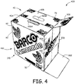
- FIG. 4 depicts a carton 400 formed from substrate material 310.
- Carton 400 is similar to what was depicted in FIG. 1 , except that graphics 410 that have been printed on the various panels and flaps comprising carton 400 were designed and laid-out according to aspects of the present invention.
- the same panel and flap nomenclature used in FIG. 1 will be used with respect to FIG. 4 .
- top panel 40 comprises flaps 40A, 40B
- right panel 90 comprises flaps 90A, 90B, 90C, 90D, 90E, and so on.
- upper panel flaps 40A, 40B each have openings 420A, 420B for ease in lifting completed carton 400.
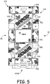
- FIG. 5 depicts substrate 310 in a planar disposition after graphics printing and cutting. It will be appreciated that images such as shown in FIG. 5 are readily generated by computer system 210 and displayed on monitor 260, for viewing and graphic manipulation by the graphics artist.
- the graphics for this panel may preferably be designed in one single graphics file.
- An embodiment of the present invention can ensure that given graphics intended to appear on a surface or panel of a completed carton, the graphics will be split up and correctly positioned on all the corresponding substrate areas.
- the orientation of graphics printed on flaps 90C and 90D, for example, are rotated relative to each other, yet when these two flaps are folded, it is necessary that their composite graphics combine to yield an accurate larger graphic.
- various panel regions 430 are shown in FIG. 5 as being devoid of graphics.
- Such regions 460 are intentionally left unprinted, as any graphics formed in these regions would not be visible in the folded, completed carton 400, as portions of other panels or flaps cover these regions 430. Since the software program 250 used to prepare the graphics has available carton structural information including location and sequence of folds, clipping masks can readily be prepared, to avoid printing in regions such as 430. Further, graphics regions likely to suffer from print ink bleeding can be identified.
- FIG. 6A is a planar view of an already cut substrate 310 with various copies of the graphics 440, 450, 460, 470, 480 shown superimposed on portions of panels and flaps of the carton 400 that will be formed from the substrate 310.
- FIG. 6A can be generated by computer system 210 for display on monitor 260.
- computer system 210 has copied the graphics f or t his s ide panel and positioned the copies onto the five flaps that contribute to this panel.
- the computer system thus generated five instances of the graphics 440, 450, 460, 470 and 480.
- a print mask is generated, e.g., by software program 250, such that only the relevant regions 440', 450', 460', 470' and 480' of panels and flaps shown in FIG. 6B will be printed with these graphics. It is understood that a similar process is carried out for each of the panels and flaps that will receive printed graphics.
- a three-dimensional image of a virtual carton bearing the graphics can be displayed, e.g., carton images 10'.
- the graphics artist (or other user of computer system 210) can of course rotate the three-dimensional image, and enlarge or zoom-view the image to visually inspect and confirm that the graphics have indeed been properly laid out.
- the graphics artist can save the graphics file information 280 to storage media 290, for use as input to a carton fabrication system 300.
- cartons or other three-dimensional form
- the carton need not be closeable, e.g., if rectangular, the carton may have only five surfaces, e.g., no top surface.
- an inverted, bottomless, pyramid-shaped structure could bear graphics designed according to aspects of the present invention, as could a multitude of other three-dimensional forms that can be created by cutting and folding a planar substrate.
Landscapes
- Engineering & Computer Science (AREA)
- Physics & Mathematics (AREA)
- Theoretical Computer Science (AREA)
- General Engineering & Computer Science (AREA)
- General Physics & Mathematics (AREA)
- Computer Hardware Design (AREA)
- Computer Graphics (AREA)
- Software Systems (AREA)
- Evolutionary Computation (AREA)
- Geometry (AREA)
- Printing Methods (AREA)
- Making Paper Articles (AREA)
Claims (14)
- Procédé, mis en oeuvre par ordinateur, pour concevoir des graphismes (410) devant être imprimés sur un substrat plat (310) qui sera découpé et plié pour obtenir un carton tridimensionnel (400) ayant des régions de surface externe qui seront imprimées avec les graphismes (410) ainsi conçus, le procédé comprenant :(a) concevoir (110) des graphismes (410) pour recouvrir des régions de surface dudit carton (400) devant être imprimées avec les graphismes (410) ;(b) superposer (120) les graphismes (410) conçus dans l'étape (a) sur une image générée par ordinateur (270) de régions dudit substrat plat (310) devant être imprimées avec les graphismes (410) ;(c) manipuler (130), au besoin, lesdits graphismes (410) conçus dans l'étape (a) pour recouvrir des régions de chaque surface précitée, comme vues sur ladite image générée par ordinateur (270) ;(d) créer (150) une image générée par ordinateur tridimensionnelle (270) dudit carton (400), ladite image (270) comprenant les graphismes (410) conçus dans l'étape (a) et, au besoin, manipulés dans l'étape (c) ;le procédé étant caractérisé par le fait qu'il comprend en outre :(e) entrer (100) des informations structurelles se rapportant audit carton (400) et comprenant au moins un parmi :i. un motif montrant des découpes devant être réalisées sur ledit substrat plat (310) pour définir au moins un parmi un panneau (40, 50, 60, 70, 80, 90) et un rabat (40A, 40B, 90A, 90B, 90C, 90D, 90E),ii. des informations définissant l'endroit où au moins un parmi un panneau (40, 50, 60, 70, 80, 90) et un rabat (40A, 40B, 90A, 90B, 90C, 90D, 90E) doit être plié sur un angle de pliage (θ), etiii. des informations se rapportant à la composition dudit substrat (310)(f) générer (140) au moins un masque de détourage pour éviter d'imprimer sur une surface dudit carton (400) qui n'est pas visible lorsque la fabrication dudit carton (400) est terminée ;(g) confirmer visuellement (150), à partir de ladite image générée par ordinateur (270) créée dans l'étape (d), l'acceptabilité de graphismes (410) recouvrant lesdites régions, et modifier, au besoin, lesdits graphismes (410) ; et(h) délivrer en sortie (160) un fichier lisible par ordinateur (280) contenant lesdits graphismes conçus (410) dont l'acceptabilité a été confirmée dans l'étape (g).
- Procédé selon l'une quelconque des revendications précédentes, en outre identifiant des régions de graphismes devant être imprimés sur ledit carton (400) qui sont susceptibles de subir un écoulement d'encre d'impression, et compensant un tel écoulement lors de la disposition desdites régions desdits graphismes.
- Procédé selon l'une quelconque des revendications précédentes, dans lequel la manipulation (130) dans l'étape (c) comprend au moins un parmi (i) une rotation, (ii) une mise à l'échelle, (iii) une copie, (iv) une découpe et (v) un collage.
- Procédé selon l'une quelconque des revendications précédentes, comprenant en outre : (h) fournir ledit fichier lisible par ordinateur (280) délivré en sortie à (g) comme entrée dans un système de fabrication de carton (300).
- Procédé selon l'une quelconque des revendications précédentes, dans lequel lesdits graphismes (410) sont conçus pour une impression sur un carton (400) ayant au moins cinq surfaces.
- Système (200) pour la conception de graphismes (410) devant être imprimés sur un substrat plat (310) qui sera découpé et plié pour obtenir un carton tridimensionnel (400) dont des régions de surface externe seront imprimées avec les graphismes (410) ainsi conçus, le système (200) comprenant :un système informatique (210) comprenant un processeur (220) apte à exécuter un programme logiciel (250) permettant à un utilisateur dudit système informatique (210) de concevoir et de manipuler des graphismes (410) et de voir lesdits graphismes (410) sur un moniteur (260) couplé audit système informatique (210) ;un support de stockage lisible par ordinateur (230, 230') contenant ledit programme logiciel (250) ;des moyens pour permettre audit utilisateur dudit système informatique (210) de concevoir des graphismes (410) pour recouvrir des régions de chaque surface dudit carton (400) devant être imprimées avec lesdits graphismes (410), et de superposer les graphismes manipulables par utilisateur (410) ainsi conçus sur une image (270), générée par ledit système informatique (210) et affichée sur ledit moniteur (260), desdites régions dudit substrat plat (310) ;des moyens pour créer une image générée par ordinateur tridimensionnelle (270) dudit carton (400) apte à être affichée sur ledit moniteur (260), ladite image (270) comprenant lesdits graphismes conçus manipulables par utilisateur (410) ;caractérisé par le fait que le système comprend en outre :des moyens pour entrer des informations structurelles se rapportant audit carton (400) dans ledit programme logiciel (250) exécuté par ledit système informatique (210), lesdites informations structurelles comprenant au moins un parmi :i. un motif montrant des découpes devant être réalisées sur ledit substrat plat (310) pour définir au moins un parmi un panneau (40, 50, 60, 70, 80, 90) et un rabat (40A, 40B, 90A, 90B, 90C, 90D, 90E),ii. des informations définissant l'endroit où au moins un parmi un panneau (40, 50, 60, 70, 80, 90) et un rabat (40A, 40B, 90A, 90B, 90C, 90D, 90E) doit être plié sur un angle de pliage (θ), etiii. des informations se rapportant à la composition dudit substrat (310)des moyens pour générer au moins un masque de détourage pour éviter d'imprimer sur une surface dudit carton (400) qui n'est pas visible lorsque la fabrication dudit carton (400) est terminéeledit utilisateur pouvant confirmer visuellement (150), à partir de ladite image générée par ordinateur tridimensionnelle (270), l'acceptabilité desdits graphismes (410) et pouvant modifier, au besoin, lesdits graphismes (410) ; etdes moyens pour délivrer en sortie un fichier lisible par ordinateur (280) contenant lesdits graphismes conçus (410) dont l'acceptabilité a été confirmée par ledit utilisateur.
- Procédé selon la revendication 6, dans lequel lesdites informations structurelles comprennent au moins un parmi :i. un motif montrant des découpes devant être réalisées sur ledit substrat plat (310) pour définir au moins un parmi un panneau (40, 50, 60, 70, 80, 90) et un rabat (40A, 40B, 90A, 90B, 90C, 90D, 90E),ii. des informations définissant l'endroit où au moins un parmi un panneau (40, 50, 60, 70, 80, 90) et un rabat (40A, 40B, 90A, 90B, 90C, 90D, 90E) doit être plié sur un angle de pliage (θ), etiii. des informations se rapportant à la composition dudit substrat (310).
- Système selon l'une quelconque des revendications 6 et 7, comprenant en outre des moyens pour identifier des régions de graphismes (410) devant être imprimés sur ledit carton (400) qui sont susceptibles de subir un écoulement d'encre d'impression et compenser un tel écoulement lors de la disposition desdites régions desdits graphismes (410).
- Système selon l'une quelconque des revendications 6 à 8, dans lequel la manipulation desdits graphismes par l'utilisateur comprend au moins un parmi (i) une rotation, (ii) une mise à l'échelle, (iii) une copie, (iv) une découpe et (v) un collage.
- Système selon l'une quelconque des revendications 6 à 9, comprenant en outre :un système de fabrication de carton (300) dans lequel ledit fichier lisible par ordinateur (280) délivré en sortie par ledit système informatique (210) est entré pour commander au moins l'impression de cartons (400) dans ledit système de fabrication de carton (300).
- Système selon la revendication 10, dans lequel le système de fabrication de carton assure l'impression dudit substrat (310) avec lesdits graphismes (410) avant que ledit substrat (731) ne soit découpé.
- Système selon la revendication 10, dans lequel le système de fabrication de carton comprend l'identification de régions de graphismes (410) devant être imprimés sur ledit carton (400) qui sont susceptibles de subir un écoulement d'encre d'impression et la compensation d'un tel écoulement lors de la disposition desdites régions desdits graphismes (410).
- Support lisible par ordinateur (230, 230') stockant un programme logiciel (250) qui, lorsqu'il est exécuté par un processeur informatique (220), exécutera les étapes suivantes pour aider à concevoir des graphismes (410) devant être imprimés sur un substrat plat (310) qui sera découpé et plié pour obtenir un carton tridimensionnel (400) dont des régions de surface externe seront imprimées avec les graphismes (410) :(a) permettre à un utilisateur dudit programme logiciel (250) de concevoir (110) des graphismes (410) pour recouvrir des régions de chaque surface dudit carton (400) qui doit être imprimé avec les graphismes (410) ;(b) superposer (120) les graphismes (410) conçus dans l'étape (a) sur une image générée par ordinateur de régions dudit substrat plat (310) devant être imprimées avec les graphismes (410) ;(c) manipuler (130), au besoin, lesdits graphismes (410) conçus dans l'étape (a) pour recouvrir lesdites régions de chaque surface, comme vues sur ladite image générée par ordinateur ;(d) créer (150) une image générée par ordinateur tridimensionnelle dudit carton (400), ladite image comprenant les graphismes (410) conçus dans l'étape (a) et, au besoin, manipulés dans l'étape (c) ;caractérisé par les étapes suivantes :(e) recevoir (100), comme entrée, des informations structurelles se rapportant audit carton (400) et comprenant au moins un parmi :i. un motif montrant des découpes devant être réalisées sur ledit substrat plat (310) pour définir au moins un parmi un panneau (40, 50, 60, 70, 80, 90) et un rabat (40A, 40B, 90A, 90B, 90C, 90D, 90E),ii. des informations définissant l'endroit où au moins un parmi un panneau (40, 50, 60, 70, 80, 90) et un rabat (40A, 40B, 90A, 90B, 90C, 90D, 90E) doit être plié sur un angle de pliage (θ), etiii. des informations se rapportant à la composition dudit substrat (310)(f) générer (140) au moins un masque de détourage pour éviter d'imprimer sur une surface dudit carton (400) qui n'est pas visible lorsque la fabrication dudit carton est terminée ;(g) permettre à un utilisateur dudit programme logiciel de confirmer visuellement (150), à partir de ladite image générée par ordinateur créée dans l'étape (d), l'acceptabilité de graphismes (410) recouvrant lesdites régions et modifiant, au besoin, lesdits graphismes (410) ; et(h) délivrer en sortie (160) un fichier lisible par ordinateur (280) contenant lesdits graphismes conçus (410) dont l'acceptabilité a été confirmée dans l'étape (t).
- Support lisible par ordinateur selon la revendication 13, dans lequel ledit fichier lisible par ordinateur (280) délivré en sortie dans l'étape (g) peut être utilisé comme entrée dans un système de fabrication de carton (300).
Applications Claiming Priority (2)
| Application Number | Priority Date | Filing Date | Title |
|---|---|---|---|
| US10/762,217 US7599088B2 (en) | 2004-01-21 | 2004-01-21 | Method for designing two-dimensional graphics for use on three-dimensional cartons bearing such graphics |
| US762217 | 2004-01-21 |
Publications (3)
| Publication Number | Publication Date |
|---|---|
| EP1557795A2 EP1557795A2 (fr) | 2005-07-27 |
| EP1557795A3 EP1557795A3 (fr) | 2006-07-26 |
| EP1557795B1 true EP1557795B1 (fr) | 2016-12-28 |
Family
ID=34634592
Family Applications (1)
| Application Number | Title | Priority Date | Filing Date |
|---|---|---|---|
| EP05075126.2A Expired - Lifetime EP1557795B1 (fr) | 2004-01-21 | 2005-01-19 | Procedé de conception des images à deux dimensions à utiliser sur des cartons tridimensionnels |
Country Status (2)
| Country | Link |
|---|---|
| US (1) | US7599088B2 (fr) |
| EP (1) | EP1557795B1 (fr) |
Families Citing this family (24)
| Publication number | Priority date | Publication date | Assignee | Title |
|---|---|---|---|---|
| NL1028365C2 (nl) * | 2005-02-22 | 2006-08-23 | Paul Gokkel | Bouwsysteem en inbindsysteem. |
| KR100739446B1 (ko) * | 2005-05-04 | 2007-07-13 | 주식회사 모든박스 | 3차원 입체도 변환 시스템 및 방법 |
| US7346408B2 (en) | 2005-09-06 | 2008-03-18 | Esko Ip Nv | Two-dimensional graphics for incorporating on three-dimensional objects |
| US8830223B2 (en) * | 2008-05-08 | 2014-09-09 | Esko Software Bvba | Computer aided design of three-dimensional cartons with curved creases |
| US8219227B2 (en) * | 2008-08-19 | 2012-07-10 | Eastman Kodak Company | Merging variable data for packaging imposition |
| DE102008038608A1 (de) * | 2008-08-21 | 2010-02-25 | Heidelberger Druckmaschinen Ag | Verfahren und Einrichtung zum Drucken von unterschiedlichen Nutzen auf einem Druckbogen |
| US9082207B2 (en) * | 2009-11-18 | 2015-07-14 | Xerox Corporation | System and method for automatic layout of printed material on a three-dimensional structure |
| US8643874B2 (en) * | 2009-12-18 | 2014-02-04 | Xerox Corporation | Method and system for generating a workflow to produce a dimensional document |
| US8659785B2 (en) | 2011-11-11 | 2014-02-25 | Xerox Corporation | Methods and systems for creating structural documents having background content |
| US8659784B2 (en) | 2011-11-11 | 2014-02-25 | Xerox Corporation | Methods and systems for creating structural documents |
| US8994734B2 (en) * | 2012-07-31 | 2015-03-31 | Xerox Corporation | Package definition system |
| US9641722B2 (en) | 2012-08-24 | 2017-05-02 | Xerox Corporation | Methods and systems for creating structural documents with security features |
| US8797605B2 (en) | 2012-08-24 | 2014-08-05 | Xerox Corporation | Methods and systems for creating structural document packages for products |
| US8792142B2 (en) | 2012-08-24 | 2014-07-29 | Xerox Corporation | Methods and systems for creating structural documents having contact information for utilizing product information |
| US8797604B2 (en) * | 2012-08-24 | 2014-08-05 | Xerox Corporation | Methods and systems for creating structural documents |
| US9460056B2 (en) | 2013-01-22 | 2016-10-04 | Xerox Corporation | Dynamic image layout for personalized packages |
| US9916401B2 (en) * | 2015-05-18 | 2018-03-13 | Xerox Corporation | Creation of cut files for personalized package design using multiple substrates |
| US9916402B2 (en) * | 2015-05-18 | 2018-03-13 | Xerox Corporation | Creation of cut files to fit a large package flat on one or more substrates |
| US10372108B2 (en) * | 2015-08-08 | 2019-08-06 | PopUp Play Inc. | Production of components of custom structures |
| US9654666B1 (en) | 2015-11-19 | 2017-05-16 | Xerox Corporation | Direct scan to package printing |
| CN108229075B (zh) * | 2018-02-12 | 2020-10-27 | 中国科学技术大学 | 折叠纸盒的辅助设计方法 |
| US11402963B2 (en) * | 2018-10-15 | 2022-08-02 | Adobe Inc. | Neighboring panel view |
| US20230191275A1 (en) * | 2021-12-17 | 2023-06-22 | Envegami, LLC | Methods and computer-readable media for graphical image manipulation |
| CN120246379B (zh) * | 2025-06-05 | 2025-08-22 | 甘肃陇小南电子商务有限公司 | 快递纸盒印刷包装系统及方法 |
Family Cites Families (7)
| Publication number | Priority date | Publication date | Assignee | Title |
|---|---|---|---|---|
| US5109479A (en) * | 1989-09-07 | 1992-04-28 | Amp-Akzo Corporation | Method of designing three dimensional electrical circuits |
| US5538288A (en) * | 1995-06-07 | 1996-07-23 | Heath; Mark P. | Parallelogram sheet for forming a reversible parallelepiped |
| US6117061A (en) * | 1997-07-21 | 2000-09-12 | Avery Dennison Corporation | Method for custom printing and forming three-dimensional structures |
| EP1105291A4 (fr) * | 1998-04-03 | 2002-06-05 | Wade H Kirchmeyer | Procedes et dispositif servant a personnaliser la configuration de photocubes |
| US6689035B1 (en) * | 2000-04-11 | 2004-02-10 | Gerber Scientific Products, Inc. | Method and apparatus for designing and creating a package |
| US20040160640A1 (en) * | 2001-08-16 | 2004-08-19 | Corrales Richard C. | Systems and methods for creating three-dimensional and animated images |
| DE10158083C1 (de) * | 2001-11-27 | 2003-04-24 | Heidelberger Druckmasch Ag | Verfahren und System zur Erzeugung von Proofdaten für den Verpackungsdruck |
-
2004
- 2004-01-21 US US10/762,217 patent/US7599088B2/en active Active
-
2005
- 2005-01-19 EP EP05075126.2A patent/EP1557795B1/fr not_active Expired - Lifetime
Non-Patent Citations (1)
| Title |
|---|
| None * |
Also Published As
| Publication number | Publication date |
|---|---|
| US7599088B2 (en) | 2009-10-06 |
| EP1557795A3 (fr) | 2006-07-26 |
| US20050157342A1 (en) | 2005-07-21 |
| EP1557795A2 (fr) | 2005-07-27 |
Similar Documents
| Publication | Publication Date | Title |
|---|---|---|
| US7599088B2 (en) | Method for designing two-dimensional graphics for use on three-dimensional cartons bearing such graphics | |
| US8830223B2 (en) | Computer aided design of three-dimensional cartons with curved creases | |
| US7346408B2 (en) | Two-dimensional graphics for incorporating on three-dimensional objects | |
| US8587611B2 (en) | Document verification system | |
| WO2018080542A1 (fr) | Développement d'une interface utilisateur non rectangulaire | |
| CN112470194A (zh) | 用于生成和查看具有印刷特征的对象的3d可视化的方法和系统 | |
| GB2506273A (en) | Creating a customised three-dimensional model constructed from a two-dimensional printed template | |
| KR102742648B1 (ko) | 판지상자의 이미지를 가상으로 디스플레이하기 위한 방법과 컴퓨터 시스템 | |
| US7385724B2 (en) | Photo manager | |
| US20150213155A1 (en) | Package definition system with non-symmetric functional elements as a function of package edge property | |
| US20050168459A1 (en) | System and method for packaging design | |
| JPS62212880A (ja) | 紙器の設計方法 | |
| Ahmadovna et al. | Methodology of using autocad software in developing technical creativity of students | |
| JP2008310745A (ja) | 画像処理装置、紙器作製システム、紙器の印刷用画像データ生成方法、およびプログラム | |
| Wood | Adobe Illustrator CC Classroom in a Book (2014 release) | |
| CN104239626B (zh) | 用于设计折叠片对象的方法、装置、介质和系统 | |
| John | CAD fundamentals for architecture | |
| Zhu et al. | Cartonist: Automatic Synthesis and Interactive Exploration of Nonstandard Carton Design | |
| Omura et al. | Mastering AutoCAD 2015 and AutoCAD LT 2015: Autodesk Official Press | |
| US20230191275A1 (en) | Methods and computer-readable media for graphical image manipulation | |
| Shih | Tools for Design Using AutoCAD 2021 and Autodesk Inventor 2021 | |
| Shrock | Exercise workbook for beginning AutoCAD | |
| Gray et al. | A simulator for origami-inspired self-reconfigurable robots | |
| Shih | Tools for Design Using AutoCAD 2013 and Autodesk Inventor 2013 | |
| JPH08161383A (ja) | 図面作成装置 |
Legal Events
| Date | Code | Title | Description |
|---|---|---|---|
| PUAI | Public reference made under article 153(3) epc to a published international application that has entered the european phase |
Free format text: ORIGINAL CODE: 0009012 |
|
| AK | Designated contracting states |
Kind code of ref document: A2 Designated state(s): AT BE BG CH CY CZ DE DK EE ES FI FR GB GR HU IE IS IT LI LT LU MC NL PL PT RO SE SI SK TR |
|
| AX | Request for extension of the european patent |
Extension state: AL BA HR LV MK YU |
|
| PUAL | Search report despatched |
Free format text: ORIGINAL CODE: 0009013 |
|
| AK | Designated contracting states |
Kind code of ref document: A3 Designated state(s): AT BE BG CH CY CZ DE DK EE ES FI FR GB GR HU IE IS IT LI LT LU MC NL PL PT RO SE SI SK TR |
|
| AX | Request for extension of the european patent |
Extension state: AL BA HR LV MK YU |
|
| 17P | Request for examination filed |
Effective date: 20060125 |
|
| AKX | Designation fees paid |
Designated state(s): AT BE BG CH CY CZ DE DK EE ES FI FR GB GR HU IE IS IT LI LT LU MC NL PL PT RO SE SI SK TR |
|
| R17P | Request for examination filed (corrected) |
Effective date: 20060125 |
|
| 17Q | First examination report despatched |
Effective date: 20070831 |
|
| RAP1 | Party data changed (applicant data changed or rights of an application transferred) |
Owner name: ESKO IP NV |
|
| RAP1 | Party data changed (applicant data changed or rights of an application transferred) |
Owner name: ESKO SOFTWARE BVBA |
|
| REG | Reference to a national code |
Ref country code: DE Ref legal event code: R079 Ref document number: 602005050991 Country of ref document: DE Free format text: PREVIOUS MAIN CLASS: G06T0017400000 Ipc: G06T0019000000 |
|
| RIC1 | Information provided on ipc code assigned before grant |
Ipc: G06F 17/50 20060101ALI20160517BHEP Ipc: G06T 19/00 20110101AFI20160517BHEP |
|
| GRAP | Despatch of communication of intention to grant a patent |
Free format text: ORIGINAL CODE: EPIDOSNIGR1 |
|
| INTG | Intention to grant announced |
Effective date: 20160718 |
|
| STAA | Information on the status of an ep patent application or granted ep patent |
Free format text: STATUS: GRANT OF PATENT IS INTENDED |
|
| GRAS | Grant fee paid |
Free format text: ORIGINAL CODE: EPIDOSNIGR3 |
|
| GRAA | (expected) grant |
Free format text: ORIGINAL CODE: 0009210 |
|
| STAA | Information on the status of an ep patent application or granted ep patent |
Free format text: STATUS: THE PATENT HAS BEEN GRANTED |
|
| AK | Designated contracting states |
Kind code of ref document: B1 Designated state(s): AT BE BG CH CY CZ DE DK EE ES FI FR GB GR HU IE IS IT LI LT LU MC NL PL PT RO SE SI SK TR |
|
| REG | Reference to a national code |
Ref country code: GB Ref legal event code: FG4D |
|
| REG | Reference to a national code |
Ref country code: CH Ref legal event code: EP |
|
| REG | Reference to a national code |
Ref country code: AT Ref legal event code: REF Ref document number: 857888 Country of ref document: AT Kind code of ref document: T Effective date: 20170115 |
|
| REG | Reference to a national code |
Ref country code: IE Ref legal event code: FG4D Ref country code: FR Ref legal event code: PLFP Year of fee payment: 13 |
|
| REG | Reference to a national code |
Ref country code: DE Ref legal event code: R096 Ref document number: 602005050991 Country of ref document: DE |
|
| REG | Reference to a national code |
Ref country code: LT Ref legal event code: MG4D |
|
| PG25 | Lapsed in a contracting state [announced via postgrant information from national office to epo] |
Ref country code: GR Free format text: LAPSE BECAUSE OF FAILURE TO SUBMIT A TRANSLATION OF THE DESCRIPTION OR TO PAY THE FEE WITHIN THE PRESCRIBED TIME-LIMIT Effective date: 20170329 Ref country code: SE Free format text: LAPSE BECAUSE OF FAILURE TO SUBMIT A TRANSLATION OF THE DESCRIPTION OR TO PAY THE FEE WITHIN THE PRESCRIBED TIME-LIMIT Effective date: 20161228 Ref country code: LT Free format text: LAPSE BECAUSE OF FAILURE TO SUBMIT A TRANSLATION OF THE DESCRIPTION OR TO PAY THE FEE WITHIN THE PRESCRIBED TIME-LIMIT Effective date: 20161228 |
|
| REG | Reference to a national code |
Ref country code: NL Ref legal event code: MP Effective date: 20161228 |
|
| REG | Reference to a national code |
Ref country code: AT Ref legal event code: MK05 Ref document number: 857888 Country of ref document: AT Kind code of ref document: T Effective date: 20161228 |
|
| PG25 | Lapsed in a contracting state [announced via postgrant information from national office to epo] |
Ref country code: BE Free format text: LAPSE BECAUSE OF NON-PAYMENT OF DUE FEES Effective date: 20170131 Ref country code: FI Free format text: LAPSE BECAUSE OF FAILURE TO SUBMIT A TRANSLATION OF THE DESCRIPTION OR TO PAY THE FEE WITHIN THE PRESCRIBED TIME-LIMIT Effective date: 20161228 |
|
| PG25 | Lapsed in a contracting state [announced via postgrant information from national office to epo] |
Ref country code: NL Free format text: LAPSE BECAUSE OF FAILURE TO SUBMIT A TRANSLATION OF THE DESCRIPTION OR TO PAY THE FEE WITHIN THE PRESCRIBED TIME-LIMIT Effective date: 20161228 |
|
| PG25 | Lapsed in a contracting state [announced via postgrant information from national office to epo] |
Ref country code: IS Free format text: LAPSE BECAUSE OF FAILURE TO SUBMIT A TRANSLATION OF THE DESCRIPTION OR TO PAY THE FEE WITHIN THE PRESCRIBED TIME-LIMIT Effective date: 20170428 Ref country code: SK Free format text: LAPSE BECAUSE OF FAILURE TO SUBMIT A TRANSLATION OF THE DESCRIPTION OR TO PAY THE FEE WITHIN THE PRESCRIBED TIME-LIMIT Effective date: 20161228 Ref country code: CZ Free format text: LAPSE BECAUSE OF FAILURE TO SUBMIT A TRANSLATION OF THE DESCRIPTION OR TO PAY THE FEE WITHIN THE PRESCRIBED TIME-LIMIT Effective date: 20161228 Ref country code: EE Free format text: LAPSE BECAUSE OF FAILURE TO SUBMIT A TRANSLATION OF THE DESCRIPTION OR TO PAY THE FEE WITHIN THE PRESCRIBED TIME-LIMIT Effective date: 20161228 Ref country code: RO Free format text: LAPSE BECAUSE OF FAILURE TO SUBMIT A TRANSLATION OF THE DESCRIPTION OR TO PAY THE FEE WITHIN THE PRESCRIBED TIME-LIMIT Effective date: 20161228 |
|
| PG25 | Lapsed in a contracting state [announced via postgrant information from national office to epo] |
Ref country code: BG Free format text: LAPSE BECAUSE OF FAILURE TO SUBMIT A TRANSLATION OF THE DESCRIPTION OR TO PAY THE FEE WITHIN THE PRESCRIBED TIME-LIMIT Effective date: 20170328 Ref country code: PT Free format text: LAPSE BECAUSE OF FAILURE TO SUBMIT A TRANSLATION OF THE DESCRIPTION OR TO PAY THE FEE WITHIN THE PRESCRIBED TIME-LIMIT Effective date: 20170428 Ref country code: ES Free format text: LAPSE BECAUSE OF FAILURE TO SUBMIT A TRANSLATION OF THE DESCRIPTION OR TO PAY THE FEE WITHIN THE PRESCRIBED TIME-LIMIT Effective date: 20161228 Ref country code: BE Free format text: LAPSE BECAUSE OF FAILURE TO SUBMIT A TRANSLATION OF THE DESCRIPTION OR TO PAY THE FEE WITHIN THE PRESCRIBED TIME-LIMIT Effective date: 20161228 Ref country code: AT Free format text: LAPSE BECAUSE OF FAILURE TO SUBMIT A TRANSLATION OF THE DESCRIPTION OR TO PAY THE FEE WITHIN THE PRESCRIBED TIME-LIMIT Effective date: 20161228 Ref country code: PL Free format text: LAPSE BECAUSE OF FAILURE TO SUBMIT A TRANSLATION OF THE DESCRIPTION OR TO PAY THE FEE WITHIN THE PRESCRIBED TIME-LIMIT Effective date: 20161228 |
|
| REG | Reference to a national code |
Ref country code: CH Ref legal event code: PL |
|
| PG25 | Lapsed in a contracting state [announced via postgrant information from national office to epo] |
Ref country code: MC Free format text: LAPSE BECAUSE OF FAILURE TO SUBMIT A TRANSLATION OF THE DESCRIPTION OR TO PAY THE FEE WITHIN THE PRESCRIBED TIME-LIMIT Effective date: 20161228 |
|
| REG | Reference to a national code |
Ref country code: DE Ref legal event code: R097 Ref document number: 602005050991 Country of ref document: DE |
|
| PG25 | Lapsed in a contracting state [announced via postgrant information from national office to epo] |
Ref country code: IT Free format text: LAPSE BECAUSE OF FAILURE TO SUBMIT A TRANSLATION OF THE DESCRIPTION OR TO PAY THE FEE WITHIN THE PRESCRIBED TIME-LIMIT Effective date: 20161228 Ref country code: LI Free format text: LAPSE BECAUSE OF NON-PAYMENT OF DUE FEES Effective date: 20170131 Ref country code: CH Free format text: LAPSE BECAUSE OF NON-PAYMENT OF DUE FEES Effective date: 20170131 |
|
| REG | Reference to a national code |
Ref country code: IE Ref legal event code: MM4A |
|
| PLBE | No opposition filed within time limit |
Free format text: ORIGINAL CODE: 0009261 |
|
| STAA | Information on the status of an ep patent application or granted ep patent |
Free format text: STATUS: NO OPPOSITION FILED WITHIN TIME LIMIT |
|
| PG25 | Lapsed in a contracting state [announced via postgrant information from national office to epo] |
Ref country code: DK Free format text: LAPSE BECAUSE OF FAILURE TO SUBMIT A TRANSLATION OF THE DESCRIPTION OR TO PAY THE FEE WITHIN THE PRESCRIBED TIME-LIMIT Effective date: 20161228 Ref country code: LU Free format text: LAPSE BECAUSE OF NON-PAYMENT OF DUE FEES Effective date: 20170119 |
|
| 26N | No opposition filed |
Effective date: 20170929 |
|
| REG | Reference to a national code |
Ref country code: FR Ref legal event code: PLFP Year of fee payment: 14 |
|
| PG25 | Lapsed in a contracting state [announced via postgrant information from national office to epo] |
Ref country code: IE Free format text: LAPSE BECAUSE OF NON-PAYMENT OF DUE FEES Effective date: 20170119 Ref country code: SI Free format text: LAPSE BECAUSE OF FAILURE TO SUBMIT A TRANSLATION OF THE DESCRIPTION OR TO PAY THE FEE WITHIN THE PRESCRIBED TIME-LIMIT Effective date: 20161228 |
|
| REG | Reference to a national code |
Ref country code: DE Ref legal event code: R082 Ref document number: 602005050991 Country of ref document: DE Representative=s name: MUELLER-BORE & PARTNER PATENTANWAELTE PARTG MB, DE |
|
| PG25 | Lapsed in a contracting state [announced via postgrant information from national office to epo] |
Ref country code: HU Free format text: LAPSE BECAUSE OF FAILURE TO SUBMIT A TRANSLATION OF THE DESCRIPTION OR TO PAY THE FEE WITHIN THE PRESCRIBED TIME-LIMIT; INVALID AB INITIO Effective date: 20050119 |
|
| PG25 | Lapsed in a contracting state [announced via postgrant information from national office to epo] |
Ref country code: CY Free format text: LAPSE BECAUSE OF NON-PAYMENT OF DUE FEES Effective date: 20161228 |
|
| PG25 | Lapsed in a contracting state [announced via postgrant information from national office to epo] |
Ref country code: TR Free format text: LAPSE BECAUSE OF FAILURE TO SUBMIT A TRANSLATION OF THE DESCRIPTION OR TO PAY THE FEE WITHIN THE PRESCRIBED TIME-LIMIT Effective date: 20161228 |
|
| PGFP | Annual fee paid to national office [announced via postgrant information from national office to epo] |
Ref country code: DE Payment date: 20240119 Year of fee payment: 20 Ref country code: GB Payment date: 20240123 Year of fee payment: 20 |
|
| PGFP | Annual fee paid to national office [announced via postgrant information from national office to epo] |
Ref country code: FR Payment date: 20240124 Year of fee payment: 20 |
|
| REG | Reference to a national code |
Ref country code: DE Ref legal event code: R071 Ref document number: 602005050991 Country of ref document: DE |
|
| REG | Reference to a national code |
Ref country code: GB Ref legal event code: PE20 Expiry date: 20250118 |
|
| PG25 | Lapsed in a contracting state [announced via postgrant information from national office to epo] |
Ref country code: GB Free format text: LAPSE BECAUSE OF EXPIRATION OF PROTECTION Effective date: 20250118 |