EP1557844A2 - Utilisation d'une couche extérieure sur un mirroir pour un appareil lithographique, mirroir et appareil lithographique le comprenant et procédé de fabrication d'un composant - Google Patents
Utilisation d'une couche extérieure sur un mirroir pour un appareil lithographique, mirroir et appareil lithographique le comprenant et procédé de fabrication d'un composant Download PDFInfo
- Publication number
- EP1557844A2 EP1557844A2 EP04077836A EP04077836A EP1557844A2 EP 1557844 A2 EP1557844 A2 EP 1557844A2 EP 04077836 A EP04077836 A EP 04077836A EP 04077836 A EP04077836 A EP 04077836A EP 1557844 A2 EP1557844 A2 EP 1557844A2
- Authority
- EP
- European Patent Office
- Prior art keywords
- mirror
- lithographic apparatus
- radiation
- metal particles
- top layer
- Prior art date
- Legal status (The legal status is an assumption and is not a legal conclusion. Google has not performed a legal analysis and makes no representation as to the accuracy of the status listed.)
- Withdrawn
Links
Images


Classifications
-
- G—PHYSICS
- G21—NUCLEAR PHYSICS; NUCLEAR ENGINEERING
- G21K—HANDLING OF PARTICLES OR IONISING RADIATION NOT OTHERWISE PROVIDED FOR; IRRADIATION DEVICES; GAMMA RAY OR X-RAY MICROSCOPES
- G21K1/00—Arrangements for handling particles or ionising radiation, e.g. focusing or moderating
- G21K1/06—Arrangements for handling particles or ionising radiation, e.g. focusing or moderating using diffraction, refraction or reflection, e.g. monochromators
-
- G—PHYSICS
- G03—PHOTOGRAPHY; CINEMATOGRAPHY; ANALOGOUS TECHNIQUES USING WAVES OTHER THAN OPTICAL WAVES; ELECTROGRAPHY; HOLOGRAPHY
- G03F—PHOTOMECHANICAL PRODUCTION OF TEXTURED OR PATTERNED SURFACES, e.g. FOR PRINTING, FOR PROCESSING OF SEMICONDUCTOR DEVICES; MATERIALS THEREFOR; ORIGINALS THEREFOR; APPARATUS SPECIALLY ADAPTED THEREFOR
- G03F7/00—Photomechanical, e.g. photolithographic, production of textured or patterned surfaces, e.g. printing surfaces; Materials therefor, e.g. comprising photoresists; Apparatus specially adapted therefor
- G03F7/70—Microphotolithographic exposure; Apparatus therefor
- G03F7/708—Construction of apparatus, e.g. environment aspects, hygiene aspects or materials
- G03F7/70908—Hygiene, e.g. preventing apparatus pollution, mitigating effect of pollution or removing pollutants from apparatus
- G03F7/70925—Cleaning, i.e. actively freeing apparatus from pollutants, e.g. using plasma cleaning
Definitions
- the present invention relates to a lithographic apparatus and a device manufacturing method.
- a lithographic apparatus is a machine that applies a desired pattern onto a target portion of a substrate.
- Lithographic apparatus can be used, for example, in the manufacture of integrated circuits (ICs).
- a patterning means such as a mask, may be used to generate a circuit pattern corresponding to an individual layer of the IC, and this pattern can be imaged onto a target portion (e.g. comprising part of, one or several dies) on a substrate (e.g. a silicon wafer) that has a layer of radiation-sensitive material (resist).
- a single substrate will contain a network of adjacent target portions that are successively exposed.
- lithographic apparatus include so-called steppers, in which each target portion is irradiated by exposing an entire pattern onto the target portion in one go, and so-called scanners, in which each target portion is irradiated by scanning the pattern through the projection beam in a given direction (the "scanning"-direction) while synchronously scanning the substrate parallel or anti-parallel to this direction.
- EUV extreme ultraviolet
- Sn nm tin
- a top layer of a predetermined metal is used on a mirror for use in a lithographic apparatus comprising a source to provide radiation of a desired wavelength to reduce the forming of a metal deposition on the mirror by a stream of undesired metal particles generated by the source in operation, the predetermined metal being selected such that it interdiffuses in a predetermined temperature range with the metal deposition, when the lithographic apparatus is in operation.
- the mirror may have a top layer of a metal with a very high reflectivity, e.g., a multi-layer mirror provided with a top layer of Ru. Without a stream of undesired metal particles, a radiation collector provided with such a mirror would have a transmission for EUV of 77%. However, if such a mirror collects such undesired metal particles the reflectivity and transmission is reduced drastically. For instance, if the undesired metal particles comprise Sn and the Sn is deposited as a layer of 10 nm or more, the transmission of such a multi-layer mirror may reduce to 21% for EUV.
- a metal with a very high reflectivity e.g., a multi-layer mirror provided with a top layer of Ru.
- the top layer is now selected such that the metal of the top layer interdiffuses with the undesired metal particles when deposited on the top layer.
- the top layer may be made of Au.
- an Au/Sn alloy film will result on the top layer of Au.
- the collector transmission of such a mirror may be approximately 0.40, which is significantly higher than the transmission of 0.21 of a mirror with a Sn layer only.
- the invention relates to a use of a top layer of one or more predetermined materials on a mirror for use in a lithographic apparatus comprising a source to provide radiation of a desired wavelength and that, in operation, generates a stream of undesired metal particles to form a metal deposition on the mirror to extend lifetime of nuclei in a nucleation stage of the metal deposition, which nuclei will be formed when the metal particles are deposited on the top layer when the lithographic apparatus is in operation.
- the thin film growth will be in the nucleation stage as long as possible and a coalescence process will be delayed as much as possible, thereby avoiding a continuous film to be formed on the mirror as long as possible.
- the invention relates to a mirror for use in a lithographic apparatus comprising a source to provide radiation of a desired wavelength and that, in operation, generates a stream of undesired metal particles to form a metal deposition on the mirror, the mirror being, at least partly, covered with a top layer of one or more predetermined materials, the one or more predetermined materials being selected such that it enhances wetting of the metal deposition only on predetermined areas of the top layer.
- wetting is defined as the tendency of a liquid to spread over a surface. The higher the wetting by the liquid, the lower a contact angle between the liquid and the surface.
- the metal deposition is in the form of a liquid.
- the present invention relates to a mirror for use in a lithographic apparatus comprising a source to provide radiation of a desired wavelength and that, in operation, generates a stream of undesired metal particles, the mirror being designed to gather and remove the metal particles by capillary action when they are deposited on the mirror when the lithographic apparatus is in operation.
- the mirror may comprise at least one of trenches and holes in the mirror that are, preferably, coated with a wetting material. These trenches and holes collect nuclei of the undesired metal particles and guide them away from the reflective mirror surface.
- the invention also relates to a lithographic apparatus that is provided with one or more of the mirrors as defined above or that uses a top layer on one or more of the mirrors as defined above.
- Such a lithographic apparatus may be provided with a heating source to heat the mirror and increase surface mobility of the undesired metal particles on the mirror. Thereby, the deposited undesired metal particles will be evaporated more easily. The evaporation of the undesired metal particles may, moreover, be stimulated by providing a predetermined halogen gas to the surface of the mirror.
- the invention relates to a device as manufactured by such a lithographic apparatus as defined above.
- the present invention relates to a lithographic apparatus according to claim 20.
- the lithographic apparatus according to claim 20 comprises a heating source to heat the mirror and increase surface mobility of the metal particles on the mirror, thereby stimulating evaporation of these metal particles from the mirror.
- such evaporated metal particles may be pumped away by means of a pump.
- Such a lithographic apparatus may comprise a plurality of mirrors arranged as a radiation collector, at least one mirror comprising a rear surface facing a front surface of another mirror, the rear surface of the at least one mirror being arranged to receive metal particles evaporated from the front surface of the other mirror and to operate as a condensation surface.
- a condensation surface may be formed by a separate unit behind the at least one mirror, or may be the rear surface of the at least one mirror itself. It functions as a cooling object for the evaporated metal particles in order to stimulate condensation.
- a predetermined halogen gas may be used.
- this lithographic apparatus may be used to manufacture devices, like substrates.
- lithographic apparatus in the manufacture of ICs, it should be understood that the lithographic apparatus described herein may have other applications, such as the manufacture of integrated optical systems, guidance and detection patterns for magnetic domain memories, liquid-crystal displays (LCDs), thin-film magnetic heads, etc.
- LCDs liquid-crystal displays
- any use of the terms “wafer” or “die” herein may be considered as synonymous with the more general terms “substrate” or "target portion”, respectively.
- the substrate referred to herein may be processed, before or after exposure, in for example a track (a tool that typically applies a layer of resist to a substrate and develops the exposed resist) or a metrology or inspection tool.
- the disclosure herein may be applied to such and other substrate processing tools.
- the substrate may be processed more than once, for example in order to create a multi-layer IC, so that the term substrate used herein may also refer to a substrate that already contains multiple processed layers.
- UV radiation e.g. having a wavelength of 365, 248, 193, 157 or 126 nm
- EUV extreme ultra-violet
- particle beams such as ion beams or electron beams.
- patterning means used herein should be broadly interpreted as referring to means that can be used to impart a projection beam with a pattern in its cross-section such as to create a pattern in a target portion of the substrate. It should be noted that the pattern imparted to the projection beam may not exactly correspond to the desired pattern in the target portion of the substrate. Generally, the pattern imparted to the projection beam will correspond to a particular functional layer in a device being created in the target portion, such as an integrated circuit.
- Patterning means may be transmissive or reflective.
- Examples of patterning means include masks, programmable mirror arrays, and programmable LCD panels.
- Masks are well known in lithography, and include mask types such as binary, alternating phase-shift, and attenuated phase-shift, as well as various hybrid mask types.
- An example of a programmable mirror array employs a matrix arrangement of small mirrors, each of which can be individually tilted so as to reflect an incoming radiation beam in different directions; in this manner, the reflected beam is patterned.
- the support structure may be a frame or table, for example, which may be fixed or movable as required and which may ensure that the patterning means is at a desired position, for example with respect to the projection system. Any use of the terms "reticle” or “mask” herein may be considered synonymous with the more general term "patterning means”.
- projection system used herein should be broadly interpreted as encompassing various types of projection system, including refractive optical systems, reflective optical systems, and catadioptric optical systems, as appropriate for example for the exposure radiation being used, or for other factors such as the use of an immersion fluid or the use of a vacuum. Any use of the term “lens” herein may be considered as synonymous with the more general term “projection system”.
- the illumination system may also encompass various types of optical components, including refractive, reflective, and catadioptric optical components for directing, shaping, or controlling the projection beam of radiation, and such components may also be referred to below, collectively or singularly, as a "lens”.
- the lithographic apparatus may be of a type having two (dual stage) or more substrate tables (and/or two or more mask tables). In such "multiple stage” machines the additional tables may be used in parallel, or preparatory steps may be carried out on one or more tables while one or more other tables are being used for exposure.
- the lithographic apparatus may also be of a type wherein the substrate is immersed in a liquid having a relatively high refractive index, e.g. water, so as to fill a space between the final element of the projection system and the substrate.
- Immersion liquids may also be applied to other spaces in the lithographic apparatus, for example, between the mask and the first element of the projection system. Immersion techniques are well known in the art for increasing the numerical aperture of projection systems.
- Figure 1 schematically depicts a lithographic apparatus according to a particular embodiment of the invention.
- the apparatus comprises:
- the apparatus is of a reflective type (e.g. employing a reflective mask or a programmable mirror array of a type as referred to above).
- the apparatus may be of a transmissive type (e.g. employing a transmissive mask).
- the illuminator IL receives a beam of radiation from a radiation source SO.
- the source and the lithographic apparatus may be separate entities, for example when the source is a plasma discharge source. In such cases, the source is not considered to form part of the lithographic apparatus and the radiation beam is generally passed from the source SO to the illuminator IL with the aid of a radiation collector comprising for example suitable collecting mirrors and/or a spectral purity filter. In other cases the source may be integral part of the apparatus, for example when the source is a mercury lamp.
- the source SO and the illuminator IL may be referred to as a radiation system.
- the illuminator IL may comprise adjusting means for adjusting the angular intensity distribution of the beam.
- adjusting means for adjusting the angular intensity distribution of the beam Generally, at least the outer and/or inner radial extent (commonly referred to as ⁇ -outer and ⁇ -inner, respectively) of the intensity distribution in a pupil plane of the illuminator can be adjusted.
- the illuminator provides a conditioned beam of radiation, referred to as the projection beam PB, having a desired uniformity and intensity distribution in its cross-section.
- the projection beam PB is incident on the mask MA, which is held on the mask table MT. Being reflected by the mask MA, the projection beam PB passes through the lens PL, which focuses the beam onto a target portion C of the substrate W.
- the substrate table WT can be moved accurately, e.g. so as to position different target portions C in the path of the beam PB.
- the first positioning means PM and position sensor IF 1 can be used to accurately position the mask MA with respect to the path of the beam PB, e.g. after mechanical retrieval from a mask library, or during a scan.
- the mask table MT may be connected to a short stroke actuator only, or may be fixed.
- Mask MA and substrate W may be aligned using mask alignment marks M1, M2 and substrate alignment marks P1, P2.
- Fig. 2 shows the projection apparatus 1 in more detail, comprising a radiation system 42, an illumination optics unit 44, and the projection optics system PL.
- the radiation system 42 comprises the radiation source SO which may be formed by a discharge plasma.
- EUV radiation may be produced by a gas or vapor, such as Xe gas, Li vapor or Sn vapor in which a very hot plasma is created to emit radiation in the EUV range of the electromagnetic spectrum.
- the very hot plasma is created by causing a partially ionized plasma of an electrical discharge to collapse onto an optical axis O. Partial pressures of 10 Pa of Xe, Li, Sn vapor or any other suitable gas or vapor may be required for efficient generation of the radiation.
- the radiation emitted by radiation source SO is passed from a source chamber 47 into a collector chamber 48 via a gas barrier structure or contamination trap 49.
- the gas barrier structure 49 comprises a channel structure such as, for instance, described in detail in European patent applications EP-A-1 233 468 and EP-A-1- 057 079, which are incorporated herein by reference.
- the collector chamber 48 comprises a radiation collector 50 which may be formed by a grazing incidence collector. Radiation passed by collector 50 is reflected off a grating spectral filter 51 to be focused in a virtual source point 52 at an aperture in the collector chamber 48. From collector chamber 48, a projection beam 56 is reflected in illumination optics unit 44 via normal incidence reflectors 53, 54 onto a reticle or mask positioned on reticle or mask table MT. A patterned beam 57 is formed which is imaged in projection optics system PL via reflective elements 58, 59 onto wafer stage or substrate table WT. More elements than shown may generally be present in illumination optics unit 44 and projection system PL.
- Radiation collectors 50 are known from the prior art.
- One example of a radiation collector that may be used in the present invention is, e.g., described in patent application EP 03077675.1. (See especially figures 3 and 4).
- the present invention will now be illustrated with reference to a radiation source SO based on a discharge plasma in a Sn vapor. However, it is to be understood that the general idea of the present invention may also work for other metal vapors.
- Figure 3 shows a portion of a mirror that can be used in the arrangement shown in figures 1 and 2.
- the mirror shown in figure 3 can, advantageously, be used as one of the mirrors in the radiation collector 50.
- Such a mirror may, as is known to persons skilled in the art, be made as a multi-layer mirror having a top layer 4 on a layer 2. There may be provided more layers below layer 2.
- the layer 2 may be made of Ni, whereas the top layer 4 may be made of Ru.
- the radiation source SO may use Sn in order to produce extreme ultraviolet (EUV) radiation. This may be done by using tin (Sn) vapor. Part of this Sn will leak from the source chamber 47 into the collector chamber 48. Despite using the contamination trap 49, and possibly other means for and methods of reducing this Sn escaped from the source chamber 47, part of this Sn may reach the mirrors of the radiation collector 50. There, Sn will be deposited on the reflecting Ru layer 4 of the radiation collector mirrors, as indicated with reference number 5. A Sn layer 6 will be thus be formed on the Ru layer 4.
- EUV extreme ultraviolet
- the Sn layer 6 on top of the Ru layer 4 reduces the transmission of the mirror 1.
- the collector transmission is defined as the effect of two reflections with an angle of incidence of 10 degrees with respect to the mirroring surface.
- the transmission coefficient is thus equal to the square of the reflection coefficient for a single reflection. These two reflections are an approximation for the behaviour of the collector.
- the transmission of such a radiation collector 50 with pure Ru for EUV is 77%.
- the Sn layer 6 is 10 nm or more, this transmission of the radiation collector 50 for EUV reduces to 21%.
- the influence of Sn on the reflectance of the top layer of the mirror 1 is reduced by increasing interdiffusion of Sn and a predetermined optical material for the top layer of the mirror 1.
- the reflectance of an optical coating on a mirror for EUV radiation is determined by the composing elements only, and chemical effects can be neglected (Spiller, Soft x-ray optics, SPIE Press, Washington, 1994. p. 7).
- the optical constants of mixtures are equal to the sum of the optical constants of composing elements of the mixture, weighted with their atom density. Therefore, it is beneficial to have as much "good reflecting" atoms, and as little Sn atoms near the reflecting surface of the mirror 1 as possible.
- a mirror 3 with a top coating 8 made of Au, as shown in figure 4a.
- This Au top coating 8 may be on top of Ni layer 2.
- Sn is deposited, as indicated with reference numeral 5, on Au top coating 8.
- a thin layer 10 of Sn will be formed, as shown in figure 4b.
- Au atoms of Au top coating 8 will diffuse into this layer of Sn, as is indicated with arrow 12.
- a layer 14 of Au/Sn will be formed on top of the Au top coating 8. This is shown in figure 4c. Since the mirror 3 will be heated by the EUV radiation (not shown in figure 4b) incident on the mirror 3, the interdiffusion rate will increase with respect to room temperature operation.
- This alloy film 14 can be used as reflector layer on the mirror 3.
- Such a mirror 3 can, e.g. be used in the radiation collector 50.
- the collector transmission of the mirror 3 with Au/Sn alloy film 14 is approximately 0.40. This is significantly higher than the transmission of 0.21 of a mirror with a Sn layer 6 only.
- a disadvantage of using Au may be that the initial transmission, i.e. transmission before any Sn is deposited on the mirror surface, is only 0.46, compared to 0.77 for pure Ru. However, the transmission of the mirror 3 is kept significantly higher than 0.21 for pure Sn for a much longer period.
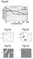
- Figure 4d shows the calculated transmission of a mirror as a function of deposited Sn layer thickness.
- Figure 4d shows two situations. In the first situation Sn is deposited on a Ru layer 4 (figure 3). In the second situation, Sn is deposited on Au top coating 8 (figures 4a-4c). For the Au/Sn alloy case (figure 4c), it is assumed that the Au/Sn alloy layer 14 is a homogeneous mixture of 100 nm Au and the Sn layer. It is observed that the Sn layer thickness is shown on a logarithmic scale.
- the Au/Sn top coating 14 will, in operation, be covered with Sn. So, care has to be taken that the deposited Sn will not result in an alloy which is too Sn rich, and that the deposited Sn is mixed with the Au, instead of remaining on top of the Au/Sn alloy layer 14.
- the mirror 3 can handle a certain amount of Sn to be deposited. This translates into the fact that the thickness of the Au/Sn alloy layer 14 where the transmission of the mirror 3 starts decreasing, which is about 20 nm in figure 4d, depends on the initial thickness of the Au layer 8. Increasing this initial thickness of the Au layer 8 results in more Sn absorption capacity.
- the Au layer may typically be in the range between 10 nm - 10 micron.
- a disadvantage of the Au/Sn alloy layer 14 is that the Sn vapor pressure for the Au/Sn alloy is lower than for pure Sn. Thus, removing the Sn from the Au/Sn alloy layer 14 requires a higher temperature than is needed to remove pure Sn from a surface. The fact that evaporation from the mirror surface results in slightly decreased Sn concentration at the upper surface of the Au/Sn alloy layer 14 will result in a higher reflectance since, then, a higher percentage of Au atoms will be present near this upper surface. This is beneficial with respect to non-interdiffusion combinations. In order to get more Sn into the vapor phase, it is also possible to add a halogen gas like Cl 2 , Br 2 or I 2 . The vapor pressure of metal-halides is usually higher than the vapor pressure for pure metals. So, adding a halogen gas enhances the evaporation process.
- the inventor of the present invention has calculated the effect of interdiffusion for two cases: (1) no interdiffusion combined with a high initial reflection (e.g., Ru) and (2) very high interdiffusion combined with a low initial reflection (e.g., Au).
- a Ru mirror is advantageous.
- the reflection of a Ru coated mirror drops quite dramatically for very thin Sn layers, as is already explained with reference to figure 4d.
- an Au coated mirror can maintain its initial transmission for a much longer period, as is also explained with reference to figure 4d.
- Other materials are expected to perform intermediately. For instance, Pd has a higher initial reflection than Au, however, Pd performs worse in interdiffusion.
- the present invention proposes to reduce the influence of Sn on the reflectance of the mirror in two ways: Firstly, keeping one or more parts of the reflecting mirror surface free from deposited Sn, such that incident EUV radiation on those parts is directly incident on Ru (or another good EUV reflector), and secondly removing the Sn from the surface.
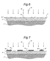
- the surface mobility of Sn on the mirror surface is increased by applying a protective coating 24 of for instance carbon (C) on top of the Ru (or other) layer 4, as shown in figure 6.
- This protective coating 24 can also be used for the reduction of chemical reactions of Ru (or other) layer 4 with Sn. Hence it prevents a Sn continuous film to be formed and helps keeping a large part of the Ru (or other) layer 4 clean.
- the protective coating 24 is selected from a material that is not easily wetted by Sn.
- growth (nucleation) sites are created artificially.
- the deposited Sn will gather on these nucleation sites during the nucleation stage. As shown in figure 7, this can, for instance, be done by depositing growth sites 28 of a predetermined material in the form of 'dots' on the Ru (or other) layer 4 in any desired density pattern that is suitable for illumination by EUV.
- Other possible nucleation sites are holes, trenches, lines, and other shapes.
- the growth sites 28 are preferably made of a material that is easily wetted by Sn, as, for instance, copper (Cu). They may be largely flat, line shaped or dot shaped.
- the deposited Sn then forms similarly shaped deposition sites 26 on top of the growth sites 28.
- the temperature of the Ru layer 4 is increased to increase the surface mobility of Sn on Ru layer 4. This will keep possible nucleation sites for the Sn incident on the mirror a larger distance apart. The Sn will be gathered at the nucleation sites, keeping a large part of the Ru layer 4 clean. Thereby, the overall transmission of the mirror remains on a higher level. This may, e.g., be done with the arrangement shown in figure 8.
- FIG 8 schematically shows a heat source 38 controlled by a controller 40.
- the heat source 38 may be connected to mirror 30(1) by connection parts 31.
- the connection parts 31 may be heat conductive.
- the controller 40 may be implemented as a suitably programmed computer, or a controller with suitable analogue and/or digital circuits.
- the heat source 38 generates heat, indicated with arrows 37, which is directed to a first mirror of 30(1) of radiation collector 50.
- the radiation collector 50 is shown to comprise a second mirror 30(2). As is known to persons skilled in the art, the radiation collector may comprise more than two mirrors to collect EUV radiation 35 and to produce projection beam 56.
- a cold unit 33 is provided, arranged opposite to the front surface of mirror 30(1), i.e., the surface of mirror 30(1) receiving EUV radiation 35.
- the cold unit 33 is termed "cold” since it is arranged outside the EUV radiation 35, i.e., in the shadow of mirror 30(2), and can, therefore, not be heated by EUV radiation 35.
- Dotted lines indicate how EUV radiation 35 is directed towards and reflected by mirror 30(1). These dotted lines also show that the cold unit 33 does not even receive EUV radiation reflected by mirror 30(1).
- Areas adjacent to cold unit 33 indicated with reference numerals 32, 34 are, thus, dark areas where no EUV radiation is present.
- Cold unit 33 may be attached to mirror 30(2), although it is preferred that no heat transfer from mirror 30(2) towards cold unit 33 occurs.
- Reference numerals 36 in mirrors 30(1) and 30(2) indicate possible through-holes.
- mirror 30(1) could be actively cooled, e.g., by a Peltier element connected to the rear surface of mirror 30(2).
- This Peltier element should have a cool surface towards mirror 30(1) and a heat removal side towards mirror 30(2), to cool mirror 30(1) and heat mirror 30(2).
- the heat produced by the heat source 38 heats Sn after being deposited on mirror 30(1), thus, stimulating evaporation 16 of Sn from the surface of mirror 30(1).
- the evaporated Sn is largely directed towards the cold unit 33 on which surface the evaporated Sn will condensate.
- the cold unit 33 may be replaced by a clean one.
- the cold unit 33 may be cleaned in-situ or ex-situ.
- An additional advantage of the set-up of figure 8 is that the mirror 30(1) is additionally cooled by the evaporation of the Sn.
- the other mirror 30(2) may be heated in a similar way and may face an other cold unit.
- Evaporated Sn may be pumped away by a pump 29 that is connected to and controlled by controller 40.
- the through-holes 36 are designed such that they have a capillary action for the Sn on the mirror surface, i.e., they collect Sn and transport it away to the rear mirror surface not receiving EUV radiation. To that effect, they may be provided with a wetting coating, e.g., made of Ag or Cu, to improve wetting by Sn, i.e. to arrange the surface in such a way that Sn, in the case it makes contact with the coating, spreads out over the entire surface of the coating. At the rear surface Sn sinks (not shown) may be provided.
- a wetting coating e.g., made of Ag or Cu
- capillary trenches 39 may be provided either on the front surface or on the rear surface or both, as shown in figure 9. These capillary trenches 39 collect Sn and transport Sn away, e.g., to the edge of the mirror where it may be collected by a Sn sink (not shown).
- the capillary trenches 39 may be connected to the through-holes 36 (if applied) such that Sn collected at the front side is transported to the rear side through the through-holes and from there transported to Sn sinks.
- halides may be introduced in the system in order to have more Sn containing vapor.
Landscapes
- Physics & Mathematics (AREA)
- Engineering & Computer Science (AREA)
- Epidemiology (AREA)
- Health & Medical Sciences (AREA)
- Public Health (AREA)
- Environmental & Geological Engineering (AREA)
- Atmospheric Sciences (AREA)
- Life Sciences & Earth Sciences (AREA)
- Plasma & Fusion (AREA)
- General Physics & Mathematics (AREA)
- Spectroscopy & Molecular Physics (AREA)
- General Engineering & Computer Science (AREA)
- High Energy & Nuclear Physics (AREA)
- Exposure Of Semiconductors, Excluding Electron Or Ion Beam Exposure (AREA)
- Exposure And Positioning Against Photoresist Photosensitive Materials (AREA)
- Optical Elements Other Than Lenses (AREA)
Priority Applications (1)
| Application Number | Priority Date | Filing Date | Title |
|---|---|---|---|
| EP04077836A EP1557844A3 (fr) | 2003-10-20 | 2004-10-13 | Utilisation d'une couche extérieure sur un mirroir pour un appareil lithographique, mirroir et appareil lithographique le comprenant et procédé de fabrication d'un composant |
Applications Claiming Priority (3)
| Application Number | Priority Date | Filing Date | Title |
|---|---|---|---|
| EP03078316 | 2003-10-20 | ||
| EP03078316A EP1526550A1 (fr) | 2003-10-20 | 2003-10-20 | Mirroir pour un appareil lithographique, appareil lithographique le comprenant et methode de fabrication d'un composant |
| EP04077836A EP1557844A3 (fr) | 2003-10-20 | 2004-10-13 | Utilisation d'une couche extérieure sur un mirroir pour un appareil lithographique, mirroir et appareil lithographique le comprenant et procédé de fabrication d'un composant |
Publications (2)
| Publication Number | Publication Date |
|---|---|
| EP1557844A2 true EP1557844A2 (fr) | 2005-07-27 |
| EP1557844A3 EP1557844A3 (fr) | 2006-03-01 |
Family
ID=34635339
Family Applications (1)
| Application Number | Title | Priority Date | Filing Date |
|---|---|---|---|
| EP04077836A Withdrawn EP1557844A3 (fr) | 2003-10-20 | 2004-10-13 | Utilisation d'une couche extérieure sur un mirroir pour un appareil lithographique, mirroir et appareil lithographique le comprenant et procédé de fabrication d'un composant |
Country Status (1)
| Country | Link |
|---|---|
| EP (1) | EP1557844A3 (fr) |
Family Cites Families (5)
| Publication number | Priority date | Publication date | Assignee | Title |
|---|---|---|---|---|
| US6541786B1 (en) * | 1997-05-12 | 2003-04-01 | Cymer, Inc. | Plasma pinch high energy with debris collector |
| US5958605A (en) * | 1997-11-10 | 1999-09-28 | Regents Of The University Of California | Passivating overcoat bilayer for multilayer reflective coatings for extreme ultraviolet lithography |
| US6285737B1 (en) * | 2000-01-21 | 2001-09-04 | Euv Llc | Condenser for extreme-UV lithography with discharge source |
| EP1333323A3 (fr) * | 2002-02-01 | 2004-10-06 | Nikon Corporation | Elément optique autonettoyant pour un système optique à rayons X, ainsi que des systèmes optiques et microlithographiques contenant cet élément |
| EP1348984A1 (fr) * | 2002-03-27 | 2003-10-01 | Carl Zeiss Semiconductor Manufacturing Technologies Ag | Element optique à large bande et procédé de sa production |
-
2004
- 2004-10-13 EP EP04077836A patent/EP1557844A3/fr not_active Withdrawn
Also Published As
| Publication number | Publication date |
|---|---|
| EP1557844A3 (fr) | 2006-03-01 |
Similar Documents
| Publication | Publication Date | Title |
|---|---|---|
| US7592610B2 (en) | Mirror for use in a lithographic apparatus, lithographic apparatus, device manufacturing method, and device manufactured thereby | |
| JP4404508B2 (ja) | リソグラフィ投影装置 | |
| TWI267704B (en) | Capping layer for EUV optical elements | |
| US20040165160A1 (en) | Lithographic apparatus and device manufacturing method | |
| JP3696201B2 (ja) | リソグラフィ装置およびデバイス製造方法 | |
| KR20020077521A (ko) | 조명 시스템, 리소그래피 투영 장치 및 디바이스 제조 방법 | |
| JP4469791B2 (ja) | 光学素子の保護方法およびデバイス製造方法 | |
| JP4799620B2 (ja) | 放射システムおよびリソグラフィ装置 | |
| TWI510821B (zh) | 光譜純度濾光器 | |
| JP4313328B2 (ja) | リソグラフィ装置、デバイス製造方法及び可変減衰器 | |
| JP2005020009A (ja) | リソグラフィ投影装置およびデバイス製造方法 | |
| JP4567659B2 (ja) | リソグフィ装置およびデバイス製造方法 | |
| TWI358616B (en) | Method for chemical reduction of an oxidized conta | |
| JP3662571B2 (ja) | リソグラフ装置およびデバイス製造方法 | |
| JP2002329649A (ja) | レチクル、レチクルの製造方法、露光装置及び露光方法 | |
| EP1557844A2 (fr) | Utilisation d'une couche extérieure sur un mirroir pour un appareil lithographique, mirroir et appareil lithographique le comprenant et procédé de fabrication d'un composant | |
| TWI278003B (en) | Lithographic apparatus and device manufacturing method | |
| US7235801B2 (en) | Grazing incidence mirror, lithographic apparatus including a grazing incidence mirror, method for providing a grazing incidence mirror, method for enhancing EUV reflection of a grazing incidence mirror, device manufacturing method and device manufactured thereby | |
| JP2004165642A (ja) | リソグラフィ装置およびデバイス製造方法 | |
| JP2002323599A (ja) | 多層膜反射鏡の製造方法及び露光装置 | |
| JP2008181760A (ja) | Euv光源、euv露光装置および半導体デバイスの製造方法 |
Legal Events
| Date | Code | Title | Description |
|---|---|---|---|
| PUAI | Public reference made under article 153(3) epc to a published international application that has entered the european phase |
Free format text: ORIGINAL CODE: 0009012 |
|
| AK | Designated contracting states |
Kind code of ref document: A2 Designated state(s): AT BE BG CH CY CZ DE DK EE ES FI FR GB GR HU IE IT LI LU MC NL PL PT RO SE SI SK TR |
|
| AX | Request for extension of the european patent |
Extension state: AL HR LT LV MK |
|
| PUAL | Search report despatched |
Free format text: ORIGINAL CODE: 0009013 |
|
| AK | Designated contracting states |
Kind code of ref document: A3 Designated state(s): AT BE BG CH CY CZ DE DK EE ES FI FR GB GR HU IE IT LI LU MC NL PL PT RO SE SI SK TR |
|
| AX | Request for extension of the european patent |
Extension state: AL HR LT LV MK |
|
| 17P | Request for examination filed |
Effective date: 20060602 |
|
| AKX | Designation fees paid |
Designated state(s): DE FR GB IT NL |
|
| 17Q | First examination report despatched |
Effective date: 20080701 |
|
| STAA | Information on the status of an ep patent application or granted ep patent |
Free format text: STATUS: THE APPLICATION IS DEEMED TO BE WITHDRAWN |
|
| 18D | Application deemed to be withdrawn |
Effective date: 20100504 |