EP1558026A2 - Système de caméra de vision nocturne pour véhicules, appareil et procédé d'affichage - Google Patents
Système de caméra de vision nocturne pour véhicules, appareil et procédé d'affichage Download PDFInfo
- Publication number
- EP1558026A2 EP1558026A2 EP05250092A EP05250092A EP1558026A2 EP 1558026 A2 EP1558026 A2 EP 1558026A2 EP 05250092 A EP05250092 A EP 05250092A EP 05250092 A EP05250092 A EP 05250092A EP 1558026 A2 EP1558026 A2 EP 1558026A2
- Authority
- EP
- European Patent Office
- Prior art keywords
- display
- night vision
- vehicle
- headlights
- vision image
- Prior art date
- Legal status (The legal status is an assumption and is not a legal conclusion. Google has not performed a legal analysis and makes no representation as to the accuracy of the status listed.)
- Granted
Links
Images

Classifications
-
- B—PERFORMING OPERATIONS; TRANSPORTING
- B60—VEHICLES IN GENERAL
- B60R—VEHICLES, VEHICLE FITTINGS, OR VEHICLE PARTS, NOT OTHERWISE PROVIDED FOR
- B60R1/00—Optical viewing arrangements; Real-time viewing arrangements for drivers or passengers using optical image capturing systems, e.g. cameras or video systems specially adapted for use in or on vehicles
- B60R1/20—Real-time viewing arrangements for drivers or passengers using optical image capturing systems, e.g. cameras or video systems specially adapted for use in or on vehicles
- B60R1/30—Real-time viewing arrangements for drivers or passengers using optical image capturing systems, e.g. cameras or video systems specially adapted for use in or on vehicles providing vision in the non-visible spectrum, e.g. night or infrared vision
-
- B—PERFORMING OPERATIONS; TRANSPORTING
- B60—VEHICLES IN GENERAL
- B60R—VEHICLES, VEHICLE FITTINGS, OR VEHICLE PARTS, NOT OTHERWISE PROVIDED FOR
- B60R1/00—Optical viewing arrangements; Real-time viewing arrangements for drivers or passengers using optical image capturing systems, e.g. cameras or video systems specially adapted for use in or on vehicles
- B60R1/20—Real-time viewing arrangements for drivers or passengers using optical image capturing systems, e.g. cameras or video systems specially adapted for use in or on vehicles
- B60R1/22—Real-time viewing arrangements for drivers or passengers using optical image capturing systems, e.g. cameras or video systems specially adapted for use in or on vehicles for viewing an area outside the vehicle, e.g. the exterior of the vehicle
- B60R1/23—Real-time viewing arrangements for drivers or passengers using optical image capturing systems, e.g. cameras or video systems specially adapted for use in or on vehicles for viewing an area outside the vehicle, e.g. the exterior of the vehicle with a predetermined field of view
- B60R1/24—Real-time viewing arrangements for drivers or passengers using optical image capturing systems, e.g. cameras or video systems specially adapted for use in or on vehicles for viewing an area outside the vehicle, e.g. the exterior of the vehicle with a predetermined field of view in front of the vehicle
-
- G—PHYSICS
- G02—OPTICS
- G02B—OPTICAL ELEMENTS, SYSTEMS OR APPARATUS
- G02B23/00—Telescopes, e.g. binoculars; Periscopes; Instruments for viewing the inside of hollow bodies; Viewfinders; Optical aiming or sighting devices
- G02B23/12—Telescopes, e.g. binoculars; Periscopes; Instruments for viewing the inside of hollow bodies; Viewfinders; Optical aiming or sighting devices with means for image conversion or intensification
-
- G—PHYSICS
- G02—OPTICS
- G02B—OPTICAL ELEMENTS, SYSTEMS OR APPARATUS
- G02B27/00—Optical systems or apparatus not provided for by any of the groups G02B1/00 - G02B26/00, G02B30/00
- G02B27/01—Head-up displays
-
- H—ELECTRICITY
- H04—ELECTRIC COMMUNICATION TECHNIQUE
- H04N—PICTORIAL COMMUNICATION, e.g. TELEVISION
- H04N7/00—Television systems
- H04N7/18—Closed-circuit television [CCTV] systems, i.e. systems in which the video signal is not broadcast
- H04N7/183—Closed-circuit television [CCTV] systems, i.e. systems in which the video signal is not broadcast for receiving images from a single remote source
-
- B—PERFORMING OPERATIONS; TRANSPORTING
- B60—VEHICLES IN GENERAL
- B60R—VEHICLES, VEHICLE FITTINGS, OR VEHICLE PARTS, NOT OTHERWISE PROVIDED FOR
- B60R2300/00—Details of viewing arrangements using cameras and displays, specially adapted for use in a vehicle
- B60R2300/10—Details of viewing arrangements using cameras and displays, specially adapted for use in a vehicle characterised by the type of camera system used
- B60R2300/101—Details of viewing arrangements using cameras and displays, specially adapted for use in a vehicle characterised by the type of camera system used using cameras with adjustable capturing direction
-
- B—PERFORMING OPERATIONS; TRANSPORTING
- B60—VEHICLES IN GENERAL
- B60R—VEHICLES, VEHICLE FITTINGS, OR VEHICLE PARTS, NOT OTHERWISE PROVIDED FOR
- B60R2300/00—Details of viewing arrangements using cameras and displays, specially adapted for use in a vehicle
- B60R2300/10—Details of viewing arrangements using cameras and displays, specially adapted for use in a vehicle characterised by the type of camera system used
- B60R2300/103—Details of viewing arrangements using cameras and displays, specially adapted for use in a vehicle characterised by the type of camera system used using camera systems provided with artificial illumination device, e.g. IR light source
-
- B—PERFORMING OPERATIONS; TRANSPORTING
- B60—VEHICLES IN GENERAL
- B60R—VEHICLES, VEHICLE FITTINGS, OR VEHICLE PARTS, NOT OTHERWISE PROVIDED FOR
- B60R2300/00—Details of viewing arrangements using cameras and displays, specially adapted for use in a vehicle
- B60R2300/10—Details of viewing arrangements using cameras and displays, specially adapted for use in a vehicle characterised by the type of camera system used
- B60R2300/106—Details of viewing arrangements using cameras and displays, specially adapted for use in a vehicle characterised by the type of camera system used using night vision cameras
-
- B—PERFORMING OPERATIONS; TRANSPORTING
- B60—VEHICLES IN GENERAL
- B60R—VEHICLES, VEHICLE FITTINGS, OR VEHICLE PARTS, NOT OTHERWISE PROVIDED FOR
- B60R2300/00—Details of viewing arrangements using cameras and displays, specially adapted for use in a vehicle
- B60R2300/20—Details of viewing arrangements using cameras and displays, specially adapted for use in a vehicle characterised by the type of display used
- B60R2300/205—Details of viewing arrangements using cameras and displays, specially adapted for use in a vehicle characterised by the type of display used using a head-up display
-
- B—PERFORMING OPERATIONS; TRANSPORTING
- B60—VEHICLES IN GENERAL
- B60R—VEHICLES, VEHICLE FITTINGS, OR VEHICLE PARTS, NOT OTHERWISE PROVIDED FOR
- B60R2300/00—Details of viewing arrangements using cameras and displays, specially adapted for use in a vehicle
- B60R2300/30—Details of viewing arrangements using cameras and displays, specially adapted for use in a vehicle characterised by the type of image processing
-
- B—PERFORMING OPERATIONS; TRANSPORTING
- B60—VEHICLES IN GENERAL
- B60R—VEHICLES, VEHICLE FITTINGS, OR VEHICLE PARTS, NOT OTHERWISE PROVIDED FOR
- B60R2300/00—Details of viewing arrangements using cameras and displays, specially adapted for use in a vehicle
- B60R2300/80—Details of viewing arrangements using cameras and displays, specially adapted for use in a vehicle characterised by the intended use of the viewing arrangement
- B60R2300/8053—Details of viewing arrangements using cameras and displays, specially adapted for use in a vehicle characterised by the intended use of the viewing arrangement for bad weather conditions or night vision
-
- G—PHYSICS
- G02—OPTICS
- G02B—OPTICAL ELEMENTS, SYSTEMS OR APPARATUS
- G02B27/00—Optical systems or apparatus not provided for by any of the groups G02B1/00 - G02B26/00, G02B30/00
- G02B27/01—Head-up displays
- G02B27/0101—Head-up displays characterised by optical features
- G02B2027/0138—Head-up displays characterised by optical features comprising image capture systems, e.g. camera
-
- G—PHYSICS
- G02—OPTICS
- G02B—OPTICAL ELEMENTS, SYSTEMS OR APPARATUS
- G02B27/00—Optical systems or apparatus not provided for by any of the groups G02B1/00 - G02B26/00, G02B30/00
- G02B27/01—Head-up displays
- G02B27/0101—Head-up displays characterised by optical features
- G02B2027/014—Head-up displays characterised by optical features comprising information/image processing systems
Definitions
- the present invention relates to an on-vehicle night vision camera system, a display device and a display method, to be adopted to display at a display means an image of the area ahead of the vehicle photographed with an infrared camera.
- the display at the head-up display unit does not change even when the headlights of the vehicle are set to high beams in order to check the area ahead of the vehicle over a longer range, a satisfactory level of long-range visibility may not always be assured in the system in the related art.
- An on-vehicle night vision camera system includes an infrared camera which photographs an area ahead of the vehicle, a display means for displaying a night vision image photographed with the infrared camera, a headlight state detection means for detecting a high beam setting of headlights of the vehicle and a display state change means for changing a display state of the night vision image displayed at the display means when the headlight state detection means detects that the headlights have been switched to the high beam setting.
- a display device at which the night vision image photographed with an infrared camera used to photograph an area ahead of a vehicle is displayed includes an input means for inputting a signal indicating that headlights of the vehicle have been switched to high beams is input and a display control means for changing a display state of the night vision image when the signal indicating the high beam setting of the headlights is input to the input means.
- a display method for displaying at a display means a night vision image photographed with an infrared camera used to photograph an area ahead of a vehicle, a high beam setting of headlights at the vehicle is detected and a display state of the night vision image displayed at the display means is changed if the headlights are detected to have been switched to the high beam setting.
- FIG. 1 shows a vehicle having installed therein the on-vehicle night vision camera system achieved in an embodiment.
- FIG. 2 is a block diagram of the on-vehicle night vision camera system achieved in the embodiment.
- the on-vehicle night vision camera system in the embodiment comprises an infrared camera 1, an electronic control unit 2 (hereafter referred to as an ECU 2), a head-up display (HUD) 3, infrared projectors 4R and 4L, a high beam display control switch 5,and a high beam switch 6.
- ECU 2 electronice control unit 2
- HUD head-up display
- the infrared camera 1 mounted at the top of the front windshield, photographs the area ahead of the vehicle. As the infrared camera 1 receives near-infrared light having a wavelength that is not visible to the human eye, it is able to photograph people and objects at night.
- the infrared projectors 4R and 4L which may be mounted at, for instance, the front bumper, project the near-infrared light along the forward direction relative to the vehicle so as to enable the infrared camera 1 to photograph an image ahead of the vehicle.
- At the head-up display 3 installed at the front windshield and positioned so that a display thereupon can be visually checked by the driver with ease, at least the image (night vision image) photographed with the infrared camera 1 is displayed.
- the headlights (headlamps) of the vehicle can be switched to a high beam position or a low beam position with a light switch (not shown).
- the high beam switch 6 enters an ON state as the headlights are switched to the high beam setting and enters an OFF state as the headlights are switched to the low beam setting.
- the ECU 2 includes a CPU 2a, a ROM 2b and a RAM 2c.
- the ECU 2 changes the display state of the night vision image displayed at the head-up display 3, i . e . , the image captured with the infrared camera 1 for a following method, when the high beam switch 6 is turned on.
- the high beam display control switch 5 is operated by the driver to switch to a zoom display or a blank display.
- the ECU 2 executes digital zoom processing on the night vision image. As a result, the night vision image is displayed in an enlargement at the head-up display 3.
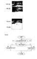
- FIGS. 3A and 3B respectively show a regular-size night vision image and an enlarged night vision image on display.
- FIG. 3A shows a night vision image photographed with the infrared camera 1.
- the image in FIG. 3A is a normal image that has not undergone the digital zoom processing.
- the white area at the center of the display screen in FIG. 3A is a person.
- FIG. 3B shows an image achieved by executing the zoom processing on the image shown in FIG. 3A.
- the person at the center of the screen in FIG. 3A is enlarged in the display shown in FIG. 3B.
- an area over a longer range ahead of the vehicle can be displayed in an enlargement. Namely, an image satisfying the need of the driver to check for objects far ahead of the vehicle can be displayed.
- FIG. 4A shows an example of a night vision image that may be displayed at the head-up display 3
- FIG. 4B shows a blank screen achieved by erasing the night vision image in FIG. 4A.
- Some drivers may prefer to check the area far ahead of the vehicle with their own eyes with the headlights switched to the high beam setting. With the night vision image on the head-up display 3 erased, such a driver is able to check the area ahead of the vehicle through the windshield with ease.
- the ECU 2 changes the display state of the night vision image displayed at the head-up display 3 to allow the driver to check the area far ahead of the vehicle when the high beam switch 6 is turned on.
- FIG. 5 presents a flowchart of the processing executed in the on-vehicle night vision camera system in the embodiment.
- the processing which starts in step S10, is executed by the CPU 2a in the ECU 2.
- step S10 a decision is made as to whether or not the high beam switch 6 has been turned on based upon a signal input from the high beam switch 6. If it is decided that the high beam switch 6 has been turned on, the operation proceeds to step S20, whereas if it is decided that the high beam switch 6 has not been turned on, the operation waits in standby in step S10.
- step S20 a decision is made as to whether or not the high beam display control switch 5 is currently set to the zoom display based upon a signal input from the high beam display control switch 5.
- the operation proceeds to step S30 if it is decided that the high beam display control switch 5 is currently set to the zoom display, whereas the operation proceeds to step S40 if it is decided that the high beam display control switch 5 is currently set to the blank display.
- step S30 digital zoom processing is executed on the central area of the night vision image photographed with the infrared camera 1 and an image containing an enlarged front area is displayed at the head-up display 3.
- step S40 on the other hand, no night vision image is displayed at the head-up display 3. Namely, if a night vision image is currently displayed at the head-up display 3, processing is executed to erase the image on display.
- step S30 or in step S40 the operation returns to step S10. Subsequently, the processing, which starts in step S10, is repeatedly executed.
- the display state in which the night vision image photographed with the infrared camera displayed at the head-up display is changed in the on-vehicle night vision camera system in the embodiment.
- an image satisfying the need of the driver to check the field far ahead can be displayed at the head-up display.
- the night vision image photographed with the infrared camera is displayed in an enlargement at the head-up display in the on-vehicle night vision camera system in the embodiment to allow the driver to check the image of the field far ahead on the head-up display.
- the on-vehicle night vision camera system in the embodiment provides an option of not having any night vision image displayed at the head-up display when the headlights of the vehicle are switched to high beams (to the high beam setting) .
- This option allows the driver to easily check with his own eyes the area far ahead irradiated with visible light by the high beams.
- the night vision image photographed with the infrared camera may be displayed at a display device such as an in-vehicle monitor used in conjunction with a car navigation system, instead of at a head-up display.
- the control device may be built into the display device so as to change the display state of the night vision image in response to a signal indicating that the headlights of the vehicle have been set to high beams input to the display device.
- the present invention may be adopted in conjunction with headlights whose range can be switched over multiple stages, i.e., three stages or more. Namely, when such headlights are set to high beams to irradiate the field further ahead, the display state of the night vision image displayed at the display device such as a head-up display should be adjusted.
- the central area of the night vision image photographed with the infrared camera 1 is enlarged when displaying an enlarged night vision image in the on-vehicle night vision camera system in the embodiment, an area other than the central area of the image may be enlarged.
- the ECU 2 may execute image processing on the photographed image, identify any person in the image and then enlarge the portion of the image over which the identified person is photographed.
- digital zoom processing is executed in order to display the enlarged image, an image obtained by photographing the area far ahead with a zoom lens may instead be displayed.
- the display may be, for instance, darkened to an extent substantially equivalent to the state of blank display so as to make the image substantially invisible to the driver. Namely, with the night vision image at the head-up display eliminated from the field of view of the driver, the driver is able to focus on the area ahead of the vehicle irradiated with high beams.
- the on-vehicle night vision camera system may include another setting "normal display” at which the display state is not switched.
- the display state of the night vision image displayed on the head-up display 3 remains unchanged even when the headlights are switched to the high beam setting. Namely, the initial night vision image photographed with the infrared camera 1 remains on display at the head-up display 3.
Landscapes
- Engineering & Computer Science (AREA)
- Physics & Mathematics (AREA)
- Multimedia (AREA)
- General Physics & Mathematics (AREA)
- Optics & Photonics (AREA)
- Mechanical Engineering (AREA)
- Astronomy & Astrophysics (AREA)
- Signal Processing (AREA)
- Closed-Circuit Television Systems (AREA)
- Studio Devices (AREA)
- Controls And Circuits For Display Device (AREA)
- Instrument Panels (AREA)
Applications Claiming Priority (2)
| Application Number | Priority Date | Filing Date | Title |
|---|---|---|---|
| JP2004015458A JP3982504B2 (ja) | 2004-01-23 | 2004-01-23 | 車両用暗視カメラ装置および表示装置 |
| JP2004015458 | 2004-01-23 |
Publications (3)
| Publication Number | Publication Date |
|---|---|
| EP1558026A2 true EP1558026A2 (fr) | 2005-07-27 |
| EP1558026A3 EP1558026A3 (fr) | 2005-08-03 |
| EP1558026B1 EP1558026B1 (fr) | 2006-10-18 |
Family
ID=34631942
Family Applications (1)
| Application Number | Title | Priority Date | Filing Date |
|---|---|---|---|
| EP05250092A Expired - Lifetime EP1558026B1 (fr) | 2004-01-23 | 2005-01-11 | Système de caméra de vision nocturne pour véhicules, appareil et procédé d'affichage |
Country Status (5)
| Country | Link |
|---|---|
| US (1) | US7078692B2 (fr) |
| EP (1) | EP1558026B1 (fr) |
| JP (1) | JP3982504B2 (fr) |
| CN (1) | CN100413324C (fr) |
| DE (1) | DE602005000175T2 (fr) |
Cited By (1)
| Publication number | Priority date | Publication date | Assignee | Title |
|---|---|---|---|---|
| EP1912157A1 (fr) * | 2006-10-09 | 2008-04-16 | MAGNETI MARELLI SISTEMI ELETTRONICI S.p.A. | Système de traitement d'images numériques pour représenter automatiquement des scènes environnantes pour le conducteur d'un véhicule à des fins d'assistance à la conduite, et procédé de fonctionnement correspondant |
Families Citing this family (22)
| Publication number | Priority date | Publication date | Assignee | Title |
|---|---|---|---|---|
| JP4218670B2 (ja) * | 2005-09-27 | 2009-02-04 | オムロン株式会社 | 前方撮影装置 |
| JP4389173B2 (ja) * | 2005-12-08 | 2009-12-24 | 株式会社デンソー | 車両用表示装置 |
| DE102007043304B3 (de) * | 2007-09-11 | 2009-02-19 | Daimler Ag | Verfahren und Vorrichtung zum Betreiben eines Fahrzeuges |
| BRPI0722256A2 (pt) * | 2007-11-05 | 2014-04-01 | Volvo Lastvagnar Ab | Disposição de visão noturna baseada em veículo e método para operação da mesma. |
| JP5157663B2 (ja) * | 2008-06-13 | 2013-03-06 | 株式会社デンソー | 車両用表示装置 |
| JP5198346B2 (ja) | 2009-04-23 | 2013-05-15 | 本田技研工業株式会社 | 車両周辺監視装置 |
| DE102009035743A1 (de) * | 2009-08-01 | 2011-02-17 | Automotive Lighting Reutlingen Gmbh | Lichtmodul für einen Kraftfahrzeugscheinwerfer |
| JP4952765B2 (ja) * | 2009-10-21 | 2012-06-13 | トヨタ自動車株式会社 | 車両用夜間視界支援装置 |
| US9001212B2 (en) * | 2010-03-11 | 2015-04-07 | Flir Systems, Inc. | Infrared transmissive dome systems and methods |
| US8905311B2 (en) * | 2010-03-11 | 2014-12-09 | Flir Systems, Inc. | Infrared camera with infrared-transmissive dome systems and methods |
| TWI489139B (zh) * | 2013-02-05 | 2015-06-21 | 南臺科技大學 | 交通工具之抬頭顯示設備 |
| CN103395393B (zh) * | 2013-08-13 | 2016-03-16 | 北京汽车研究总院有限公司 | 一种汽车前风挡投影系统及汽车 |
| CN104554003B (zh) * | 2013-10-15 | 2017-11-07 | 长春威视追光科技有限责任公司 | 智能车载悬挂式夜视平视显示器 |
| KR101500238B1 (ko) * | 2013-12-23 | 2015-03-06 | 현대자동차주식회사 | 차량용 헤드업 디스플레이 조명 표시 방법 |
| CN104590117A (zh) * | 2014-11-27 | 2015-05-06 | 张金茂 | 汽车倒车电子保安装置 |
| US9168869B1 (en) * | 2014-12-29 | 2015-10-27 | Sami Yaseen Kamal | Vehicle with a multi-function auxiliary control system and heads-up display |
| JP2016182911A (ja) * | 2015-03-26 | 2016-10-20 | 日本電産コパル株式会社 | 車両用の視認補助装置および車両 |
| MY194747A (en) * | 2016-04-20 | 2022-12-15 | Nissan Motor | Information display method and display control device |
| JP6793193B2 (ja) * | 2016-06-29 | 2020-12-02 | 京セラ株式会社 | 物体検出表示装置、移動体及び物体検出表示方法 |
| KR102256384B1 (ko) * | 2016-11-01 | 2021-05-25 | 스미토모 겐키 가부시키가이샤 | 작업기계용 주변감시시스템 |
| JP6912757B2 (ja) * | 2017-09-08 | 2021-08-04 | 三菱自動車工業株式会社 | 車両の前照灯制御装置 |
| CN113253455B (zh) * | 2021-04-06 | 2022-11-15 | 东风汽车集团股份有限公司 | 一种自动变道ar-hud显示系统及使用方法 |
Family Cites Families (7)
| Publication number | Priority date | Publication date | Assignee | Title |
|---|---|---|---|---|
| CN1126969C (zh) * | 1999-03-08 | 2003-11-05 | 戴巍 | 机动车夜视装置 |
| WO2002005013A2 (fr) * | 2000-07-10 | 2002-01-17 | Ophir Optronics Ltd. | Procede et systeme d'assistance a la visibilite reduite |
| SE519864C2 (sv) * | 2000-10-26 | 2003-04-15 | Autoliv Dev | Anordning för förbättring av mörkersikten hos ett fordon såsom en bil |
| JP2003016429A (ja) * | 2001-06-28 | 2003-01-17 | Honda Motor Co Ltd | 車両周辺監視装置 |
| JP2003075893A (ja) * | 2001-09-06 | 2003-03-12 | Murakami Corp | 車両用周囲撮像装置 |
| JP2004058828A (ja) * | 2002-07-29 | 2004-02-26 | Denso Corp | 車両前方表示システム |
| US6967569B2 (en) * | 2003-10-27 | 2005-11-22 | Ford Global Technologies Llc | Active night vision with adaptive imaging |
-
2004
- 2004-01-23 JP JP2004015458A patent/JP3982504B2/ja not_active Expired - Lifetime
-
2005
- 2005-01-11 EP EP05250092A patent/EP1558026B1/fr not_active Expired - Lifetime
- 2005-01-11 DE DE602005000175T patent/DE602005000175T2/de not_active Expired - Lifetime
- 2005-01-14 US US11/034,974 patent/US7078692B2/en not_active Expired - Fee Related
- 2005-01-21 CN CNB200510005614XA patent/CN100413324C/zh not_active Expired - Fee Related
Cited By (1)
| Publication number | Priority date | Publication date | Assignee | Title |
|---|---|---|---|---|
| EP1912157A1 (fr) * | 2006-10-09 | 2008-04-16 | MAGNETI MARELLI SISTEMI ELETTRONICI S.p.A. | Système de traitement d'images numériques pour représenter automatiquement des scènes environnantes pour le conducteur d'un véhicule à des fins d'assistance à la conduite, et procédé de fonctionnement correspondant |
Also Published As
| Publication number | Publication date |
|---|---|
| CN1645915A (zh) | 2005-07-27 |
| US20060043295A1 (en) | 2006-03-02 |
| EP1558026B1 (fr) | 2006-10-18 |
| JP2005206057A (ja) | 2005-08-04 |
| CN100413324C (zh) | 2008-08-20 |
| JP3982504B2 (ja) | 2007-09-26 |
| US7078692B2 (en) | 2006-07-18 |
| DE602005000175D1 (de) | 2006-11-30 |
| EP1558026A3 (fr) | 2005-08-03 |
| DE602005000175T2 (de) | 2007-08-30 |
Similar Documents
| Publication | Publication Date | Title |
|---|---|---|
| US7078692B2 (en) | On-vehicle night vision camera system, display device and display method | |
| CN108621937B (zh) | 车载显示设备、车载显示设备的控制方法以及存储车载显示设备的控制程序的存储介质 | |
| DE10261291B4 (de) | Anzeigeeinrichtung für ein Fahrzeug | |
| JP2005182306A (ja) | 車両用表示装置 | |
| JP2003081014A (ja) | 車両周辺監視装置 | |
| CN106537905A (zh) | 信号处理设备、信号处理方法和监视系统 | |
| US20100265345A1 (en) | Vehicle based night-vision arrangement and method for operating the same | |
| CN115210099B (zh) | 信息处理装置、车辆及信息处理方法 | |
| JP2010130647A (ja) | 車両周辺確認装置 | |
| CN113924518A (zh) | 控制机动车的增强现实平视显示器装置的显示内容 | |
| JP2025168437A (ja) | 撮影装置、制御方法、プログラム及び記憶媒体 | |
| JP2006219000A (ja) | 車両用操作装置 | |
| JP4687573B2 (ja) | 車両用運転支援装置 | |
| JP7576064B2 (ja) | 車両用表示装置 | |
| CN111497745B (zh) | 显示系统、行驶控制装置、显示控制方法以及存储介质 | |
| JP2019159216A (ja) | 車載表示装置、車載表示装置を制御する方法及びコンピュータプログラム | |
| JP2008018760A (ja) | 運転支援装置 | |
| CN119452672A (zh) | 用于在机动车中协调地显示摄像头图像的方法和相应设置的机动车 | |
| JP7073237B2 (ja) | 画像表示装置、画像表示方法 | |
| US20210009037A1 (en) | Vehicle sighting device, and method of setting angle of view of imaging section of vehicle sighting device | |
| JP4033170B2 (ja) | 車両用表示装置 | |
| JP2021172243A (ja) | 後方確認支援システム | |
| JP7331731B2 (ja) | 車両用電子ミラーシステム | |
| JP2024112137A (ja) | 表示制御装置、表示制御方法、及びプログラム | |
| JP7636113B2 (ja) | 映像表示システム |
Legal Events
| Date | Code | Title | Description |
|---|---|---|---|
| PUAI | Public reference made under article 153(3) epc to a published international application that has entered the european phase |
Free format text: ORIGINAL CODE: 0009012 |
|
| PUAL | Search report despatched |
Free format text: ORIGINAL CODE: 0009013 |
|
| 17P | Request for examination filed |
Effective date: 20050126 |
|
| AK | Designated contracting states |
Kind code of ref document: A2 Designated state(s): AT BE BG CH CY CZ DE DK EE ES FI FR GB GR HU IE IS IT LI LT LU MC NL PL PT RO SE SI SK TR |
|
| AX | Request for extension of the european patent |
Extension state: AL BA HR LV MK YU |
|
| AK | Designated contracting states |
Kind code of ref document: A3 Designated state(s): AT BE BG CH CY CZ DE DK EE ES FI FR GB GR HU IE IS IT LI LT LU MC NL PL PT RO SE SI SK TR |
|
| AX | Request for extension of the european patent |
Extension state: AL BA HR LV MK YU |
|
| RIC1 | Information provided on ipc code assigned before grant |
Ipc: 7H 04N 7/18 A |
|
| GRAP | Despatch of communication of intention to grant a patent |
Free format text: ORIGINAL CODE: EPIDOSNIGR1 |
|
| AKX | Designation fees paid |
Designated state(s): DE FR GB |
|
| GRAS | Grant fee paid |
Free format text: ORIGINAL CODE: EPIDOSNIGR3 |
|
| GRAA | (expected) grant |
Free format text: ORIGINAL CODE: 0009210 |
|
| RAP1 | Party data changed (applicant data changed or rights of an application transferred) |
Owner name: NISSAN MOTOR COMPANY LIMITED |
|
| AK | Designated contracting states |
Kind code of ref document: B1 Designated state(s): DE FR GB |
|
| REG | Reference to a national code |
Ref country code: GB Ref legal event code: FG4D |
|
| REF | Corresponds to: |
Ref document number: 602005000175 Country of ref document: DE Date of ref document: 20061130 Kind code of ref document: P |
|
| ET | Fr: translation filed | ||
| PLBE | No opposition filed within time limit |
Free format text: ORIGINAL CODE: 0009261 |
|
| STAA | Information on the status of an ep patent application or granted ep patent |
Free format text: STATUS: NO OPPOSITION FILED WITHIN TIME LIMIT |
|
| 26N | No opposition filed |
Effective date: 20070719 |
|
| PGFP | Annual fee paid to national office [announced via postgrant information from national office to epo] |
Ref country code: FR Payment date: 20100208 Year of fee payment: 6 |
|
| PGFP | Annual fee paid to national office [announced via postgrant information from national office to epo] |
Ref country code: DE Payment date: 20100107 Year of fee payment: 6 Ref country code: GB Payment date: 20100106 Year of fee payment: 6 |
|
| GBPC | Gb: european patent ceased through non-payment of renewal fee |
Effective date: 20110111 |
|
| REG | Reference to a national code |
Ref country code: FR Ref legal event code: ST Effective date: 20110930 |
|
| PG25 | Lapsed in a contracting state [announced via postgrant information from national office to epo] |
Ref country code: FR Free format text: LAPSE BECAUSE OF NON-PAYMENT OF DUE FEES Effective date: 20110131 |
|
| PG25 | Lapsed in a contracting state [announced via postgrant information from national office to epo] |
Ref country code: GB Free format text: LAPSE BECAUSE OF NON-PAYMENT OF DUE FEES Effective date: 20110111 |
|
| REG | Reference to a national code |
Ref country code: DE Ref legal event code: R119 Ref document number: 602005000175 Country of ref document: DE Effective date: 20110802 |
|
| PG25 | Lapsed in a contracting state [announced via postgrant information from national office to epo] |
Ref country code: DE Free format text: LAPSE BECAUSE OF NON-PAYMENT OF DUE FEES Effective date: 20110802 |