EP1558035A1 - Übertragungssystem und -verfahren in Satelliten-Hausverteilungsanlagen - Google Patents
Übertragungssystem und -verfahren in Satelliten-Hausverteilungsanlagen Download PDFInfo
- Publication number
- EP1558035A1 EP1558035A1 EP05290076A EP05290076A EP1558035A1 EP 1558035 A1 EP1558035 A1 EP 1558035A1 EP 05290076 A EP05290076 A EP 05290076A EP 05290076 A EP05290076 A EP 05290076A EP 1558035 A1 EP1558035 A1 EP 1558035A1
- Authority
- EP
- European Patent Office
- Prior art keywords
- signal
- processing unit
- bis
- satellite
- entity
- Prior art date
- Legal status (The legal status is an assumption and is not a legal conclusion. Google has not performed a legal analysis and makes no representation as to the accuracy of the status listed.)
- Granted
Links
- 238000009434 installation Methods 0.000 title claims abstract description 32
- 238000000034 method Methods 0.000 title claims abstract description 21
- 238000009826 distribution Methods 0.000 claims abstract description 56
- 230000005540 biological transmission Effects 0.000 claims abstract description 23
- 239000011159 matrix material Substances 0.000 claims description 21
- 238000007781 pre-processing Methods 0.000 claims description 7
- 230000008569 process Effects 0.000 claims description 7
- 238000001914 filtration Methods 0.000 claims description 5
- 230000008878 coupling Effects 0.000 claims description 2
- 238000010168 coupling process Methods 0.000 claims description 2
- 238000005859 coupling reaction Methods 0.000 claims description 2
- 230000006870 function Effects 0.000 description 20
- 230000010287 polarization Effects 0.000 description 12
- 230000000875 corresponding effect Effects 0.000 description 10
- 238000010586 diagram Methods 0.000 description 6
- 230000008054 signal transmission Effects 0.000 description 5
- 230000008901 benefit Effects 0.000 description 3
- 238000001228 spectrum Methods 0.000 description 3
- 238000003860 storage Methods 0.000 description 2
- 241000861223 Issus Species 0.000 description 1
- 230000008859 change Effects 0.000 description 1
- 230000002596 correlated effect Effects 0.000 description 1
- 238000005388 cross polarization Methods 0.000 description 1
- 230000000694 effects Effects 0.000 description 1
- 239000000284 extract Substances 0.000 description 1
- 239000004744 fabric Substances 0.000 description 1
- 238000012423 maintenance Methods 0.000 description 1
- 238000004519 manufacturing process Methods 0.000 description 1
- 239000000203 mixture Substances 0.000 description 1
Images





Classifications
-
- H—ELECTRICITY
- H04—ELECTRIC COMMUNICATION TECHNIQUE
- H04H—BROADCAST COMMUNICATION
- H04H40/00—Arrangements specially adapted for receiving broadcast information
- H04H40/18—Arrangements characterised by circuits or components specially adapted for receiving
- H04H40/27—Arrangements characterised by circuits or components specially adapted for receiving specially adapted for broadcast systems covered by groups H04H20/53 - H04H20/95
- H04H40/90—Arrangements characterised by circuits or components specially adapted for receiving specially adapted for broadcast systems covered by groups H04H20/53 - H04H20/95 specially adapted for satellite broadcast receiving
-
- H—ELECTRICITY
- H04—ELECTRIC COMMUNICATION TECHNIQUE
- H04N—PICTORIAL COMMUNICATION, e.g. TELEVISION
- H04N7/00—Television systems
- H04N7/10—Adaptations for transmission by electrical cable
- H04N7/102—Circuits therefor, e.g. noise reducers, equalisers, amplifiers
- H04N7/104—Switchers or splitters
Definitions
- the present invention relates to receiving installations satellite with several processing units, still called enclosures (box in English), and relates more particularly to the exchange of data between these processing units.
- satellite reception facilities The field of satellite reception facilities is in full swing boom in recent years.
- the market for video devices in all genre has taken on a great many homes have a satellite reception facility comprising several processing units, or box (box in English) distributed in different rooms of the family home.
- the processing units are all connected to a head of single receipt, also called LNB (Low Noise Block) downconverter ”) or more simply referred to as receiver satellite in the present description.
- LNB Low Noise Block
- FIG. 1 illustrates the configuration of an installation of the aforementioned type comprising three processing units respectively 213, 214 and 215.
- a initial satellite signal 1 is reflected and focused by a satellite dish 2 to be redirected to a receiver 3.
- Output ports 4, 5 and 6 of the receiver connected respectively to the processing units 213, 214 and 215 via coaxial cables 216, 217 and 218.
- the receiver 3 first of all carries out a selecting one of several signals included in the initial signal, before performing preprocessing on each selected signal. Signals pretreated are then switched by a switching matrix to be transmitted via the coaxial cables 216, 217 and 218 to the processing units 213, 214 and 215.
- the term "signal" refers to an RF signal in the present description.
- satellite reception based on the functions of a conventional receiver.
- One of the first functions of the receiver 3 is to collect the satellite signals.
- a satellite signal is usually broadcast in two cross polarizations, the two polarizations being linear, that is to say horizontal and vertical, or circular, that is left and right.
- a conventional receiver usually comprises two antennas, a first to collect horizontal polarization signals, respectively left, and a second antenna to collect the polarization signals vertical, respectively right.
- the receiver makes a first selection among a first horizontal polarization signal, respectively left and a second vertical polarization signal, respectively right. Then, the receiver amplifies the signal so selected with the smallest noise factor possible.
- the satellite signal 1 is received by the receiver 3 in an initial frequency band between 10.7 GHz and 12.75 GHz. This frequency band is too high to be transmitted directly to a processing unit. It is therefore lowered by the receiver 3 in the BIS compatible with the capabilities of the processing units.
- the BIS is between about 950 MHz and about 2150 MHz.
- BIS can also be between about 950 MHz and about 1450 MHz.
- a satellite signal of linear polarizations and a BIS between 950 MHz and 2150 MHz are taken as an example in the remainder of the description.
- the band initial frequency is divided into two parts: a frequency band initial low and an initial high frequency band. So the receiver makes a second selection from a modulated signal in the band of low frequency and a modulated signal in the high band. At the end of this second selection, the receiver selects one of the four signals from initial satellite signal.
- the spectrum of these four signals is represented schematically in Figure 1a, where by convention, spectra of vertical or horizontal polarization are shown respectively below or above the frequency axis.
- the receiver performs a preprocessing of the selected signal before switch it via a switching matrix.
- This pretreatment consists of mix the frequency of the previously selected signal with a predetermined mixing frequency in order to obtain a pre-processed signal in the BIS.
- the predetermined mixing frequency generally used to treat the initial low frequency band is typically 9.75 GHz and that to process the high initial frequency band is typically 10.6 GHz.
- the receiver 3 thus provides four signals, respectively from the pre-processed VeBa, VeHa, HoBa and HoHa signals which are selectively transposed into BIS.
- Figure 1a illustrates the four signals VeBa, VeHa, HoBa and HoHa respectively referenced 201, 202, 203 and 204 which are included in the satellite external initial signal.
- the coaxial cables referenced 216, 217 and 218 carry each at most one of the pretreated signals described above, the same signal being of course be transported on several cables.
- a microcontroller manages a switching matrix according to commands received from the processing units to transmit a pre-processed signal determined to at least one respective processing unit.
- a switching matrix is built into the receiver. However, in some installations the switching matrix is part of another box connected to the receiver.
- Each processing unit is responsible for processing one or more "useful" signals extracted from the pre-processed signal transmitted by the coaxial cable connecting to the receiver 3.
- a "wanted signal” is a signal corresponding to a given satellite channel.
- the processing units are independent of one another and do not exchange information with each other.
- these units of may offer different functions such as a function recording of digital data of video or film type on a medium of mass storage, a data reading function thus recorded, a function enabling them to be connected to the telephone network, a function of management of the rights of decoding ...
- the present invention aims to propose a solution to satisfy this need.
- a second aspect of the present invention proposes an entity of distribution to implement the method described in the first aspect.
- a third aspect of the invention provides a system for putting the process described in the first aspect.
- a fourth aspect of the invention proposes a processing unit intended for use in a distribution system according to the third aspect within a satellite reception facility comprising a satellite receiver and a signal distribution entity.
- the processing unit is connected to the distribution entity via a link wired and includes means for processing a received signal, in the band UHF frequency called Satellite Intermediate Band or BIS, via the link Wired.
- the unit of processing further comprises a suitable signal modulation unit to modulate a signal in the BIS, and to transmit the signal as well modulated to the distribution entity via the wire link.
- the processing unit may comprise a modulation unit of signal adapted to modulate a signal in a distinct frequency band of and substantially adjacent to the BIS and to transmit the signal as well modulated to the distribution entity via the wire link.
- a unit of treatment is a set top box.
- the same references designate identical or similar elements.
- the term “External signal” refers to a signal received from outside the facility satellite reception, that is to say a satellite signal or a signal from a signal
- the term “internal signal” refers to a signal produced and transmitted within the satellite reception facility
- the term of "Internal connection” refers to a connection to transmit to one or more processing units an internal signal emitted by a unit of treatment in a frequency included in the BIS.
- a receiver comprises a functional block of preprocessing 205 which receives as input the external signals VeBa, Ve Ha, HoBa and HoHa respectively referenced 201, 202, 203 and 204 from the initial signal external satellite 1.
- the signal thus received is pre-processed by the functional block of preprocessing 205 before being transmitted to a signal distribution entity 207.
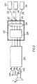
- Entity 207 may be included in the receiver or simply be connected. It receives as input a preprocessed signal. It includes a matrix 208 and connection means 209 for coupling outputs from the switch fabric to the entity's referenced ports 210, 211, and 212 207. Entity 207 is thus adapted to be able to connect directly to the minus two ports together.
- arrows in broken lines represent the transmission of a command signal issued by the treatment 213 to the processing unit 214.
- the arrows in solid lines represent the transmission of a data signal transmitted by the treatment 214.
- Figure 3 shows a part of a reception facility satellite comprising two processing units 213 and 214, according to a mode of embodiment of the invention.
- This number of treatment units is taken as a example to simplify the description.
- the invention can of course be applied to a satellite reception facility with a larger number treatment units.
- Figure 3 illustrates a signal distribution entity 207 having two ports 210 and 211, each of which is connected by two coaxial cables 216 and 217 respectively to the two processing units respectively 213 and 214.
- Pretreated signals 306, 307 and 308 are received by the entity 207.
- the distribution entity 207 has as many ports as there are of processing units to be connected.
- the unit 213 is a device that includes a demodulator / tuner 301 and an MPEG 302 protocol decoder. This type of device ("Set-Top-Box" in English) usually precedes a television screen.
- the treatment unit 214 is for example a digital video recorder which includes classically a demodulator / tuner, an MPEG decoder and a mass storage memory 303, such as a hard disk, a CD-ROM or a DVD-ROM. We are talking about DVR (Digital Video Recorder) for designate such a device. It further comprises a re-modulator carrying the reference 316.
- the signal distribution entity 207 includes a microcontroller 310, a switching matrix 208 whose outputs are referenced 313 and 314.
- the microcontroller can be that of the receiver.
- the unit of processing 214 wishes to receive one of the pretreated signals to store the data it contains, it sends entity 207 a command message corresponding using for example the aforementioned DiSEqC protocol.
- the microcontroller 310 processes this message by ordering the matrix of switching 208 to transmit the preprocessed signal requested to the unit of corresponding treatment.
- the processing unit 214 stores the data, which can correspond for example to a film, in the memory 303. Then the unit processing 214 commands the stop of the reception.
- the processing unit 213 wishes to read the film previously stored in the memory 303 of the processing unit 214, she sends to the processing unit 214 a request message sending data corresponding via the DiSEqC protocol.
- This request message is transmitted by the cable 216 to the signal distribution entity 207.
- the microcontroller 310 receives this request message, stores it and repeats it on cable 217 for the transmit to the processing unit 214 destinatrice of the message.
- the signals corresponding to the command protocol messages are generally of the order of 22 KHz. As a result, the exchange of control messages can be achieved via the aforementioned processing of the microcontroller.
- the entity 214 Upon receipt of the request message, the entity 214 retrieves the data concerned by reading in the memory 303 and transmits them in a signal re-modulated by the re-modulator 316 in a frequency included in the BIS.
- the re-modulated signal is transmitted to port 211 of the distribution entity 207 via the cable 217.
- a connection looped back 312 from port 211 on an input of the matrix of switching 208 allows the re-modulated signal to be transmitted to the input of the matrix. So it can be switched to output 313 of the matrix to be transmitted to the processing unit 213 via the coaxial cable 216.
- the port 211 of the signal distribution entity 207 connected to the processing entity 214 is said "Evolved port".
- Such an advanced port allows external signal transmission received from the satellite as all other ports and also a transmission of internal frequency signal included in the BIS by the processing unit connected to the evolved port to one or more other processing units.
- a Advanced port thus becomes an input / output port.
- Such a connection allows the transmission of a frequency signal included in the BIS and carrying a high flow rate equivalent to or greater than the flow rate allowing the video data transmission for example.
- the signal distribution entity 207 and more precisely the evolved port of this entity includes means for transmitting a signal external satellite pretreated in only part of the BIS.
- BIS is therefore separated into a first sub frequency band and a second sub frequency band.
- the first sub frequency band is used for preprocessed signal reception.
- the second subband of frequency can thus be used for the re-modulated internal signal transmission from a processing unit to another processing unit. This functionality is described in detail in the patent application FR-A-2835368.
- patent FR2835368 describes a receiver advantageously provided with an offset and filtering function which extracts signals from different pretreated signals and combine them to transmit simultaneously via the same coaxial cable.
- a receiver equipped such a feature is able to provide a processing unit simultaneously requiring useful external signals from different pretreated signals, otherwise called from different polarization signals and / or initial band signals of frequency Ba or Ha, through a cable single coaxial.
- This feature is based on a system that includes a Satellite Channel Routing (or SCR) and a bandpass filter (BPF).
- a satellite channel router includes a frequency mixer to shift the frequency band of the pre-processed signal according to a predetermined mixing frequency. The signal, pre-processed, switched and shifted from the mixing frequency, then passes into the filter own band pass to extract a signal corresponding to a required useful signal by the requesting processing unit, in other words corresponding to a channel given satellite.
- FIG. 4 shows a part of a reception facility satellite system comprising a signal distribution entity according to a preferred embodiment.
- the signal distribution entity 207 here comprises, as this is described for the diagram of FIG. 3, a loopback connection 312 on an entry of the matrix 208.
- the distribution entity 207 comprises in in addition to the evolved port a 401 shift and filtering function performed by an SCR and a bandpass filter.
- the satellite signal, pre-processed and switched is shifted and filtered to be transmitted in the first subband frequency. Therefore, the processing unit 213 can control the transmission of data to the processing unit 214 simultaneously, in the second sub frequency band. Transmission could be required by the processing unit 213 in the same manner as has been described previously in Figure 3, via processing by the microcontroller.
- the processing unit 213 comprises a re-modulator referenced 404.
- the control signal is re-modulated by the re-modulator 404 in a distinct frequency band and adjacent to the BIS before being transmitted via the cable 216 to the entity 207.
- the entity 207 receives the signal command on port 201 and transmits the signal to port 211 via a connection referenced 402, before transmission on the cable 217 to the unit of 214.
- the connection 402 includes a directional coupler and connects the port referenced 210 to the port referenced 211. This connection allows the high speed carrier UHF signal transmission.
- the units of processing have the ability to process a signal included in BIS. Some can process signals with frequencies between 900 and 950 MHz.
- the control signal re-modulated by the unit 213 is preferably transmitted in a frequency band adjacent to the BIS between 900 and 950 MHz. Such a control signal transmission by such a connection 402, allows a very fast transmission of orders between units of treatment.
- the transmission of the signal transmitted by unit 214 to unit 213 is performed in the same way as previously described in the description of figure 3.
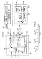
- FIG. 5 illustrates the use of BIS referenced 403 in the example embodiment of FIG. 4, when the processing unit 214 receives a signal 51 and simultaneously transmits an internal signal 52 to the unit of 213.
- the signal referenced 51 corresponds to the preprocessed signal derived from a satellite external signal and the signal referenced 52 corresponds to the internal signal.
- These two signals occupy separate frequency sub-bands included in the previously defined BIS As a result, they can be transmitted simultaneously.
- the command signal issued by the unit 213 and referenced 53 is shown outside the BIS but in a band of adjacent frequency preferably between 900 and 950 MHz.
- Figure 6 illustrates part of a receiving facility satellite comprising two processing units 213 and 214, in which the port 211 of the distribution entity 207 allows the processing unit 214 to receive an external signal, derived from a satellite signal, for a reading immediately (for display on a television screen connected to this unit by example, to record another external signal in the memory, and to transmit to the processing unit 213 at a frequency included in the BIS an internal signal from data retrieved from the memory.
- the signal read and the recorded signal that can be derived from two separate pretreated signals from an initial satellite signal.
- the evolved port 211 of the entity of distribution 207 is here correlated to two outputs of the matrix and therefore to two pretreated signals that may be different, each of these two signals being shifted then filtered by the 401 shift and filtering function before being transmitted over a single coaxial cable 217.
- FIG 7 illustrates the use of the BIS referenced 403 cable coaxial in the example given above.
- the signal referenced 71 (or P for Play in English) is the external signal for immediate playback
- the signal referenced 72 (or R for Record in English) corresponds to the signal registered external
- the signal referenced 52 corresponds to the internal signal transmitted by the processing unit 214 to the processing unit 213.
- These signals are frequency-divided within the previously defined BIS.
- the signals 71 and 72 from an external initial signal are transmitted in a first sub frequency band and the internal signal 52 is transmitted in a second sub frequency band, the two sub frequency bands being distinct.
- the control signal 53 is also represented as in Figure 5.
- a receiving installation satellite with a larger number of processing units and with a signal distribution entity having a number of ports corresponding to the number of treatment units.
- a distribution entity according to one embodiment of the invention including multiple advanced ports is also possible.
- the ports of such a distribution entity of signal further include an offset and filter function 401.
- Figure 8 illustrates part of a receiving facility satellite according to one embodiment of the invention in which the means connection 209 differ from the previously described embodiments.
- all the outputs of the switching matrix 208 are provided with a offset function and filtering 401. Therefore, all signals pretreated and switched are shifted and filtered to be transmitted in the first sub frequency band.
- the processing unit 214 upon receipt of a data request signal, returns data read in the memory 303 and re-module these data under form of an RF signal to transmit data via coaxial cable 217 in the second subband of determined frequency.
- the distribution entity signal 207 includes an impedance which causes the reflection of the signal received from the processing entity 214 and re-modulated in the second subband determined frequency.
- the signal transmitted by the unit of processing 214 is reflected by the signal distribution entity 207 and by therefore it is retransmitted on all the coaxial cables out of the entity of signal distribution via a power divider referenced 802.
- a internal connection is thus established from the processing unit 214 to the unit of treatment 213 by reflection of the signal on a cable of an impedance determined.
- the value of the impedance is chosen to offer a coefficient of non-zero reflection for the second sub-frequency band determined for the re-modulation of the signal emitted by the unit 214.
- the command signal previously sent by unit 213 to unit 214 could be transmitted as has been described in the example of FIG. microcontroller.
- the value the impedance is chosen to offer a coefficient of reflection also no zero for a third subband of determined frequency included in the BIS.
- the control signal is re-modulated by the re-modulator 404 of unit 213 in the third sub frequency band before being transmitted over the cable 216.
- FIG. 9 illustrates the use of BIS in such an installation.
- the four external signals B1, B2, B3 and B4, derived from a satellite signal, are transmitted in the first sub frequency band simultaneously with the transmission of the internal signal 52 from the processing unit 214 to the processing unit 213.
- the internal signal 52 is emitted by the processing unit 214 in the second sub frequency band.
- the coaxial cable connected to the port 801 can simultaneously transmit external signals B1, B2, B3, B4 and the internal signal 52.
- the plant's processing unit satellite reception system 214 also functions in a manner equivalent to a digital video recorder.
- the data transmitted by unit 214 to unit 213 are described as being read from memory 303. heard, the data included in the signal transmitted by unit 214 to the unit 213 may come from sources other than the memory 303, as example of a network external to the satellite reception facility.
- the unit 214 may be provided with a connection module to one or more external networks, such as the telephone network, and as a result the data included in the internal signal sent by unit 214 to the unit 213 may come from the external network or networks.
- units of the same installation can be connected to the external network via the processing unit referenced here 214.
- Another interesting application of a embodiment of the invention is to share a management function of decoding rights.
- unit 214 may include a function to adapt to manage and store the corresponding encryption keys for example to each unit of the installation. Thus, as soon as a processing unit is set powered on, it requires information about its decoding rights from unit 214 which stores this information.
- a unit of processing can advantageously include functions to be shared and operate as a master processing unit while the other one or Processing units operate as a slave processing unit.
- the present invention advantageously proposes an entity of signal distribution within a satellite reception facility according to a embodiment of the invention that can be manufactured very easily and at a low cost of production.
- another advantage of the invention is the the ease with which it is possible to install an entity according to a embodiment of the invention.
- an entity may be integrated in the receiver (or LNB) and therefore just change the LNB, as is already done when a user wishes to add, for example, processing units within his facility.
- Such an entity may also be integrated in a box connected to a receiver and the replacement of a such housing is also easy to do. Therefore, the previous installation and the existing wiring, whether coaxial cable or other types of wire link, can remain unchanged thanks to the implementation of the present invention.
- a significant advantage of an embodiment of the invention is that it can be implemented at low cost by using existing components in such installations.
Landscapes
- Engineering & Computer Science (AREA)
- Signal Processing (AREA)
- Physics & Mathematics (AREA)
- Astronomy & Astrophysics (AREA)
- General Physics & Mathematics (AREA)
- Multimedia (AREA)
- Input Circuits Of Receivers And Coupling Of Receivers And Audio Equipment (AREA)
- Radio Relay Systems (AREA)
- Details Of Television Systems (AREA)
- Two-Way Televisions, Distribution Of Moving Picture Or The Like (AREA)
Applications Claiming Priority (2)
| Application Number | Priority Date | Filing Date | Title |
|---|---|---|---|
| FR0400502 | 2004-01-20 | ||
| FR0400502 | 2004-01-20 |
Publications (2)
| Publication Number | Publication Date |
|---|---|
| EP1558035A1 true EP1558035A1 (de) | 2005-07-27 |
| EP1558035B1 EP1558035B1 (de) | 2008-06-11 |
Family
ID=34630649
Family Applications (1)
| Application Number | Title | Priority Date | Filing Date |
|---|---|---|---|
| EP05290076A Expired - Lifetime EP1558035B1 (de) | 2004-01-20 | 2005-01-12 | Übertragungssystem und -verfahren in Satelliten-Hausverteilungsanlagen |
Country Status (4)
| Country | Link |
|---|---|
| US (1) | US7577401B2 (de) |
| EP (1) | EP1558035B1 (de) |
| JP (1) | JP2005210724A (de) |
| DE (1) | DE602005007392D1 (de) |
Cited By (1)
| Publication number | Priority date | Publication date | Assignee | Title |
|---|---|---|---|---|
| EP1713272A1 (de) * | 2005-04-12 | 2006-10-18 | THOMSON Licensing | Vorrichtung und Verfahren zur Paarung eines Master-Dekodierers mit Slave-Dekodierern und Empfangssystem mit dieser Vorrichtung |
Families Citing this family (2)
| Publication number | Priority date | Publication date | Assignee | Title |
|---|---|---|---|---|
| JP4852529B2 (ja) * | 2004-03-09 | 2012-01-11 | トムソン ライセンシング | セットトップボックス装置及びその方法 |
| US8903306B2 (en) * | 2008-09-26 | 2014-12-02 | Thomson Licensing | Method for controlling signal transmission for multiple devices |
Citations (9)
| Publication number | Priority date | Publication date | Assignee | Title |
|---|---|---|---|---|
| US5760822A (en) * | 1996-01-30 | 1998-06-02 | Lucent Technologies Inc. | Central node converter for local network having single coaxial cable |
| DE19749120A1 (de) * | 1997-11-06 | 1999-06-02 | Kathrein Werke Kg | Satelliten-Empfangsanlage sowie zugehöriger Datenbus |
| JP2000232462A (ja) * | 1999-02-10 | 2000-08-22 | Showa Electric Wire & Cable Co Ltd | ホームネットワークシステム |
| WO2001017143A1 (en) * | 1999-08-27 | 2001-03-08 | Koninklijke Philips Electronics N.V. | In-home network using an existing coaxial cable installation |
| DE20008239U1 (de) * | 2000-05-10 | 2001-06-13 | Resch Electronic Innovation Gm | Multischalter für Satelliten-Zwischenfrequenz-Verteilung |
| WO2002065780A1 (en) * | 2001-02-14 | 2002-08-22 | Satellite Accessories, Llc | Broadcast television and satellite signal switching system and method for telephony signal insertion |
| DE10155481A1 (de) * | 2001-11-13 | 2003-05-28 | Fachhochschule Dortmund | Einrichtung zur Steuerung und Überwachung der Freigabe von Empfangssignalen an Anschlussstellen innerhalb von kabelgebundenen Hausverteilungsanlagen |
| FR2835368A1 (fr) * | 2002-01-29 | 2003-08-01 | St Microelectronics Sa | Transmission de signaux sur un cable coaxial |
| WO2004038965A1 (fr) * | 2002-10-23 | 2004-05-06 | Thomson Licensing Sa | Dispositif de distribution de signaux radio et systeme de reception incorporant ledit dispositif |
Family Cites Families (8)
| Publication number | Priority date | Publication date | Assignee | Title |
|---|---|---|---|---|
| JPH09102917A (ja) * | 1995-10-04 | 1997-04-15 | Pioneer Electron Corp | 信号再生装置 |
| TW322632B (en) * | 1996-10-14 | 1997-12-11 | Vanguard Int Semiconduct Corp | Electrostatic discharge protection device for integrated circuit input/output port |
| KR20010034333A (ko) * | 1998-01-23 | 2001-04-25 | 와다 아끼히로 | 과금처리장치, 과금처리시스템, 및 과금처리용 카드 |
| US6826647B1 (en) * | 2000-05-02 | 2004-11-30 | Communications-Applied Technology Co., Inc. | Voice operated communications interface |
| JP2002354450A (ja) * | 2001-05-28 | 2002-12-06 | Matsushita Electric Ind Co Ltd | Stb遠隔操作システム |
| JP2003051833A (ja) * | 2001-08-06 | 2003-02-21 | Synclayer Inc | 屋内通信システム及び中継装置 |
| US7130576B1 (en) * | 2001-11-07 | 2006-10-31 | Entropic Communications, Inc. | Signal selector and combiner for broadband content distribution |
| JP3888239B2 (ja) * | 2002-06-20 | 2007-02-28 | 日本ビクター株式会社 | デジタル音声処理方法及び装置、並びにコンピュータプログラム |
-
2005
- 2005-01-12 EP EP05290076A patent/EP1558035B1/de not_active Expired - Lifetime
- 2005-01-12 DE DE602005007392T patent/DE602005007392D1/de not_active Expired - Fee Related
- 2005-01-19 US US11/040,169 patent/US7577401B2/en not_active Expired - Fee Related
- 2005-01-19 JP JP2005011616A patent/JP2005210724A/ja active Pending
Patent Citations (9)
| Publication number | Priority date | Publication date | Assignee | Title |
|---|---|---|---|---|
| US5760822A (en) * | 1996-01-30 | 1998-06-02 | Lucent Technologies Inc. | Central node converter for local network having single coaxial cable |
| DE19749120A1 (de) * | 1997-11-06 | 1999-06-02 | Kathrein Werke Kg | Satelliten-Empfangsanlage sowie zugehöriger Datenbus |
| JP2000232462A (ja) * | 1999-02-10 | 2000-08-22 | Showa Electric Wire & Cable Co Ltd | ホームネットワークシステム |
| WO2001017143A1 (en) * | 1999-08-27 | 2001-03-08 | Koninklijke Philips Electronics N.V. | In-home network using an existing coaxial cable installation |
| DE20008239U1 (de) * | 2000-05-10 | 2001-06-13 | Resch Electronic Innovation Gm | Multischalter für Satelliten-Zwischenfrequenz-Verteilung |
| WO2002065780A1 (en) * | 2001-02-14 | 2002-08-22 | Satellite Accessories, Llc | Broadcast television and satellite signal switching system and method for telephony signal insertion |
| DE10155481A1 (de) * | 2001-11-13 | 2003-05-28 | Fachhochschule Dortmund | Einrichtung zur Steuerung und Überwachung der Freigabe von Empfangssignalen an Anschlussstellen innerhalb von kabelgebundenen Hausverteilungsanlagen |
| FR2835368A1 (fr) * | 2002-01-29 | 2003-08-01 | St Microelectronics Sa | Transmission de signaux sur un cable coaxial |
| WO2004038965A1 (fr) * | 2002-10-23 | 2004-05-06 | Thomson Licensing Sa | Dispositif de distribution de signaux radio et systeme de reception incorporant ledit dispositif |
Non-Patent Citations (2)
| Title |
|---|
| EUROPEAN TELECOMMUNICATIONS SATELLITE ORGANIZATION: "Technical Recommandations for Manufacturers of DTH and SMATV Receiving Equipment - DiSEqC Version 4.0 - BUS FUNCTIONAL SPECIFICATION", ETSO, 22 March 1996 (1996-03-22), XP002149629 * |
| PATENT ABSTRACTS OF JAPAN vol. 2000, no. 11 3 January 2001 (2001-01-03) * |
Cited By (2)
| Publication number | Priority date | Publication date | Assignee | Title |
|---|---|---|---|---|
| EP1713272A1 (de) * | 2005-04-12 | 2006-10-18 | THOMSON Licensing | Vorrichtung und Verfahren zur Paarung eines Master-Dekodierers mit Slave-Dekodierern und Empfangssystem mit dieser Vorrichtung |
| US7814527B2 (en) | 2005-04-12 | 2010-10-12 | Thomson Licensing | Device and process for pairing a master decoder and slave decoders and reception system incorporating said device |
Also Published As
| Publication number | Publication date |
|---|---|
| US7577401B2 (en) | 2009-08-18 |
| DE602005007392D1 (de) | 2008-07-24 |
| US20050227613A1 (en) | 2005-10-13 |
| JP2005210724A (ja) | 2005-08-04 |
| EP1558035B1 (de) | 2008-06-11 |
Similar Documents
| Publication | Publication Date | Title |
|---|---|---|
| US9860591B2 (en) | Passive multi-port entry adapter and method for preserving downstream CATV signal strength within in-home network | |
| CA2192610C (en) | Central node converter for local network having single coaxial cable | |
| US20210344870A1 (en) | Method and apparatus for reducing isolation in a home network | |
| FR2665319A1 (fr) | Dispositif de distribution de signaux video et/ou audio entre plusieurs recepteurs. | |
| US20180160170A1 (en) | Passive multi-port entry adapter and method for preserving downstream catv signal strength within in-home network | |
| FR2737365A1 (fr) | Procede et dispositif de transmission de service multimedia sur reseau prive large bande | |
| EP1331749B1 (de) | Mehrfachsignalübertragung über ein Koaxialkabel | |
| FR2854015A1 (fr) | Convertisseur et procede de conversion de signaux numeriques recus sous forme modulee et multiplexee | |
| EP1558035B1 (de) | Übertragungssystem und -verfahren in Satelliten-Hausverteilungsanlagen | |
| FR2844950A1 (fr) | Dispositif et procede de routage destines au transport de donnees video numeriques demodulees, et recepteur de television numerique mettant en oeuvre ce routage | |
| EP3900219B1 (de) | Verfahren um eine mobilfunkverbinbung in einem geschlossenen raum durch eine externe fernsehantenne bereitzustellen und entsprechende vorrichtung | |
| WO2004038965A1 (fr) | Dispositif de distribution de signaux radio et systeme de reception incorporant ledit dispositif | |
| WO2006013274A1 (fr) | Reseau privatif multiservices et modules d'interface permettant de vehiculer, sur un tel reseau, des donnees sous differents formats | |
| FR2871327A1 (fr) | Distribution audiovisuelle locale | |
| FR2879390A1 (fr) | Terminal micro-onde multibandes | |
| BE1023989B1 (fr) | Ensemble pour caméra avec système de ralenti | |
| FR2948526A1 (fr) | Systeme pour le traitement de ressources interactives televisuelles. | |
| EP1804500A1 (de) | Selbständiger Mehrzweck-Fernsehgerät | |
| FR2947133A1 (fr) | Procede de controle d'un decodeur et decodeur mettant en ouvre un tel procede. | |
| FR2940870A1 (fr) | Systeme de distribution de flux multimedia | |
| FR2973633A1 (fr) | Restitution en differe de donnees. | |
| EP2200317A1 (de) | Quellvorrichtung eines audiovisuellen Kommunikationsnetzes im Haus, Verwaltungsverfahren und entsprechendes Computerprogramm-Produkt. | |
| FR2927757A1 (fr) | Systeme de videosurveillance embarquee nomade. | |
| FR2956550A1 (fr) | Systeme et procede d'acces a des sources numeriques a partir de postes de television. | |
| FR2973182A1 (fr) | Procede de multiplexage de canaux adjacents d'un reseau de diffusion de television numerique terrestre et dispositif emetteur-recepteur mettant en oeuvre un tel procede |
Legal Events
| Date | Code | Title | Description |
|---|---|---|---|
| PUAI | Public reference made under article 153(3) epc to a published international application that has entered the european phase |
Free format text: ORIGINAL CODE: 0009012 |
|
| AK | Designated contracting states |
Kind code of ref document: A1 Designated state(s): AT BE BG CH CY CZ DE DK EE ES FI FR GB GR HU IE IS IT LI LT LU MC NL PL PT RO SE SI SK TR |
|
| AX | Request for extension of the european patent |
Extension state: AL BA HR LV MK YU |
|
| 17P | Request for examination filed |
Effective date: 20060126 |
|
| AKX | Designation fees paid |
Designated state(s): DE FR GB IT |
|
| GRAP | Despatch of communication of intention to grant a patent |
Free format text: ORIGINAL CODE: EPIDOSNIGR1 |
|
| GRAS | Grant fee paid |
Free format text: ORIGINAL CODE: EPIDOSNIGR3 |
|
| GRAA | (expected) grant |
Free format text: ORIGINAL CODE: 0009210 |
|
| AK | Designated contracting states |
Kind code of ref document: B1 Designated state(s): DE FR GB IT |
|
| REG | Reference to a national code |
Ref country code: GB Ref legal event code: FG4D Free format text: NOT ENGLISH |
|
| REF | Corresponds to: |
Ref document number: 602005007392 Country of ref document: DE Date of ref document: 20080724 Kind code of ref document: P |
|
| PLBE | No opposition filed within time limit |
Free format text: ORIGINAL CODE: 0009261 |
|
| STAA | Information on the status of an ep patent application or granted ep patent |
Free format text: STATUS: NO OPPOSITION FILED WITHIN TIME LIMIT |
|
| 26N | No opposition filed |
Effective date: 20090312 |
|
| PG25 | Lapsed in a contracting state [announced via postgrant information from national office to epo] |
Ref country code: IT Free format text: LAPSE BECAUSE OF FAILURE TO SUBMIT A TRANSLATION OF THE DESCRIPTION OR TO PAY THE FEE WITHIN THE PRESCRIBED TIME-LIMIT Effective date: 20080611 |
|
| GBPC | Gb: european patent ceased through non-payment of renewal fee |
Effective date: 20090112 |
|
| PG25 | Lapsed in a contracting state [announced via postgrant information from national office to epo] |
Ref country code: DE Free format text: LAPSE BECAUSE OF NON-PAYMENT OF DUE FEES Effective date: 20090801 |
|
| REG | Reference to a national code |
Ref country code: FR Ref legal event code: ST Effective date: 20091030 |
|
| PG25 | Lapsed in a contracting state [announced via postgrant information from national office to epo] |
Ref country code: GB Free format text: LAPSE BECAUSE OF NON-PAYMENT OF DUE FEES Effective date: 20090112 |
|
| PG25 | Lapsed in a contracting state [announced via postgrant information from national office to epo] |
Ref country code: FR Free format text: LAPSE BECAUSE OF NON-PAYMENT OF DUE FEES Effective date: 20090202 |