EP1558467B1 - Gestell für warndreiecke - Google Patents
Gestell für warndreiecke Download PDFInfo
- Publication number
- EP1558467B1 EP1558467B1 EP03773662A EP03773662A EP1558467B1 EP 1558467 B1 EP1558467 B1 EP 1558467B1 EP 03773662 A EP03773662 A EP 03773662A EP 03773662 A EP03773662 A EP 03773662A EP 1558467 B1 EP1558467 B1 EP 1558467B1
- Authority
- EP
- European Patent Office
- Prior art keywords
- opening
- bearing
- diameter
- pin
- frame according
- Prior art date
- Legal status (The legal status is an assumption and is not a legal conclusion. Google has not performed a legal analysis and makes no representation as to the accuracy of the status listed.)
- Expired - Lifetime
Links
- 239000007787 solid Substances 0.000 abstract description 2
- 230000001419 dependent effect Effects 0.000 description 1
- 239000000463 material Substances 0.000 description 1
- 239000002184 metal Substances 0.000 description 1
Images



Classifications
-
- B—PERFORMING OPERATIONS; TRANSPORTING
- B60—VEHICLES IN GENERAL
- B60Q—ARRANGEMENT OF SIGNALLING OR LIGHTING DEVICES, THE MOUNTING OR SUPPORTING THEREOF OR CIRCUITS THEREFOR, FOR VEHICLES IN GENERAL
- B60Q7/00—Arrangement or adaptation of portable emergency signal devices on vehicles
-
- G—PHYSICS
- G09—EDUCATION; CRYPTOGRAPHY; DISPLAY; ADVERTISING; SEALS
- G09F—DISPLAYING; ADVERTISING; SIGNS; LABELS OR NAME-PLATES; SEALS
- G09F13/00—Illuminated signs; Luminous advertising
- G09F13/16—Signs formed of or incorporating reflecting elements or surfaces, e.g. warning signs having triangular or other geometrical shape
Definitions
- the invention relates to a frame according to the preamble of claim 1.
- the legs are hingedly connected to the base body via a respective bearing section, wherein the ends of the legs are inserted into openings provided for this purpose. This gives the legs an undesirable game.
- the end portions of the base body are solid designed to achieve the required stability.
- the present invention seeks to further develop the generic frame without undue constructive effort so that the assembly of the frame with less material, higher speed and safe storage of the individual parts can be done.
- the invention is in any case realized if it is a frame whose base body has at its two end sides bearing openings, in which the two legs are articulated by connectors anorderbar.
- one leg has an opening
- the second leg carries a pin, which first passes through the bearing opening of the end part and is then inserted through the opening of the second leg.
- the pin is dimensioned so that it passes through both openings and protrudes from the opening of the bearing body, but holds together the three parts articulated and operational.
- a particularly advantageous embodiment provides that the bearing body and the pin are separate parts that are operatively connected to the legs.
- the regular legs made of metal or plastic can be formed as rods, which are then connected to the bearing body or pin through connectors.
- a further embodiment provides that the pin is part of a plug-in body, which is articulated with both legs and with the bearing body and the base body.
- the plug body and the bearing body have stop parts, with the stop bodies of the Base body work together.
- the stopper body define the rest position and the operating position of the legs. Through these measures can be achieved that the legs can always assume a defined work or rest position.
- a further advantageous embodiment provides that the pin has a neck portion with an opening and an elastically deformable head portion whose diameter is greater in the relaxed state than the diameter of the opening and which are supported on the free side of the bearing body.
- a folded warning triangle for motor vehicles which has three retroreflective strips, each of which a bar is pivotally connected to the ends of the third base bar.
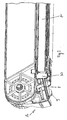
- the frame 10 for warning triangles has a horizontally oriented base body 12, on the legs 14 are hinged end legs and has in the region of its end parts 16, 18 bearing openings 20 for the legs 14.
- the one leg is hinged to the base body 12 via a layer body 40, 42, while the second leg 14 carries a bearing opening 20 of the base body 12 and the opening 42 of the bearing body 40 passing through pin 32.
- the bearing body 40 and the pin 32 are separate parts which are operatively connected to the legs 14.
- the pin 32 is part of a plug-in body 30 which is connectable by plugging both with the leg 14 and with the bearing body 40 and the base body 12.
- the plug body 30 and the bearing body 40 stop parts 35, 36; 43, 44 which cooperate with stop bodies 8, 9 of the base body 12.
- the task of the stopper body 8, 9 is to define the rest position and the operating position of the legs 14 when swinging out or the legs 14.
- Fig. 4 can be seen that the pin 32nd a neck portion 36 having an opening 33 and an elastically deformable head portion 34, whose diameter in the relaxed state is greater than the diameter of the opening 42.
- the head portion 34 is supported on the free side 45 of the bearing body 40 from.
- the diameter of the cylindrical neck portion 36 corresponds to the diameter of the bearing opening 20 and the diameter of the opening 42.
- Fig. 2 can be seen in connection with Fig. 4 that the leg 14 is held in the folded state of projections 39 which are elastically deformable.
- the pillar 30 supported by the leg is inserted in the recess 37.
- the projection 38 of FIG. 4 serves as a stop of the plug body 30 to the base body 12th
Landscapes
- Physics & Mathematics (AREA)
- Engineering & Computer Science (AREA)
- Geometry (AREA)
- General Physics & Mathematics (AREA)
- Theoretical Computer Science (AREA)
- Mechanical Engineering (AREA)
- Pivots And Pivotal Connections (AREA)
- Materials For Medical Uses (AREA)
- Professional, Industrial, Or Sporting Protective Garments (AREA)
- Dental Preparations (AREA)
- Road Signs Or Road Markings (AREA)
- Insertion Pins And Rivets (AREA)
- Special Wing (AREA)
- Sub-Exchange Stations And Push- Button Telephones (AREA)
- Toys (AREA)
Description
- Die Erfindung betrifft ein Gestell nach dem Oberbegriff des Anspruches 1.
- Bei herkömmlichen Gestellen der eingangs genannten Art, wie sie z.B. in der EP 864 464 offenbart sind, sind die Standbeine mit dem Basiskörper über jeweils eine Lagerpartie gelenkig verbunden, wobei die Enden der Standbeine in dafür vorgesehene Öffnungen gesteckt sind. Hierdurch bekommen die Standbeine ein unerwünschtes Spiel. Zudem sind die Endpartien des Basiskörpers massiv ausgebildet, um die erforderliche Stabilität zu erreichen.
- Ausgehend von dem obigen Stand der Technik liegt der Erfindung die Aufgabe zugrunde, das gattungsgemäße Gestell ohne unangemessenen konstruktiven Aufwand so weiterzubilden, dass der Zusammenbau des Gestells mit weniger Materialaufwand, höherer Geschwindigkeit und sicherer Lagerung der einzelnen Teile erfolgen kann.
- Die gestellte Aufgabe wird erfindungsgemäß durch die Merkmale des Anspruches 1 gelöst.
- Man erkennt, dass die Erfindung jedenfalls dann verwirklicht ist, wenn es sich um ein Gestell handelt, dessen Basiskörper an seinen beiden Endseiten Lageröffnungen aufweist, in welche die beiden Standbeine durch Steckverbindungen gelenkig anorderbar sind. Dabei weist das eine Standbein eine Öffnung auf, während das zweite Standbein einen Zapfen trägt, der zunächst die Lageröffnung der Endpartie durchquert und anschließend durch die Öffnung des zweiten Standbeines gesteckt wird. Der Zapfen ist dabei so bemessen, dass er beide Öffnungen durchquert und aus der Öffnung des Lagerkörpers herausragt, jedoch die drei Teile gelenkig und betriebsgemäß zusammenhält.
- Weitere zweckmäßige und vorteilhafte Ausgestaltungen der Erfindung gehen aus den Unteransprüchen der Erfindung hervor.
- Eine besonders zweckmäßige Ausgestaltung sieht vor, dass der Lagerkörper sowie der Zapfen separate Teile sind, die mit den Standbeinen betriebsgemäß verbindbar sind. Auf diese Weise können die regelmäßig aus Metall oder Kunststoff bestehenden Standbeine als Stäbe ausgebildet werden, die danach mit dem Lagerkörper bzw. Zapfen durch Steckverbindungen verbindbar sind.
- Eine weitere Ausgestaltung sieht vor, dass der Zapfen Teil eines Steckkörpers ist, der sowohl mit denn Standbeinen als auch mit dem Lagerkörper sowie dem Basiskörper gelenkig verbindbar ist.
- Eine weitere zweckmäßige Ausgestaltung sieht vor, dass der Steckkörper und der Lagerkörper Anschlagpartien besitzen, die mit den Anschlagkörpern des Basiskörpers zusammenarbeiten. Im Rahmen dieses Erfindungsgedankens ist es zweckmäßig, wenn die Anschlagkörper die Ruhestellung sowie die Betriebsstellung der Standbeine definieren. Durch diese Maßnahmen ist erreichbar, dass die Standbeine immer eine definierte Arbeits- bzw. Ruhestellung einnehmen können.
- Eine weitere zweckmäßige Ausgestaltung sieht vor, dass der Zapfen eine Halspartie mit einer Öffnung sowie einer elastisch verformbaren Kopfpartie aufweist, deren Durchmesser im entspannten Zustand größer ist als der Durchmesser der Öffnung und die sich auf der freien Seite des Lagerkörpers abstützen. Durch diese Maßnahmen wird eine flexible Steckverbindung zwischen den einzelnen Teilen hergestellt, die ohne weiteres gelöst werden kann. Durch diese Maßnahme wird nicht nur die Herstellung der Beine, sondern auch der eigentlichen Steckverbindung deutlich vereinfacht.
- Ein Ausführungsbeispiel der Erfindung ist in der Zeichnung schematisch dargestellt und ist im Folgenden erläutert. Es zeigen:
- Fig. 1
- ein Warndreieck im zusammengeklappten Zustand,
- Fig. 2
- den mit II bezeichneten Teil nach Fig. 1 vergrößert dargestellt,
- Fig. 3
- den Teil nach Fig. 2, jedoch ohne Standbeine,
- Fig. 4
- einen Steckkörper in perspektivischer Ansicht,
- Fig. 5
- den Steckkörper nach Fig. 4 in einer anderen perspektivischen Ansicht,
- Fig. 6
- einen Lagerkörper in Seitenansicht,
- Fig. 7
- den Lagerkörper nach Fig. 6 in Richtung des Pfeiles VII.
- In den Fig. 1 bis 3 ist ein zusammengeklapptes Warndreieck für Kraftfahrzeuge dargestellt, das drei rückstrahlende Leisten aufweist, von denen je eine Leiste mit den Enden der dritten Basisleiste schwenkbar verbunden ist.
- Das Gestell 10 für Warndreiecke weist einen waagerecht ausgerichteten Basiskörper 12 auf, an dem endseitig Standbeine 14 angelenkt sind und der im Bereich seiner Endpartien 16, 18 Lageröffnungen 20 für die Standbeine 14 aufweist. Das eine Standbein ist an dem Basiskörper 12 über einen Lagekörper 40, 42 angelenkt, während das zweite Standbein 14 einen die Lageröffnung 20 des Basiskörpers 12 sowie die Öffnung 42 des Lagerkörpers 40 durchquerenden Zapfen 32 trägt.
- Der Lagerkörper 40 sowie der Zapfen 32 sind separate Teile, die mit den Standbeinen 14 betriebsgemäß verbindbar sind. Der Zapfen 32 ist Teil eines Steckkörpers 30, der sowohl mit dem Standbein 14 als auch mit dem Lagerkörper 40 sowie dem Basiskörper 12 durch Stecken verbindbar ist.
- Man erkennt, dass der Steckkörper 30 und der Lagerkörper 40 Anschlagpartien 35, 36; 43, 44 besitzen, die mit Anschlagkörpern 8, 9 des Basiskörpers 12 zusammenarbeiten. Die Aufgabe der Anschlagkörper 8, 9 ist, die Ruhestellung sowie die Betriebsstellung der Standbeine 14 beim Aus- oder Einschwenken der Standbeine 14 zu definieren. Ferner lässt Fig. 4 erkennen, dass der Zapfen 32 eine Halspartie 36 mit einer Öffnung 33 sowie eine elastisch verformbare Kopfpartie 34 aufweist, deren Durchmesser im entspannten Zustand größer ist als der Durchmesser der Öffnung 42. Die Kopfpartie 34 stützt sich auf der freien Seite 45 des Lagerkörpers 40 ab. Der Durchmesser der zylindrischen Halspartie 36 entspricht dem Durchmesser der Lageröffnung 20 und dem Durchmesser der Öffnung 42.
- Die Fig. 2 lässt im Zusammenhang mit Fig. 4 erkennen, dass das Standbein 14 im eingeklappten Zustand von Vorsprüngen 39 festgehalten wird, die elastisch verformbar sind. Das von dem Steckkörper 30 getragene Standbein ist in der Ausnehmung 37 eingesteckt. Der Vorsprung 38 nach Fig. 4 dient als Anschlag des Steckkörpers 30 an Basiskörper 12.
Claims (7)
- Gestell (10) für Warndreiecke mit einem waagerecht ausgerichteten Basiskörper (12), an dem endseitig Standbeine (14) angelenkt sind und der im Bereich seiner Endpartien (16, 18) Lageröffnungen (20) für die Standbeine (14) aufweist,
dadurch gekennzeichnet,
dass das eine Standbein an den Basiskörper (12) über einen Lagerkörper (40) mit Öffnung (42) angelenkt ist, während das zweite Standbein (14) einen die Lageröffnung (20) des Basiskörpers (12) sowie die Öffnung (42) des Lagerkörpers (40) durchquerenden Zapfen (32) trägt. - Gestell nach Anspruch 1,
dadurch gekennzeichnet,
dass der Lagerkörper (40) sowie der Zapfen (32) separate Teile sind, die mit den Standbeinen (14) betriebsgemäß verbindbar sind. - Gestell nach Anspruch 1 oder 2,
dadurch gekennzeichnet,
dass der Zapfen (32) Teil eines Steckkörpers (30) ist, der sowohl mit dem Standbein (14) als auch mit dem Lagerkörper (40) sowie dem Basiskörper (12) gelenkig verbindbar ist. - Gestell nach einem der Ansprüche 1 bis 3,
dadurch gekennzeichnet,
dass der Steckkörper (30) und der Lagerkörper (40) Anschlagpartien (35, 36; 43, 44) besitzen, die mit Anschlagkörpern (8, 9) des Basiskörpers (12) zusammenarbeiten. - Gestell nach einem der Ansprüche 1 bis 4,
dadurch gekennzeichnet,
dass die Anschlagkörper (8, 9) die Ruhestellung sowie die Betriebsstellung der verschwenkbaren Standbeine (14) definieren. - Gestell nach einem der Ansprüche 1 bis 5,
dadurch gekennzeichnet,
dass der Zapfen (32) eine Halspartie (36) mit einer Öffnung (33) sowie eine elastisch verformbare Kopfpartie (34) aufweist, deren Durchmesser im entspannten Zustand größer ist als der Durchmesser der Öffnung (42), und die sich auf der freien Seite (45) des Lagerkörpers abstützt. - Gestell nach einem der Ansprüche 1 bis 6,
dadurch gekennzeichnet,
dass der Durchmesser der zylindrischen Halspartie (36) dem Durchmesser der Lageröffnung (20) und dem Durchmesser der Öffnung (42) entspricht.
Applications Claiming Priority (3)
| Application Number | Priority Date | Filing Date | Title |
|---|---|---|---|
| DE10250042A DE10250042A1 (de) | 2002-10-25 | 2002-10-25 | Gestell für Warndreiecke |
| DE10250042 | 2002-10-25 | ||
| PCT/EP2003/011837 WO2004037609A1 (de) | 2002-10-25 | 2003-10-24 | Gestell für warndreiecke |
Publications (2)
| Publication Number | Publication Date |
|---|---|
| EP1558467A1 EP1558467A1 (de) | 2005-08-03 |
| EP1558467B1 true EP1558467B1 (de) | 2006-05-10 |
Family
ID=32087231
Family Applications (1)
| Application Number | Title | Priority Date | Filing Date |
|---|---|---|---|
| EP03773662A Expired - Lifetime EP1558467B1 (de) | 2002-10-25 | 2003-10-24 | Gestell für warndreiecke |
Country Status (8)
| Country | Link |
|---|---|
| EP (1) | EP1558467B1 (de) |
| CN (1) | CN1708424A (de) |
| AT (1) | ATE325725T1 (de) |
| AU (1) | AU2003282047A1 (de) |
| DE (2) | DE10250042A1 (de) |
| ES (1) | ES2265591T3 (de) |
| WO (1) | WO2004037609A1 (de) |
| ZA (1) | ZA200503274B (de) |
Families Citing this family (1)
| Publication number | Priority date | Publication date | Assignee | Title |
|---|---|---|---|---|
| ITMI20072295A1 (it) * | 2007-12-06 | 2009-06-07 | Autotek Srl | Dispositivo di segnalazione di sosta di emergenza per autoveicoli in genere, in particolare triangolo di segnalazione. |
Family Cites Families (6)
| Publication number | Priority date | Publication date | Assignee | Title |
|---|---|---|---|---|
| DE19628746A1 (de) * | 1996-07-17 | 1998-01-22 | Geka Guenther & Kastl Gmbh | Warndreieck |
| DE19710074A1 (de) * | 1997-03-12 | 1998-09-17 | Raderschad Gebra Plastik | Zusamenlegbares Warndreieck |
| DE29902459U1 (de) * | 1999-02-12 | 2000-06-29 | Leina-Werk GmbH, 51570 Windeck | Zusammenlegbares Warndreieck |
| DE10008067C1 (de) * | 2000-02-22 | 2001-08-02 | Raderschad Gebra Plastik | Zusammenlegbares Warndreieck |
| DE20007407U1 (de) * | 2000-03-01 | 2000-08-17 | Ing. Gerhard Dekorsy GmbH, 78315 Radolfzell | Zusammenklappbares Warndreieck |
| DE10054656C2 (de) * | 2000-11-03 | 2003-03-06 | Gebra Gmbh & Co Sicherheitspro | Zusammenklappbares Warndreieck |
-
2002
- 2002-10-25 DE DE10250042A patent/DE10250042A1/de not_active Withdrawn
-
2003
- 2003-10-24 WO PCT/EP2003/011837 patent/WO2004037609A1/de not_active Ceased
- 2003-10-24 DE DE50303315T patent/DE50303315D1/de not_active Expired - Fee Related
- 2003-10-24 CN CN200380102083.5A patent/CN1708424A/zh active Pending
- 2003-10-24 ES ES03773662T patent/ES2265591T3/es not_active Expired - Lifetime
- 2003-10-24 AU AU2003282047A patent/AU2003282047A1/en not_active Abandoned
- 2003-10-24 AT AT03773662T patent/ATE325725T1/de not_active IP Right Cessation
- 2003-10-24 EP EP03773662A patent/EP1558467B1/de not_active Expired - Lifetime
-
2005
- 2005-04-22 ZA ZA200503274A patent/ZA200503274B/en unknown
Also Published As
| Publication number | Publication date |
|---|---|
| ES2265591T3 (es) | 2007-02-16 |
| DE50303315D1 (de) | 2006-06-14 |
| CN1708424A (zh) | 2005-12-14 |
| ATE325725T1 (de) | 2006-06-15 |
| WO2004037609A1 (de) | 2004-05-06 |
| DE10250042A1 (de) | 2004-05-06 |
| AU2003282047A1 (en) | 2004-05-13 |
| EP1558467A1 (de) | 2005-08-03 |
| ZA200503274B (en) | 2006-09-27 |
Similar Documents
| Publication | Publication Date | Title |
|---|---|---|
| DE2801467C2 (de) | Kleinkinder-Laufstuhl | |
| DE69920305T2 (de) | Diebstahlsicherungsmarkierer für Artikel mit stabförmigen Teilen | |
| DE29805112U1 (de) | Zusammenklappbarer Kinderwagen | |
| EP1201475A2 (de) | Windstopeinrichtung | |
| DE2449555A1 (de) | Transportwagen | |
| DE3421451A1 (de) | Klapptisch, werkbank oder dgl. | |
| DE3433106C2 (de) | Wischarm, insbesondere für Wischanlagen an Kraftfahrzeugen | |
| DE2461347A1 (de) | Brillengestell mit einer praktisch ebenen glaeserfassung | |
| DE3137728C2 (de) | Umklappbare Führungseinrichtung für die Angelschnur an einer Angelrute | |
| EP0525334A2 (de) | Fensterrollo | |
| DE102004057193A1 (de) | Kindertragrahmen | |
| EP1558467B1 (de) | Gestell für warndreiecke | |
| DE3041895A1 (de) | Vorrichtung zum tragen von skiern | |
| DE3039414A1 (de) | Als staender, bock, waeschtrockner o.dgl. zu verwendendes klappgestell | |
| DE2905562A1 (de) | Scheibenwischer | |
| DE3718440A1 (de) | Verkehrsbakensystem | |
| DE8409725U1 (de) | Gleitschutzvorrichtung fuer fahrzeugreifen | |
| DE69404212T2 (de) | Klappe zum Schliessen einer Öffnung im unteren Teil eines Wagenkastens | |
| DE10113136B4 (de) | Einklappbarer Tritt | |
| EP0960776B1 (de) | Zusammenlegbares Warndreieck | |
| DE2151020A1 (de) | Scheibenwischblatt fuer Kraftfahrzeuge | |
| DE69303105T2 (de) | Wischerarm | |
| DE2218352C3 (de) | Klappbarer Bremskeil | |
| DE2815415A1 (de) | Transportroller, insbesondere einkaufsroller | |
| DE2324509A1 (de) | Kinderwagen |
Legal Events
| Date | Code | Title | Description |
|---|---|---|---|
| PUAI | Public reference made under article 153(3) epc to a published international application that has entered the european phase |
Free format text: ORIGINAL CODE: 0009012 |
|
| 17P | Request for examination filed |
Effective date: 20050525 |
|
| AK | Designated contracting states |
Kind code of ref document: A1 Designated state(s): AT BE BG CH CY CZ DE DK EE ES FI FR GB GR HU IE IT LI LU MC NL PT RO SE SI SK TR |
|
| AX | Request for extension of the european patent |
Extension state: AL LT LV MK |
|
| GRAP | Despatch of communication of intention to grant a patent |
Free format text: ORIGINAL CODE: EPIDOSNIGR1 |
|
| DAX | Request for extension of the european patent (deleted) | ||
| GRAS | Grant fee paid |
Free format text: ORIGINAL CODE: EPIDOSNIGR3 |
|
| GRAA | (expected) grant |
Free format text: ORIGINAL CODE: 0009210 |
|
| AK | Designated contracting states |
Kind code of ref document: B1 Designated state(s): AT BE BG CH CY CZ DE DK EE ES FI FR GB GR HU IE IT LI LU MC NL PT RO SE SI SK TR |
|
| PG25 | Lapsed in a contracting state [announced via postgrant information from national office to epo] |
Ref country code: IT Free format text: LAPSE BECAUSE OF FAILURE TO SUBMIT A TRANSLATION OF THE DESCRIPTION OR TO PAY THE FEE WITHIN THE PRESCRIBED TIME-LIMIT;WARNING: LAPSES OF ITALIAN PATENTS WITH EFFECTIVE DATE BEFORE 2007 MAY HAVE OCCURRED AT ANY TIME BEFORE 2007. THE CORRECT EFFECTIVE DATE MAY BE DIFFERENT FROM THE ONE RECORDED. Effective date: 20060510 Ref country code: SI Free format text: LAPSE BECAUSE OF FAILURE TO SUBMIT A TRANSLATION OF THE DESCRIPTION OR TO PAY THE FEE WITHIN THE PRESCRIBED TIME-LIMIT Effective date: 20060510 Ref country code: FI Free format text: LAPSE BECAUSE OF FAILURE TO SUBMIT A TRANSLATION OF THE DESCRIPTION OR TO PAY THE FEE WITHIN THE PRESCRIBED TIME-LIMIT Effective date: 20060510 Ref country code: RO Free format text: LAPSE BECAUSE OF FAILURE TO SUBMIT A TRANSLATION OF THE DESCRIPTION OR TO PAY THE FEE WITHIN THE PRESCRIBED TIME-LIMIT Effective date: 20060510 Ref country code: CZ Free format text: LAPSE BECAUSE OF FAILURE TO SUBMIT A TRANSLATION OF THE DESCRIPTION OR TO PAY THE FEE WITHIN THE PRESCRIBED TIME-LIMIT Effective date: 20060510 Ref country code: GB Free format text: LAPSE BECAUSE OF FAILURE TO SUBMIT A TRANSLATION OF THE DESCRIPTION OR TO PAY THE FEE WITHIN THE PRESCRIBED TIME-LIMIT Effective date: 20060510 Ref country code: SK Free format text: LAPSE BECAUSE OF FAILURE TO SUBMIT A TRANSLATION OF THE DESCRIPTION OR TO PAY THE FEE WITHIN THE PRESCRIBED TIME-LIMIT Effective date: 20060510 Ref country code: IE Free format text: LAPSE BECAUSE OF FAILURE TO SUBMIT A TRANSLATION OF THE DESCRIPTION OR TO PAY THE FEE WITHIN THE PRESCRIBED TIME-LIMIT Effective date: 20060510 Ref country code: NL Free format text: LAPSE BECAUSE OF FAILURE TO SUBMIT A TRANSLATION OF THE DESCRIPTION OR TO PAY THE FEE WITHIN THE PRESCRIBED TIME-LIMIT Effective date: 20060510 |
|
| REG | Reference to a national code |
Ref country code: GB Ref legal event code: FG4D Free format text: NOT ENGLISH |
|
| REG | Reference to a national code |
Ref country code: CH Ref legal event code: EP |
|
| REF | Corresponds to: |
Ref document number: 50303315 Country of ref document: DE Date of ref document: 20060614 Kind code of ref document: P |
|
| REG | Reference to a national code |
Ref country code: IE Ref legal event code: FG4D Free format text: LANGUAGE OF EP DOCUMENT: GERMAN |
|
| PG25 | Lapsed in a contracting state [announced via postgrant information from national office to epo] |
Ref country code: DK Free format text: LAPSE BECAUSE OF FAILURE TO SUBMIT A TRANSLATION OF THE DESCRIPTION OR TO PAY THE FEE WITHIN THE PRESCRIBED TIME-LIMIT Effective date: 20060810 Ref country code: SE Free format text: LAPSE BECAUSE OF FAILURE TO SUBMIT A TRANSLATION OF THE DESCRIPTION OR TO PAY THE FEE WITHIN THE PRESCRIBED TIME-LIMIT Effective date: 20060810 |
|
| PG25 | Lapsed in a contracting state [announced via postgrant information from national office to epo] |
Ref country code: PT Free format text: LAPSE BECAUSE OF FAILURE TO SUBMIT A TRANSLATION OF THE DESCRIPTION OR TO PAY THE FEE WITHIN THE PRESCRIBED TIME-LIMIT Effective date: 20061010 |
|
| PG25 | Lapsed in a contracting state [announced via postgrant information from national office to epo] |
Ref country code: MC Free format text: LAPSE BECAUSE OF NON-PAYMENT OF DUE FEES Effective date: 20061031 |
|
| NLV1 | Nl: lapsed or annulled due to failure to fulfill the requirements of art. 29p and 29m of the patents act | ||
| GBV | Gb: ep patent (uk) treated as always having been void in accordance with gb section 77(7)/1977 [no translation filed] |
Effective date: 20060510 |
|
| REG | Reference to a national code |
Ref country code: IE Ref legal event code: FD4D |
|
| ET | Fr: translation filed | ||
| REG | Reference to a national code |
Ref country code: ES Ref legal event code: FG2A Ref document number: 2265591 Country of ref document: ES Kind code of ref document: T3 |
|
| PLBE | No opposition filed within time limit |
Free format text: ORIGINAL CODE: 0009261 |
|
| STAA | Information on the status of an ep patent application or granted ep patent |
Free format text: STATUS: NO OPPOSITION FILED WITHIN TIME LIMIT |
|
| 26N | No opposition filed |
Effective date: 20070213 |
|
| BERE | Be: lapsed |
Owner name: GEKA GUNTER & KASTL G.M.B.H. Effective date: 20061031 |
|
| PGFP | Annual fee paid to national office [announced via postgrant information from national office to epo] |
Ref country code: DE Payment date: 20071025 Year of fee payment: 5 Ref country code: ES Payment date: 20071030 Year of fee payment: 5 |
|
| PG25 | Lapsed in a contracting state [announced via postgrant information from national office to epo] |
Ref country code: AT Free format text: LAPSE BECAUSE OF NON-PAYMENT OF DUE FEES Effective date: 20061024 |
|
| PGFP | Annual fee paid to national office [announced via postgrant information from national office to epo] |
Ref country code: IT Payment date: 20071022 Year of fee payment: 5 |
|
| PG25 | Lapsed in a contracting state [announced via postgrant information from national office to epo] |
Ref country code: GR Free format text: LAPSE BECAUSE OF FAILURE TO SUBMIT A TRANSLATION OF THE DESCRIPTION OR TO PAY THE FEE WITHIN THE PRESCRIBED TIME-LIMIT Effective date: 20060811 |
|
| PGFP | Annual fee paid to national office [announced via postgrant information from national office to epo] |
Ref country code: FR Payment date: 20071016 Year of fee payment: 5 |
|
| REG | Reference to a national code |
Ref country code: CH Ref legal event code: PL |
|
| PG25 | Lapsed in a contracting state [announced via postgrant information from national office to epo] |
Ref country code: BG Free format text: LAPSE BECAUSE OF FAILURE TO SUBMIT A TRANSLATION OF THE DESCRIPTION OR TO PAY THE FEE WITHIN THE PRESCRIBED TIME-LIMIT Effective date: 20060810 Ref country code: EE Free format text: LAPSE BECAUSE OF FAILURE TO SUBMIT A TRANSLATION OF THE DESCRIPTION OR TO PAY THE FEE WITHIN THE PRESCRIBED TIME-LIMIT Effective date: 20060510 |
|
| PG25 | Lapsed in a contracting state [announced via postgrant information from national office to epo] |
Ref country code: CH Free format text: LAPSE BECAUSE OF NON-PAYMENT OF DUE FEES Effective date: 20071031 Ref country code: LU Free format text: LAPSE BECAUSE OF NON-PAYMENT OF DUE FEES Effective date: 20061024 Ref country code: LI Free format text: LAPSE BECAUSE OF NON-PAYMENT OF DUE FEES Effective date: 20071031 Ref country code: HU Free format text: LAPSE BECAUSE OF FAILURE TO SUBMIT A TRANSLATION OF THE DESCRIPTION OR TO PAY THE FEE WITHIN THE PRESCRIBED TIME-LIMIT Effective date: 20061111 Ref country code: TR Free format text: LAPSE BECAUSE OF FAILURE TO SUBMIT A TRANSLATION OF THE DESCRIPTION OR TO PAY THE FEE WITHIN THE PRESCRIBED TIME-LIMIT Effective date: 20060510 |
|
| PG25 | Lapsed in a contracting state [announced via postgrant information from national office to epo] |
Ref country code: CY Free format text: LAPSE BECAUSE OF FAILURE TO SUBMIT A TRANSLATION OF THE DESCRIPTION OR TO PAY THE FEE WITHIN THE PRESCRIBED TIME-LIMIT Effective date: 20060510 |
|
| REG | Reference to a national code |
Ref country code: FR Ref legal event code: ST Effective date: 20090630 |
|
| PG25 | Lapsed in a contracting state [announced via postgrant information from national office to epo] |
Ref country code: DE Free format text: LAPSE BECAUSE OF NON-PAYMENT OF DUE FEES Effective date: 20090501 Ref country code: IT Free format text: LAPSE BECAUSE OF NON-PAYMENT OF DUE FEES Effective date: 20081024 Ref country code: BE Free format text: LAPSE BECAUSE OF FAILURE TO SUBMIT A TRANSLATION OF THE DESCRIPTION OR TO PAY THE FEE WITHIN THE PRESCRIBED TIME-LIMIT Effective date: 20061031 |
|
| PG25 | Lapsed in a contracting state [announced via postgrant information from national office to epo] |
Ref country code: FR Free format text: LAPSE BECAUSE OF NON-PAYMENT OF DUE FEES Effective date: 20081031 |
|
| REG | Reference to a national code |
Ref country code: ES Ref legal event code: FD2A Effective date: 20081025 |
|
| PG25 | Lapsed in a contracting state [announced via postgrant information from national office to epo] |
Ref country code: ES Free format text: LAPSE BECAUSE OF NON-PAYMENT OF DUE FEES Effective date: 20081025 |