EP1559251B1 - Procedes d'estimation de canal en presence d'un faisceau de transmission mis en forme - Google Patents
Procedes d'estimation de canal en presence d'un faisceau de transmission mis en forme Download PDFInfo
- Publication number
- EP1559251B1 EP1559251B1 EP03748443A EP03748443A EP1559251B1 EP 1559251 B1 EP1559251 B1 EP 1559251B1 EP 03748443 A EP03748443 A EP 03748443A EP 03748443 A EP03748443 A EP 03748443A EP 1559251 B1 EP1559251 B1 EP 1559251B1
- Authority
- EP
- European Patent Office
- Prior art keywords
- channel
- multipath
- estimates
- cpich
- estimate
- Prior art date
- Legal status (The legal status is an assumption and is not a legal conclusion. Google has not performed a legal analysis and makes no representation as to the accuracy of the status listed.)
- Expired - Lifetime
Links
- 238000000034 method Methods 0.000 title claims abstract description 59
- 238000007476 Maximum Likelihood Methods 0.000 claims description 108
- 238000001914 filtration Methods 0.000 claims description 17
- 230000007246 mechanism Effects 0.000 claims description 17
- 238000012545 processing Methods 0.000 claims description 9
- 230000001629 suppression Effects 0.000 claims description 5
- 238000005457 optimization Methods 0.000 claims description 4
- 108010003272 Hyaluronate lyase Proteins 0.000 description 26
- 239000013598 vector Substances 0.000 description 22
- 238000004891 communication Methods 0.000 description 21
- 230000005540 biological transmission Effects 0.000 description 12
- 230000006870 function Effects 0.000 description 12
- 230000004044 response Effects 0.000 description 11
- 238000003892 spreading Methods 0.000 description 11
- 230000007480 spreading Effects 0.000 description 10
- 238000009795 derivation Methods 0.000 description 8
- 230000015654 memory Effects 0.000 description 8
- 238000001228 spectrum Methods 0.000 description 8
- 238000012935 Averaging Methods 0.000 description 7
- 238000013459 approach Methods 0.000 description 7
- 238000005562 fading Methods 0.000 description 6
- 230000008901 benefit Effects 0.000 description 5
- 230000001934 delay Effects 0.000 description 5
- 230000014509 gene expression Effects 0.000 description 5
- 238000006243 chemical reaction Methods 0.000 description 4
- 230000008569 process Effects 0.000 description 4
- 230000003044 adaptive effect Effects 0.000 description 3
- 230000007423 decrease Effects 0.000 description 3
- 238000013461 design Methods 0.000 description 3
- 238000010586 diagram Methods 0.000 description 3
- 238000007493 shaping process Methods 0.000 description 3
- 230000011664 signaling Effects 0.000 description 3
- 230000002123 temporal effect Effects 0.000 description 3
- 101100381996 Saccharomyces cerevisiae (strain ATCC 204508 / S288c) BRO1 gene Proteins 0.000 description 2
- 239000000654 additive Substances 0.000 description 2
- 230000000996 additive effect Effects 0.000 description 2
- 238000001514 detection method Methods 0.000 description 2
- 230000000694 effects Effects 0.000 description 2
- 239000011159 matrix material Substances 0.000 description 2
- 230000005055 memory storage Effects 0.000 description 2
- 238000010295 mobile communication Methods 0.000 description 2
- 238000011084 recovery Methods 0.000 description 2
- 230000003068 static effect Effects 0.000 description 2
- 101100074187 Caenorhabditis elegans lag-1 gene Proteins 0.000 description 1
- 240000007594 Oryza sativa Species 0.000 description 1
- 235000007164 Oryza sativa Nutrition 0.000 description 1
- 230000006978 adaptation Effects 0.000 description 1
- 230000006399 behavior Effects 0.000 description 1
- 230000015556 catabolic process Effects 0.000 description 1
- 230000008859 change Effects 0.000 description 1
- 238000004040 coloring Methods 0.000 description 1
- 230000001143 conditioned effect Effects 0.000 description 1
- 230000021615 conjugation Effects 0.000 description 1
- 238000010276 construction Methods 0.000 description 1
- 230000006735 deficit Effects 0.000 description 1
- 238000006731 degradation reaction Methods 0.000 description 1
- 238000009826 distribution Methods 0.000 description 1
- 238000009408 flooring Methods 0.000 description 1
- 238000009472 formulation Methods 0.000 description 1
- 230000007774 longterm Effects 0.000 description 1
- 238000013507 mapping Methods 0.000 description 1
- 239000000203 mixture Substances 0.000 description 1
- 230000009467 reduction Effects 0.000 description 1
- 238000009877 rendering Methods 0.000 description 1
- 235000009566 rice Nutrition 0.000 description 1
- 230000008054 signal transmission Effects 0.000 description 1
- 230000003595 spectral effect Effects 0.000 description 1
- 238000012549 training Methods 0.000 description 1
Images


Classifications
-
- H—ELECTRICITY
- H04—ELECTRIC COMMUNICATION TECHNIQUE
- H04L—TRANSMISSION OF DIGITAL INFORMATION, e.g. TELEGRAPHIC COMMUNICATION
- H04L25/00—Baseband systems
- H04L25/02—Details ; arrangements for supplying electrical power along data transmission lines
- H04L25/0202—Channel estimation
- H04L25/0204—Channel estimation of multiple channels
-
- H—ELECTRICITY
- H04—ELECTRIC COMMUNICATION TECHNIQUE
- H04L—TRANSMISSION OF DIGITAL INFORMATION, e.g. TELEGRAPHIC COMMUNICATION
- H04L25/00—Baseband systems
- H04L25/02—Details ; arrangements for supplying electrical power along data transmission lines
- H04L25/0202—Channel estimation
- H04L25/0224—Channel estimation using sounding signals
- H04L25/0228—Channel estimation using sounding signals with direct estimation from sounding signals
- H04L25/023—Channel estimation using sounding signals with direct estimation from sounding signals with extension to other symbols
- H04L25/0232—Channel estimation using sounding signals with direct estimation from sounding signals with extension to other symbols by interpolation between sounding signals
Definitions
- a UMTS communication system defined in the UMTS standard (see the"3GPP Technical Specifications, Rel. 99, http://www.3gpp.org/specs/specs.html ") comprises at least a base station (BS) and a mobile phone terminal, referred to as user equipment (UE) throughout the document.
- Both the BS and the UE includes a transmitter and a receiver.
- the BS sends signals by means of the BS transmitter to the UE receiver in the downlink.
- the UE sends signals by means of the UE transmitter to the BS receiver in the uplink.
- uplink and downlink communication both the UE and BS map the data to be transmitted into logical channels.
- an estimate of the multipath component coefficient of the DPDCH propagation channel is built by multiplying each multipath component coefficient estimate of the CPICH channel by the related complex scale factor estimate.
- the use of the CPICH channel estimates also allows to continuously track the channel variations with time due to the Doppler spread generated by the motion of the UE, thanks to the continuous provision of known pilot symbols of said CPICH logical channel.
- transmit beamforming is to be employed for the transmission of the logical channel DPCH
- logical channel CPICH transmission that is to be uniformly broadcast in time and space (i.e. in all directions) to all users.
- the transmission of the logical channel DPCH occurs through a so-called DPCH channel consisting of the cascade of the BS transmitter chain, including the beamforming antenna system, the actual propagation channel from the BS to the UE and the UE receiver chain.
- the source information data are properly mapped into a binary alphabet, i.e. into bits, via source-encoding techniques. Then these bits are channel-encoded by using suitable channel codes in order to protect the information bits from all impairment causes (noise, interference) during the transmission.
- the channel-coded bits are then modulated by mapping bits into symbols according to a certain modulation scheme (e.g. QPSK modulation, well know by the person skilled in the art) where each symbol is represented by one or more bits (in QPSK modulation each symbol is represented by two bits).
- QPSK modulation e.g. QPSK modulation, well know by the person skilled in the art
- s(n) represents the n-th modulation symbol (e.g., QPSK)
- d(k) denotes the k- th chip of the spreading sequence
- ⁇ (t) represents the pulse-shaping filter that limits the system bandwidth.
- this model can be used by systems with several spreading layers, like DS-CDMA system defined by the standard UMTS, IMT-2000 and IS-95 (see"IMT-2000 http : //www.imt-2000.org/portal/index.asp").
- the path complex coefficients c p (t ) vary depending on the velocity of the UE and of the surrounding scattering objects (e.g., buildings, hills but also other moving objects) with respect to the BS.
- A is a real amplitude factor taking into account the power that the BS assigns to the CPICH logical channel.
- the a-priori knowledge at the UE receiver of the symbols comprising the CPICH can be exploited to estimate the channel h cpich as expressed by (4).
- y cpich n c n ⁇ s cpich n + v cpich n
- y dpch n w H ⁇ a ⁇ ⁇ c n ⁇ s dpch n + v dpch n
- ⁇ dpch (n) and ⁇ cpich (n) denote the noise-plus interference terms associated with the DPCH and CPICH respectively, assumed to be independent
- c ( n ) is the discrete-time representation at symbol rate of the path time-varying complex coefficient previously denoted c(t) or c p (t)
- s dpch (n) and s cpich (n) denote the symbols of the DPCH and CPICH
- c ⁇ ML Equation (11) can be simply explained by observing that the ML estimates ⁇ ML ( k ) according to equations (8)-(10) are still Gaussian complex random variables with mean given by the true DPDCH channel c dpdch ( k ) ⁇ c ( k ) and variance given by the variance of the noise
- the optimal filter f [ f ( N-1 ) ...
- the optimal linear prediction filter f can be easily computed also in the more general case of Rice fading channels as shown in great detail in H. Meyr, M. Moeneclay, and S. Fetchel, 0"Digital Communication Receivers: Synchronization, channel estimation and signal processing ", John Wiley & Sons, New York, 1998 " incorporated herein by reference.
- theory clearly indicates a closed form expression for the optimal solution to the problem of MAP channel estimation, as demonstrated above, a practical implementation of such an optimal estimator poses several complexity issues which generally prevent its feasibility within a practical UE architecture.
- a MAP channel estimator In the next section we shall address the implementation of a MAP channel estimator.
- the optimum Wiener FIR filter coefficients f [ f(N- 1) ... f (0)] T are to be computed.
- the statistics of the observation ⁇ ML and of the true channel c dpdch ( k ) are needed at the UE.
- These quantities can be estimated assuming structured channel and signal models, such as the Jakes' fading model (see: J. G. Proakis Digital Communications, NY: McGraw-Hill, 3rd edition, 1995 ), and AWGN model for the noise and interference terms.
- the UE may select the optimal Wiener FIR filter from a set of pre-computed filter coefficients based upon the estimates of the parameters of the statistic channel model.
- a lower complexity approach than FIR Wiener FIR linear filtering consists of using a first order IIR LMS-Kalman as linear predictor.
- the IIR loop gain factor needs to be smaller than one for the IIR filter to be stable.
- the optimal loop gain factor yet depends on the noise- plus interference term and the channel path statistics.
- the optimal loop gain cannot be rendered smaller than one for high Doppler spread and large spreading factors, as it is demonstrated in: J. Baltersee, G. Fock, P. Schultz-Rittich, and H. Meyr,”Performance analysis of phasor estimation algorithms for FDD-UMTS RAKE receiver", IEEE 6th Symp.
- the estimator (20) has the advantage of avoiding the need for computing the ratio K cpich / K dpch and therefore has a reduced complexity with respect to the general estimator (19).
- Equation (16) holds for any l ⁇ 0, ⁇ ML ( l ) expressed by (19) and (20) represents an ML estimate of ⁇ for any l ⁇ 0. It is also well known that a linear combination of ML estimates is still an ML estimate.
- the coefficients a l , and b l are to be chosen according to the accuracy (expressed in terms of mean
- K represents the maximum correlation lag at which the cross and autocorrelation (17) and (18) are estimated.
- the optimal weighting coefficients ⁇ l can be computed based on the accuracy (expressed in terms of mean square error) of each ML estimate ⁇ ML ( l ). In practice ⁇ l will increase with the accuracy of the estimate ⁇ ML ( l ), rendering the contribution of the most accurate estimates to the sum (21) more significant than that of less accurate estimates.
- estimator (23) has also the advantage of minimizing the delay needed to compute the cross and the autocorrelation at numerator and denominator respectively, reducing the complexity and the need of additional memory storage.
- a signaling overhead is necessary though.
- the standard under consideration e.g. UMTS
- Such an additional detection mechanism as well as the cross and auto correlation averaging-filters, clearly come at the expense of complexity increase that might impact the UE design.
- the averaging-filters are not implemented, the BS will not have to signal abrupt beamforming factor changes to the UE avoiding additional network overhead.
- the UE shall then update the estimate of the beamforming factor every slot, independently of the previous slot estimates. Furthermore one may observe that in this case the UE can keep estimating the factor ⁇ even independently of the presence of transmit beamforming. Indeed when no transmit beamforming is performed at the BS, ⁇ will reduce to a real factor representing the transmit amplitude offset between the CPICH and DPCH.
- both the CPICH and the DPCH channels are implicitly assumed constant over the longer symbol period of the two channels, namely the Doppler spread is always assumed to be significantly lower than the lowest symbol rate allowed by the standard concerned.
- the chip rate is fixed equal to 3.84MHz (see: "3GPP Technical Specifications, Rel.
- M 512, being the DPCH symbol rate lower than that of the CPICH, the average is taken on the CPICH over two consecutive ML instantaneous channel estimates.
- the channel c dpdch (k) will vary so slowly within a slot period that it could be considered approximately constant over that period.
- the channel estimate provided over the DPCCH can be considered valid for the whole DPDCH period.
- the Doppler spread is of the same order of magnitude as the slot rate or even larger, the assumption that the DPDCH channel is approximately constant over a slot period is no longer valid.
- a slot comprises 2560 chip periods yielding a slot rate of 1.5kHz whereas, under extreme cases, the system is supposed to cope with Doppler spread up to 1kHz. Therefore, in such cases the channel estimated over the DPCCH cannot be considered a valid approximation of the true channel c dpdch ( k ) for the entire successive DPDCH period. Under these circumstances one should resort to interpolation and prediction techniques or yet implement a DD mechanism similar to the one previously described that uses hard decision taken on the DPDCH data symbols as known pilots to update the channel estimates in order to update at the appropriate rate the channel estimate over the DPDCH period between two consecutive DPCCH bursts of known pilot symbols.
- a DPDCH channel estimator including such a tracking mechanism for the channel estimates is likely to be too computationally demanding to be feasible. Furthermore, under certain practical circumstances, such as when the DPCCH logical channel consists of only a single pilot symbol per slot, that approach would definitely yield poor performance.
- the joint CPICH-DPCH MAP DPDCH channel estimation algorithm represents a solution to this problem since it implicitly performs prediction of the true DPDCH channel based on the whole available information adapting the prediction filter to the actual Doppler spread and number of DPCCH known pilot symbols.
- the second low complexity algorithm proposed here inherently exploits the presence of the known pilot symbols over both the DPCCH and CPICH logical channels and allows tracking of the DPDCH channel variations even at high Doppler spread.
- the second DPDCH channel estimation algorithm builds an estimate ⁇ of the beamforming complex factor ⁇ , jointly accounting for the DPCCH and CPICH available information (i.e. all available known pilot symbols), and provides up-to-date estimates of the DPDCH channel by multiplying the estimated factor ⁇ by the channel estimate ⁇ cpich ( n ) computed relying on the CPICH pilot symbols.
- a mobile terminal UE at power-up needs to listen to the network and acquire a certain number of parameters related to the operator, the BS with which the UE will start the communication, the type of service required etc.
- the UE Prior TO the useful data transmission the UE has primarily to perform a certain synchronization procedures to acquire a BS.
- a preliminary synchronization phase that provides along with other parameters and time reference estimates, also estimates of the time-delays ⁇ p , and the average energies associated with the paths comprising the channel impulse response from the BS concerned.
- the mobile terminal UE In the UMTS standard the mobile terminal UE generally estimates the delays of both paths and average energies by exploiting the CPICH. Based on those estimates the RAKE receiver fingers can be properly setup, as it is well known by the person skilled in the art. According to the methods of the invention described above, we have implicitly assumed that when the receiver can detect a path and estimate the associated delay on the CPICH during the synchronization mechanism, a corresponding path at the same delay exists on the DPCH even though with a different complex amplitude. As we have seen, this assumption allowed the derivation of a DPDCH channel estimation algorithm with low complexity, good performances, and high flexibility, able to cope with the problem of DPDCH channel estimation in the presence of transmit beamforming.
- the second case is much more critical because there would be no way to exploit the information provided by synchronization mechanism operating based only on the CPICH channel. Under these circumstances any of the two DPDCH channel estimation algorithms would properly operate and one should first search for paths associated with the DPCH channel by implementing a synchronization mechanism based on the DPCCH. Such a further synchronization mechanism would involve a significant complexity increase along with several real-time management complications, and would likely lead to poor performance due to the limited number of DPCCH pilot symbols per slot as we have previously seen.
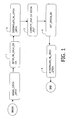
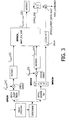
- Fig.3 represents a schematic architecture for an implementation of a RAKE receiver comprising the proposed DPDCH channel estimator using the algorithm summarized by steps 1-5 described in section 0.
- Fig.3 describes a portion of a single finger of the RAKE receiver, comprising:
- nearest neighbor interpolation will be adopted for the implementation of all the interpolation blocks INTERP1, INTERP2, and INTERP3, as it is shown to be a proper solution for this purpose in terms of complexity and performance trade-off.
- Nearest neighbor interpolation is the least complexity interpolation method. It actually saves complexity at the expense of a higher signal distortion than that resulting with more sophisticated interpolation techniques. However it can be shown that the actual amount of signal distortion yielded by that interpolation method is significantly below the noise and interference for practical ranges of signal, interference, and noise levels. Therefore, the additional signal distortion due to nearest neighbor interpolation is actually negligible compared with the effects of the noise and interference so as not affecting the receiver performances.
- Fig.4 represents a schematic architecture for an implementation of a RAKE receiver comprising the proposed DPDCH channel estimator using the algorithm summarized by steps 1-8 described in section 4.4.2.
- Fig.4 describes a portion of a single finger of the RAKE receiver, comprising:
- nearest neighbor interpolation will be adopted for the implementation of all the interpolation blocks INTERP1, INTERP2, and INTERP3, as is shown to be a proper solution for this purpose in terms of complexity and performance trade-off. Indeed the same considerations on nearest neighbor interpolation had done in section 0 on the joint CPICH-DPCH MAP DPDCH channel estimation algorithm hold in the case of the joint CPICH-DPCH low complexity DPDCH channel estimation algorithm as well.
- the present invention is not limited to the aforementioned UMTS application. It can be used within any application of DS-CDMA where the communication standard envisages the presence of two logical channels, i.e. a common pilot channel, comprising symbols or signal waveform(s) known at the mobile terminal UE, and a dedicated channel comprising unknown data symbols and, in a preferred but not limitative embodiment, also dedicated known pilot symbols or signal waveform(s).
- a common pilot channel comprising symbols or signal waveform(s) known at the mobile terminal UE
- a dedicated channel comprising unknown data symbols and, in a preferred but not limitative embodiment, also dedicated known pilot symbols or signal waveform(s).
- the present invention can be applied in the uplink communication, from the mobile terminal UE to the base station BS, when the mobile terminal UE the employs transmit beamforming.
- Said hardware or software items can be implemented in several manners, such as by means of wired electronic circuits or by means of an integrated circuit that is suitably programmed, respectively.
- the integrated circuit is to be part of a receiver that can be contained in a computer, in a mobile communication handset, in a base-station, or in any other communication system device.
- Said receiver comprises means of the receiver adapted to make all necessary operations to support a certain type of communication services (i.e. operations of de-scrambling, de-spreading, etc.) said means being hardware or software items as stated above.
- the first estimator within the receiver comprises maximum likelihood estimation means adapted to make the ML instantaneous estimates of steps 1 and 3, interpolation means adapted to make rate matching as in step 2, optimal MAP DPDCH channel multipath coefficient estimation means adapted to make the DPDCH estimates of step 4, interpolation means adapted to make rate matching as in step 5, as previously described, said means being hardware or software items as stated above.
- the second estimator within the receiver comprises maximum likelihood estimation means adapted to make the ML instantaneous estimates of steps 1 and 3, interpolation means adapted to make rate matching as in step 2, correlation estimation means adapted to make the correlations estimates of step 4, beamforming complex factor estimation means that are adapted to make the factor complex estimate of step 5, a first multipath coefficient estimation means adapted to make said CPICH multipath coefficient estimate of step 6, a second multipath coefficient estimation means that are adapted to make said DPDCH multipath coefficient estimate of step 7, interpolation means adapted to make rate matching as in step 8, as described previously, said means being hardware or software items as stated above stated.
- said means can be an assembly of items of hardware or software or both carrying out a function, or a single item carrying out several functions.
- the set of instructions may be loaded into the programming memory by reading a data carrier such as, for instance, a disk.
- a service provider can also make the set of instructions available via a communication network such as, for example, the Internet.
Landscapes
- Engineering & Computer Science (AREA)
- Power Engineering (AREA)
- Computer Networks & Wireless Communication (AREA)
- Signal Processing (AREA)
- Mobile Radio Communication Systems (AREA)
- Radio Transmission System (AREA)
- Noise Elimination (AREA)
- Radar Systems Or Details Thereof (AREA)
- Testing, Inspecting, Measuring Of Stereoscopic Televisions And Televisions (AREA)
- Monitoring And Testing Of Transmission In General (AREA)
- Investigating Or Analysing Materials By Optical Means (AREA)
Claims (15)
- Procédé pour l'estimation d'un canal de propagation en présence d'une formation de faisceau d'émission, prenant en compte la structure de deux canaux logiques et fondé sur une structure commune des canaux de propagation correspondants, ledit deuxième canal logique comprenant deux sous-canaux, lesdits canaux de propagation étant modélisés sous la forme d'une superposition linéaire d'un nombre fini de composantes de multi-trajets discrètes suivant un modèle stationnaire des diffusions non corrélé au sens large, une composante de multi-trajets comprenant un coefficient complexe de multi-trajets variable en fonction du temps et un retard, caractérisé par le fait que ledit canal de propagation correspond au premier sous-canal et que ledit procédé fournit des estimations de chaque coefficient complexe des composantes de multi-trajets, selon un critère d'optimisation de maximum a posteriori (MAP) prenant en compte la totalité des informations disponibles associées audits canaux logiques et aux canaux de propagation correspondants, grâce aux étapes de traitement suivantes :1. construction d'estimations instantanées des coefficients complexes de multi-trajets du canal selon le maximum de vraisemblance, ML, d'un deuxième canal logique et d'un premier canal logique,2. interpolation des estimations instantanées ML obtenues ci-dessus des coefficients complexes de multi-trajets du deuxième canal logique et du premier canal logique, à la fréquence symbole la plus faible desdits deuxième et premier canaux logiques,3. calcul d'un filtre de prédiction linéaire optimal selon un critère de maximum a posteriori MAP commun au deuxième et premier canal,4. filtrage des estimations instantanées ML des coefficients complexes de multi-trajets du deuxième et du premier canal logique interpolées, obtenues à l'étape 2 à l'aide dudit filtre de prédiction linéaire optimal, afin d'obtenir une estimation MAP du coefficient de multi-trajets du premier sous-canal, et5. interpolation de ladite estimation MAP du coefficient de multi-trajets du premier sous-canal à la fréquence symbole du deuxième canal logique lorsque ladite fréquence symbole est inférieure à la fréquence symbole du premier canal logique,dans lequel les étapes 1 à 5 sont répétées pour tous les coefficients complexes des composantes de multi-trajets.
- Procédé pour l'estimation d'un canal de propagation en présence d'une formation de faisceau d'émission, prenant en compte la structure de deux canaux logiques et fondé sur une structure commune des canaux de propagation correspondants, ledit deuxième canal logique comprenant deux sous-canaux, lesdits canaux de propagation étant modélisés sous la forme d'une superposition linéaire d'un nombre fini de composantes de multi-trajets discrètes suivant un modèle stationnaire des diffusions non corrélé au sens large, une composante de multi-trajets comprenant un coefficient complexe de multi-trajets variable en fonction du temps et un retard, caractérisé par le fait que ledit canal de propagation correspond au premier sous-canal et que ledit procédé fournit des estimations de chaque coefficient complexe des composantes de multi-trajets, prenant en compte la totalité des informations disponibles associées auxdits canaux logiques et aux canaux de propagation correspondants, grâce aux étapes de traitement suivantes :1. construction d'estimations instantanées des coefficients de multi-trajets du canal selon le maximum de vraisemblance, ML, d'un deuxième canal logique et d'un premier canal logique,2. interpolation desdites estimations instantanées ML des coefficients de multi-trajets, du premier canal logique et du deuxième canal logique, à la fréquence symbole la plus faible desdits deuxième et premier canaux logiques,3. construction d'une estimation du coefficient de multi-trajets du premier canal logique optimale selon le maximum a posteriori,4. construction d'une estimation de la corrélation croisée entre les estimations instantanées selon le maximum de vraisemblance des coefficients de multi-trajets du premier canal logique et du deuxième canal logique obtenues à l'étape 2 et d'une estimation de l'auto-corrélation des estimations instantanées selon le maximum de vraisemblance des coefficients de multi-trajets du premier canal logique des étapes 1 et 2 avec un retard de corrélation non nul pour l'annulation de bruit,5. construction d'une estimation d'un facteur complexe de formation de faisceau à partir des dites estimations de la corrélation croisée et de l'auto-corrélation,6. construction d'une estimation du coefficient de multi-trajets du premier sous-canal en tant que résultat des estimations obtenues aux étapes 3 et 5, et7. interpolation desdites estimations du coefficient de multi-trajets dudit premier canal à la fréquence symbole du deuxième canal logique lorsque ladite fréquence symbole est inférieure à la fréquence symbole du premier canal logique,dans lequel les étapes 1 à 7 sont répétées pour tous les coefficients complexes des composantes de multi-trajets.
- Procédé selon les revendications 1 ou 2, caractérisé par le fait que les estimations selon le maximum de vraisemblance des coefficients de multi-trajets du canal, pour le premier canal logique, sont calculées à partir de la connaissance a priori de certains symboles pilotes constituant ledit premier canal logique.
- Procédé selon les revendications 1 ou 2, caractérisé par le fait que les estimations selon le maximum de vraisemblance des coefficients de multi-trajets du canal, pour le deuxième canal logique ayant trait au deuxième sous-canal, sont calculées à partir d'une connaissance a priori de certains symboles pilotes constituant ledit deuxième sous-canal.
- Procédé selon les revendications 1 ou 2, caractérisé par le fait que les estimations selon le maximum de vraisemblance des coefficients de multi-trajets du deuxième canal logique, ayant trait au premier sous-canal, sont calculées par un mécanisme de décision directe.
- Procédé selon les revendications 1 ou 2, caractérisé par le fait que l'interpolation de l'étape 2 est réalisée par une interpolation au plus proche voisin.
- Procédé selon la revendication 1, caractérisé par le fait que le filtre de prédiction linéaire optimal est construit selon le critère d'optimisation de maximum a posteriori, fondé sur les estimations interpolées des coefficients de multi-trajets selon le maximum de vraisemblance, relatives audit premier et deuxième canal logique, afin de fournir une estimation optimale du coefficient de multi-trajets du premier sous-canal selon le maximum a posteriori conjoint du deuxième et du premier canal.
- Procédé selon la revendication 2, caractérisé par le fait que l'estimation selon le maximum de vraisemblance de la corrélation croisée du canal de propagation correspondant au deuxième canal et du canal de propagation correspondant au premier canal et qu'une estimation selon le maximum de vraisemblance de l'auto-corrélation du canal de propagation correspondant au premier canal logique sont calculées à partir des moments des échantillons des estimations selon le maximum de vraisemblance du premier et du deuxième canal des étapes 1 et 2.
- Procédé selon la revendication 2 pour le calcul de l'estimation dudit facteur complexe de formation de faisceau, caractérisé par le fait que les estimations selon le maximum de vraisemblance de la corrélation croisée du canal de propagation correspondant au deuxième canal logique et du canal de propagation correspondant au premier canal logique et de l'auto-corrélation du canal de propagation correspondant au premier canal logique, pour différents retards de corrélations, sont combinées de manière linéaire.
- Procédé selon la revendication 2, caractérisé par le fait que les estimations successives de la corrélation croisée du deuxième canal logique et du premier canal logique et de l'auto-corrélation du premier canal logique sont faites avec un retard fixé et subissent un filtrage passe-bas pour le calcul de l'estimation dudit facteur complexe.
- Procédé selon la revendication 2, caractérisé par le fait que l'estimation dudit facteur complexe est construite comme une combinaison linéaire des estimations de facteur complexe de formation de faisceau calculées comme le rapport des estimations de la corrélation croisée des canaux de propagation correspondants au deuxième canal logique et au premier canal logique et de l'auto-corrélation du canal de propagation correspondant au premier canal logique avec un certain retard.
- Procédé selon l'une des revendications 9, 10 ou 11, caractérisé par le fait que l'estimation dudit facteur complexe est limitée à un retard égal à 1.
- Estimateur pour l'estimation d'un canal de propagation en présence d'une formation de faisceau d'émission, prenant en compte la structure de deux canaux logiques désignés comme un canal commun et un canal physique dédié et fondé sur une structure commune des canaux de propagation correspondants, ledit canal physique dédié comprenant deux sous-canaux, lesdits canaux de propagation étant modélisés sous la forme d'une superposition linéaire d'un nombre fini de composantes de multi-trajets discrètes suivant un modèle stationnaire des diffusions non corrélé au sens large, une composante de multi-trajets comprenant un coefficient complexe de multi-trajets variable en fonction du temps et un retard, caractérisé par le fait que ledit canal de propagation correspond à l'estimation du premier sous-canal et que ledit estimateur comprend :• des moyens pour construire des estimations instantanées des coefficients complexes de multi-trajets du canal selon le maximum de vraisemblance, ML, d'un deuxième canal logique et d'un premier canal logique,• des moyens pour effectuer une interpolation des estimations instantanées ML obtenues ci-dessus des coefficients complexes de multi-trajets, du deuxième canal logique et du premier canal logique, à la fréquence symbole la plus faible desdits deuxième et premier canaux logiques,• des moyens pour construire un filtre de prédiction linéaire optimal selon un critère de maximum a posteriori MAP conjoint du deuxième et du premier canal,• des moyens pour obtenir une estimation du coefficient de multi-trajets du premier sous-canal par filtrage à l'aide dudit filtre de prédiction linéaire optimal, desdites estimations instantanées ML interpolées des coefficients complexes de multi-trajets du deuxième et du premier canal logique obtenues à l'étape 2, et• des moyens pour interpoler ladite estimation MAP du coefficient de multi-trajets du premier sous-canal à la fréquence symbole du deuxième canal logique lorsque ladite fréquence symbole est inférieure à la fréquence symbole du premier canal logique.
- Estimateur pour l'estimation d'un canal de propagation en présence d'une formation de faisceau d'émission, prenant en compte la structure de deux canaux logiques désignés comme un canal commun et un canal physique dédié et fondé sur une structure commune des canaux de propagation correspondants, ledit canal physique dédié comprenant deux sous-canaux, lesdits canaux de propagation étant modélisés sous la forme d'une superposition linéaire d'un nombre fini de composantes de multi-trajets discrètes suivant un modèle stationnaire des diffusions non corrélé au sens large, une composante de multi-trajets comprenant un coefficient complexe de multi-trajets variable en fonction du temps et un retard, caractérisé par le fait que ledit canal de propagation correspond au premier sous-canal et que ledit estimateur comprend :• des moyens pour construire des estimations instantanées des coefficients de multi-trajets du canal selon le maximum de vraisemblance, ML, d'un premier canal logique et d'un deuxième canal logique,• des moyens pour réaliser une interpolation des estimations instantanées ML obtenues ci-dessus des coefficients de multi-trajets du premier canal logique et du deuxième canal logique, à la fréquence symbole la plus faible desdits deuxième et premier canal logique,• des moyens pour construire une estimation des coefficients de multi-trajets du premier canal logique optimale selon le maximum a posteriori,• des moyens pour construire une estimation de la corrélation croisée entre les estimations instantanées selon le maximum de vraisemblance des coefficients de multi-trajets du premier canal logique et du deuxième canal logique obtenues dans lesdits moyens de réalisation de l'interpolation, et une estimation de l'auto-corrélation des estimations instantanées selon le maximum de vraisemblance des coefficients de multi-trajets du premier canal logique avec un retard de corrélation non nul pour l'annulation de bruit,• des moyens pour estimer un facteur complexe de formation de faisceau à partir desdites estimations de la corrélation croisée et de l'auto-corrélation,• des moyens pour construire une estimation du coefficient de multi-trajets d'un premier sous-canal en tant que résultat de l'estimation optimale selon le maximum a posteriori du coefficient de multi-trajets du premier canal logique et des estimations de la corrélation croisée et de l'auto-corrélation,• des moyens pour interpoler ladite estimation du coefficient de multi-trajets dudit premier sous-canal à la fréquence symbole du deuxième canal logique lorsque ladite fréquence symbole est inférieure à la fréquence symbole du premier canal logique.
- Récepteur étant configuré pour réaliser le procédé de la revendication 1 ou de la revendication 2 ou comportant un estimateur selon les revendications 13 ou 14.
Priority Applications (1)
| Application Number | Priority Date | Filing Date | Title |
|---|---|---|---|
| EP03748443A EP1559251B1 (fr) | 2002-10-30 | 2003-10-10 | Procedes d'estimation de canal en presence d'un faisceau de transmission mis en forme |
Applications Claiming Priority (6)
| Application Number | Priority Date | Filing Date | Title |
|---|---|---|---|
| EP02292709 | 2002-10-30 | ||
| EP02292709 | 2002-10-30 | ||
| EP03290294 | 2003-02-05 | ||
| EP03290294 | 2003-02-05 | ||
| EP03748443A EP1559251B1 (fr) | 2002-10-30 | 2003-10-10 | Procedes d'estimation de canal en presence d'un faisceau de transmission mis en forme |
| PCT/IB2003/004510 WO2004040869A1 (fr) | 2002-10-30 | 2003-10-10 | Procedes d'estimation de canal en presence d'un faisceau de transmission mis en forme |
Publications (2)
| Publication Number | Publication Date |
|---|---|
| EP1559251A1 EP1559251A1 (fr) | 2005-08-03 |
| EP1559251B1 true EP1559251B1 (fr) | 2008-09-17 |
Family
ID=32232210
Family Applications (1)
| Application Number | Title | Priority Date | Filing Date |
|---|---|---|---|
| EP03748443A Expired - Lifetime EP1559251B1 (fr) | 2002-10-30 | 2003-10-10 | Procedes d'estimation de canal en presence d'un faisceau de transmission mis en forme |
Country Status (8)
| Country | Link |
|---|---|
| US (1) | US8005159B2 (fr) |
| EP (1) | EP1559251B1 (fr) |
| JP (1) | JP4440211B2 (fr) |
| CN (1) | CN1708966B (fr) |
| AT (1) | ATE408950T1 (fr) |
| AU (1) | AU2003267748A1 (fr) |
| DE (1) | DE60323662D1 (fr) |
| WO (1) | WO2004040869A1 (fr) |
Families Citing this family (23)
| Publication number | Priority date | Publication date | Assignee | Title |
|---|---|---|---|---|
| US6970722B1 (en) * | 2002-08-22 | 2005-11-29 | Cisco Technology, Inc. | Array beamforming with wide nulls |
| US7437135B2 (en) | 2003-10-30 | 2008-10-14 | Interdigital Technology Corporation | Joint channel equalizer interference canceller advanced receiver |
| US7400692B2 (en) | 2004-01-14 | 2008-07-15 | Interdigital Technology Corporation | Telescoping window based equalization |
| KR100571138B1 (ko) * | 2004-01-15 | 2006-04-13 | 삼성전자주식회사 | 파일럿 신호를 이용한 빔 형성 방법, 이를 수행하기 위한장치 및 시스템 |
| US7359470B2 (en) * | 2004-09-10 | 2008-04-15 | Mitsubishi Electric Research Laboratories, Inc | Minimizing feedback rate for channel state information in MIMO systems |
| US8654899B2 (en) * | 2004-10-12 | 2014-02-18 | The Governors Of The University Of Alberta | Pilot symbol assisted modulation signal processing systems and methods |
| EP1882309B1 (fr) * | 2005-05-10 | 2016-11-09 | Qualcomm Incorporated | Synchronisation de stations de base au moyen d'un equipement utilisateur en mode multi-communication |
| US7599714B2 (en) * | 2005-09-30 | 2009-10-06 | Alcatel-Lucent Usa Inc. | Increasing the range of access point cells for a given throughput in a downlink of a wireless local area network |
| CN100352178C (zh) * | 2005-11-30 | 2007-11-28 | 中兴通讯股份有限公司 | 一种提高用户设备信道估计性能的方法 |
| WO2007119207A2 (fr) * | 2006-04-13 | 2007-10-25 | Nxp B.V. | Estimation de canal ameliore pour des canaux dedies utilisateurs |
| KR101123993B1 (ko) * | 2006-04-18 | 2012-04-16 | 인터디지탈 테크날러지 코포레이션 | 무선 통신 보호 방법 및 시스템 |
| US8009777B2 (en) * | 2007-06-15 | 2011-08-30 | Icera, Inc. | Processing data in a digital communications system |
| WO2009083978A2 (fr) * | 2007-12-31 | 2009-07-09 | Mobilicom Ltd. | Procédé, dispositif, et système de communication radio |
| KR100973013B1 (ko) * | 2008-12-22 | 2010-07-30 | 삼성전기주식회사 | Ofdm 시스템의 샘플링 주파수 옵셋 추정 장치 및 그 방법 |
| WO2011079210A1 (fr) | 2009-12-23 | 2011-06-30 | Interdigital Patent Holdings, Inc. | Réalisation de mesures dans des communications sans fil au moyen de multi-porteuses |
| CN102307165B (zh) * | 2011-08-29 | 2015-04-22 | 北京邮电大学 | 一种信道参数估计方法和系统 |
| CN104205694A (zh) * | 2012-03-02 | 2014-12-10 | 日本电气株式会社 | 信道估计方法和接收机 |
| US9294949B2 (en) * | 2012-08-28 | 2016-03-22 | Intel Deutschland Gmbh | Interference and noise estimation of a communications channel |
| WO2015030638A1 (fr) * | 2013-08-27 | 2015-03-05 | Telefonaktiebolaget L M Ericsson (Publ) | Positionnement de dispositifs sans fil |
| JP6453468B2 (ja) * | 2014-12-16 | 2019-01-16 | テレフオンアクチーボラゲット エルエム エリクソン(パブル) | Csi予測のための方法および構成 |
| CN108234365B (zh) * | 2018-02-26 | 2024-08-06 | 福建京奥通信技术有限公司 | Wcdma中继器下行信道参数估计系统及方法 |
| WO2019197030A1 (fr) | 2018-04-12 | 2019-10-17 | Huawei Technologies Co., Ltd. | Conversion de matrice de covariance de canal |
| US12452108B2 (en) * | 2022-01-27 | 2025-10-21 | Qualcomm Incorporated | Equivariant generative prior for inverse problems with unknown rotation |
Family Cites Families (6)
| Publication number | Priority date | Publication date | Assignee | Title |
|---|---|---|---|---|
| SE513657C2 (sv) * | 1993-06-24 | 2000-10-16 | Ericsson Telefon Ab L M | Sätt och anordning att vid digital signalöverföring estimera överförda symboler hos en mottagare |
| US6385185B1 (en) * | 1998-06-25 | 2002-05-07 | Lucent Technologies Inc. | Methods and apparatus for coherent detection of signals with orthogonal data modulation |
| US6831943B1 (en) * | 1999-08-13 | 2004-12-14 | Texas Instruments Incorporated | Code division multiple access wireless system with closed loop mode using ninety degree phase rotation and beamformer verification |
| US6839326B1 (en) * | 2000-09-26 | 2005-01-04 | Nokia Corporation | Antenna phase estimation algorithm for WCDMA closed loop transmitter antenna diversity system |
| CN1145289C (zh) * | 2001-02-28 | 2004-04-07 | 华为技术有限公司 | 无线通信系统中导频辅助判决反馈阵列接收机及其反馈方法 |
| US7149258B2 (en) * | 2001-11-28 | 2006-12-12 | Telefonaktiebolaget L M Ericsson (Publ) | Method and apparatus for estimation of phase offset between communication channels |
-
2003
- 2003-10-10 EP EP03748443A patent/EP1559251B1/fr not_active Expired - Lifetime
- 2003-10-10 JP JP2005501837A patent/JP4440211B2/ja not_active Expired - Fee Related
- 2003-10-10 DE DE60323662T patent/DE60323662D1/de not_active Expired - Lifetime
- 2003-10-10 WO PCT/IB2003/004510 patent/WO2004040869A1/fr not_active Ceased
- 2003-10-10 AT AT03748443T patent/ATE408950T1/de not_active IP Right Cessation
- 2003-10-10 US US10/532,912 patent/US8005159B2/en not_active Expired - Fee Related
- 2003-10-10 AU AU2003267748A patent/AU2003267748A1/en not_active Abandoned
- 2003-10-10 CN CN2003801025082A patent/CN1708966B/zh not_active Expired - Fee Related
Also Published As
| Publication number | Publication date |
|---|---|
| EP1559251A1 (fr) | 2005-08-03 |
| JP2006505227A (ja) | 2006-02-09 |
| ATE408950T1 (de) | 2008-10-15 |
| DE60323662D1 (de) | 2008-10-30 |
| CN1708966A (zh) | 2005-12-14 |
| JP4440211B2 (ja) | 2010-03-24 |
| CN1708966B (zh) | 2013-07-10 |
| US8005159B2 (en) | 2011-08-23 |
| AU2003267748A1 (en) | 2004-05-25 |
| US20060023653A1 (en) | 2006-02-02 |
| WO2004040869A1 (fr) | 2004-05-13 |
Similar Documents
| Publication | Publication Date | Title |
|---|---|---|
| US8005159B2 (en) | Methods for channel estimation in the presence of transmit beamforming | |
| US5875216A (en) | Weight generation in stationary interference and noise environments | |
| CN100397805C (zh) | 利用低复杂度天线阵列减少干扰 | |
| EP1082820B1 (fr) | Surveillance de retard d'une fenetre de recherche dans das systèmes de communication à acces multiple par code de répartition | |
| US7095814B2 (en) | Apparatus and method for very high performance space-time array reception processing using chip-level beamforming and fading rate adaptation | |
| CN100518008C (zh) | 在无线通信系统内用于确定组合器加权的装置和方法 | |
| US8098715B2 (en) | Method and apparatus for estimating impairment covariance matrices using unoccupied spreading codes | |
| US7965796B2 (en) | Channel estimation in a radio receiver | |
| US20070189362A1 (en) | Method and system for channel estimation, related receiver and computer program product | |
| JP2004503147A (ja) | 適応収束パラメータを用いたスマートアンテナ | |
| US7042926B2 (en) | Low complexity multiuser detector | |
| JP2007507977A (ja) | 複数の受信機アンテナ用のレイクベースcdma受信機 | |
| US7039094B2 (en) | Adaptive rake receiving apparatus constrained with at least one constraint for use in mobile communication system and method therefor | |
| US20090323874A1 (en) | Channel estimation using common and dedicated pilots | |
| KR100329110B1 (ko) | 칩 레벨 및 시간 기준 빔 형성 알고리즘을 적용한공간-시간 배열 수신시스템 | |
| US7995640B2 (en) | Dynamic interpolation location | |
| WO2002067453A1 (fr) | Syntonisation des doigts d'un recepteur rake | |
| KR20020039424A (ko) | 페이딩 적응형 초고성능 공간-시간 배열 수신 시스템 및그 방법 | |
| KR100406529B1 (ko) | 기준신호 발생 장치 및 그 방법과 그를 이용한 칩 레벨 빔형성기 기반의 스마트 안테나 기지국 시스템 및 그의 동작방법 | |
| Kim | Improved MUSIC algorithm for the code-timing estimation of DS-CDMA multipath-fading channels in multiantenna systems | |
| Falletti et al. | A novel blind adaptive space-time receiver for multi-code DS-CDMA | |
| Chen et al. | A RAKE receiver design for WCDMA FDD uplink with an RLS-based adaptive beamforming scheme | |
| Wei et al. | A semiblind adaptive antenna for WCDMA using a least-squares constant-modulus formulation | |
| KR101043759B1 (ko) | 스마트안테나를 사용하는 시스템에서 엘엠에스 알고리즘 적용을 위한 엘엠에스 에러값 결정방법 | |
| Abrardo | Non-coherent MLSE detection for CDMA multiple-antenna systems |
Legal Events
| Date | Code | Title | Description |
|---|---|---|---|
| PUAI | Public reference made under article 153(3) epc to a published international application that has entered the european phase |
Free format text: ORIGINAL CODE: 0009012 |
|
| 17P | Request for examination filed |
Effective date: 20050530 |
|
| AK | Designated contracting states |
Kind code of ref document: A1 Designated state(s): AT BE BG CH CY CZ DE DK EE ES FI FR GB GR HU IE IT LI LU MC NL PT RO SE SI SK TR |
|
| AX | Request for extension of the european patent |
Extension state: AL LT LV MK |
|
| DAX | Request for extension of the european patent (deleted) | ||
| RAP1 | Party data changed (applicant data changed or rights of an application transferred) |
Owner name: NXP B.V. |
|
| 17Q | First examination report despatched |
Effective date: 20070803 |
|
| GRAP | Despatch of communication of intention to grant a patent |
Free format text: ORIGINAL CODE: EPIDOSNIGR1 |
|
| GRAS | Grant fee paid |
Free format text: ORIGINAL CODE: EPIDOSNIGR3 |
|
| GRAA | (expected) grant |
Free format text: ORIGINAL CODE: 0009210 |
|
| AK | Designated contracting states |
Kind code of ref document: B1 Designated state(s): AT BE BG CH CY CZ DE DK EE ES FI FR GB GR HU IE IT LI LU MC NL PT RO SE SI SK TR |
|
| REG | Reference to a national code |
Ref country code: GB Ref legal event code: FG4D |
|
| REG | Reference to a national code |
Ref country code: CH Ref legal event code: EP |
|
| REG | Reference to a national code |
Ref country code: IE Ref legal event code: FG4D |
|
| REF | Corresponds to: |
Ref document number: 60323662 Country of ref document: DE Date of ref document: 20081030 Kind code of ref document: P |
|
| PG25 | Lapsed in a contracting state [announced via postgrant information from national office to epo] |
Ref country code: FI Free format text: LAPSE BECAUSE OF FAILURE TO SUBMIT A TRANSLATION OF THE DESCRIPTION OR TO PAY THE FEE WITHIN THE PRESCRIBED TIME-LIMIT Effective date: 20080917 Ref country code: SI Free format text: LAPSE BECAUSE OF FAILURE TO SUBMIT A TRANSLATION OF THE DESCRIPTION OR TO PAY THE FEE WITHIN THE PRESCRIBED TIME-LIMIT Effective date: 20080917 Ref country code: AT Free format text: LAPSE BECAUSE OF FAILURE TO SUBMIT A TRANSLATION OF THE DESCRIPTION OR TO PAY THE FEE WITHIN THE PRESCRIBED TIME-LIMIT Effective date: 20080917 |
|
| NLV1 | Nl: lapsed or annulled due to failure to fulfill the requirements of art. 29p and 29m of the patents act | ||
| PG25 | Lapsed in a contracting state [announced via postgrant information from national office to epo] |
Ref country code: BE Free format text: LAPSE BECAUSE OF FAILURE TO SUBMIT A TRANSLATION OF THE DESCRIPTION OR TO PAY THE FEE WITHIN THE PRESCRIBED TIME-LIMIT Effective date: 20080917 |
|
| PG25 | Lapsed in a contracting state [announced via postgrant information from national office to epo] |
Ref country code: ES Free format text: LAPSE BECAUSE OF FAILURE TO SUBMIT A TRANSLATION OF THE DESCRIPTION OR TO PAY THE FEE WITHIN THE PRESCRIBED TIME-LIMIT Effective date: 20081228 Ref country code: BG Free format text: LAPSE BECAUSE OF FAILURE TO SUBMIT A TRANSLATION OF THE DESCRIPTION OR TO PAY THE FEE WITHIN THE PRESCRIBED TIME-LIMIT Effective date: 20081217 |
|
| PG25 | Lapsed in a contracting state [announced via postgrant information from national office to epo] |
Ref country code: SK Free format text: LAPSE BECAUSE OF FAILURE TO SUBMIT A TRANSLATION OF THE DESCRIPTION OR TO PAY THE FEE WITHIN THE PRESCRIBED TIME-LIMIT Effective date: 20080917 Ref country code: RO Free format text: LAPSE BECAUSE OF FAILURE TO SUBMIT A TRANSLATION OF THE DESCRIPTION OR TO PAY THE FEE WITHIN THE PRESCRIBED TIME-LIMIT Effective date: 20080917 Ref country code: PT Free format text: LAPSE BECAUSE OF FAILURE TO SUBMIT A TRANSLATION OF THE DESCRIPTION OR TO PAY THE FEE WITHIN THE PRESCRIBED TIME-LIMIT Effective date: 20090217 Ref country code: MC Free format text: LAPSE BECAUSE OF NON-PAYMENT OF DUE FEES Effective date: 20081031 Ref country code: NL Free format text: LAPSE BECAUSE OF FAILURE TO SUBMIT A TRANSLATION OF THE DESCRIPTION OR TO PAY THE FEE WITHIN THE PRESCRIBED TIME-LIMIT Effective date: 20080917 Ref country code: CZ Free format text: LAPSE BECAUSE OF FAILURE TO SUBMIT A TRANSLATION OF THE DESCRIPTION OR TO PAY THE FEE WITHIN THE PRESCRIBED TIME-LIMIT Effective date: 20080917 |
|
| REG | Reference to a national code |
Ref country code: CH Ref legal event code: PL |
|
| PLBE | No opposition filed within time limit |
Free format text: ORIGINAL CODE: 0009261 |
|
| STAA | Information on the status of an ep patent application or granted ep patent |
Free format text: STATUS: NO OPPOSITION FILED WITHIN TIME LIMIT |
|
| PG25 | Lapsed in a contracting state [announced via postgrant information from national office to epo] |
Ref country code: EE Free format text: LAPSE BECAUSE OF FAILURE TO SUBMIT A TRANSLATION OF THE DESCRIPTION OR TO PAY THE FEE WITHIN THE PRESCRIBED TIME-LIMIT Effective date: 20080917 Ref country code: DK Free format text: LAPSE BECAUSE OF FAILURE TO SUBMIT A TRANSLATION OF THE DESCRIPTION OR TO PAY THE FEE WITHIN THE PRESCRIBED TIME-LIMIT Effective date: 20080917 |
|
| 26N | No opposition filed |
Effective date: 20090618 |
|
| PG25 | Lapsed in a contracting state [announced via postgrant information from national office to epo] |
Ref country code: IT Free format text: LAPSE BECAUSE OF FAILURE TO SUBMIT A TRANSLATION OF THE DESCRIPTION OR TO PAY THE FEE WITHIN THE PRESCRIBED TIME-LIMIT Effective date: 20080917 |
|
| PG25 | Lapsed in a contracting state [announced via postgrant information from national office to epo] |
Ref country code: IE Free format text: LAPSE BECAUSE OF NON-PAYMENT OF DUE FEES Effective date: 20081010 Ref country code: CH Free format text: LAPSE BECAUSE OF NON-PAYMENT OF DUE FEES Effective date: 20081031 Ref country code: LI Free format text: LAPSE BECAUSE OF NON-PAYMENT OF DUE FEES Effective date: 20081031 |
|
| PG25 | Lapsed in a contracting state [announced via postgrant information from national office to epo] |
Ref country code: SE Free format text: LAPSE BECAUSE OF FAILURE TO SUBMIT A TRANSLATION OF THE DESCRIPTION OR TO PAY THE FEE WITHIN THE PRESCRIBED TIME-LIMIT Effective date: 20081217 |
|
| PG25 | Lapsed in a contracting state [announced via postgrant information from national office to epo] |
Ref country code: CY Free format text: LAPSE BECAUSE OF FAILURE TO SUBMIT A TRANSLATION OF THE DESCRIPTION OR TO PAY THE FEE WITHIN THE PRESCRIBED TIME-LIMIT Effective date: 20080917 Ref country code: HU Free format text: LAPSE BECAUSE OF FAILURE TO SUBMIT A TRANSLATION OF THE DESCRIPTION OR TO PAY THE FEE WITHIN THE PRESCRIBED TIME-LIMIT Effective date: 20090318 Ref country code: LU Free format text: LAPSE BECAUSE OF NON-PAYMENT OF DUE FEES Effective date: 20081010 |
|
| PG25 | Lapsed in a contracting state [announced via postgrant information from national office to epo] |
Ref country code: TR Free format text: LAPSE BECAUSE OF FAILURE TO SUBMIT A TRANSLATION OF THE DESCRIPTION OR TO PAY THE FEE WITHIN THE PRESCRIBED TIME-LIMIT Effective date: 20080917 |
|
| PG25 | Lapsed in a contracting state [announced via postgrant information from national office to epo] |
Ref country code: GR Free format text: LAPSE BECAUSE OF FAILURE TO SUBMIT A TRANSLATION OF THE DESCRIPTION OR TO PAY THE FEE WITHIN THE PRESCRIBED TIME-LIMIT Effective date: 20081218 |
|
| REG | Reference to a national code |
Ref country code: GB Ref legal event code: 732E Free format text: REGISTERED BETWEEN 20140403 AND 20140409 |
|
| REG | Reference to a national code |
Ref country code: GB Ref legal event code: 732E Free format text: REGISTERED BETWEEN 20140515 AND 20140521 |
|
| REG | Reference to a national code |
Ref country code: FR Ref legal event code: TP Owner name: ERICSSON MODEMS SA, CH Effective date: 20140616 Ref country code: FR Ref legal event code: CD Owner name: ERICSSON MODEMS SA, CH Effective date: 20140616 |
|
| REG | Reference to a national code |
Ref country code: DE Ref legal event code: R082 Ref document number: 60323662 Country of ref document: DE Representative=s name: HOSENTHIEN-HELD UND DR. HELD, DE |
|
| REG | Reference to a national code |
Ref country code: DE Ref legal event code: R082 Ref document number: 60323662 Country of ref document: DE Representative=s name: HOSENTHIEN-HELD UND DR. HELD, DE Effective date: 20140723 Ref country code: DE Ref legal event code: R081 Ref document number: 60323662 Country of ref document: DE Owner name: ERICSSON MODEMS SA, CH Free format text: FORMER OWNER: NXP B.V., EINDHOVEN, NL Effective date: 20140723 Ref country code: DE Ref legal event code: R081 Ref document number: 60323662 Country of ref document: DE Owner name: TELEFONAKTIEBOLAGET L M ERICSSON (PUBL), SE Free format text: FORMER OWNER: NXP B.V., EINDHOVEN, NL Effective date: 20140723 Ref country code: DE Ref legal event code: R082 Ref document number: 60323662 Country of ref document: DE Representative=s name: BURCHARDI, THOMAS, DIPL.-ING. UNIV., DE Effective date: 20140723 |
|
| REG | Reference to a national code |
Ref country code: FR Ref legal event code: PLFP Year of fee payment: 13 |
|
| REG | Reference to a national code |
Ref country code: GB Ref legal event code: 732E Free format text: REGISTERED BETWEEN 20151001 AND 20151007 |
|
| REG | Reference to a national code |
Ref country code: DE Ref legal event code: R082 Ref document number: 60323662 Country of ref document: DE Representative=s name: HOSENTHIEN-HELD UND DR. HELD, DE Ref country code: DE Ref legal event code: R081 Ref document number: 60323662 Country of ref document: DE Owner name: TELEFONAKTIEBOLAGET L M ERICSSON (PUBL), SE Free format text: FORMER OWNER: ERICSSON MODEMS SA, LE GRAND-SACONNEX, CH Ref country code: DE Ref legal event code: R082 Ref document number: 60323662 Country of ref document: DE Representative=s name: BURCHARDI, THOMAS, DIPL.-ING. UNIV., DE |
|
| REG | Reference to a national code |
Ref country code: DE Ref legal event code: R082 Ref document number: 60323662 Country of ref document: DE Representative=s name: BURCHARDI, THOMAS, DIPL.-ING. UNIV., DE |
|
| REG | Reference to a national code |
Ref country code: FR Ref legal event code: TP Owner name: TELEFONAKTIEBOLAGET L M ERICSSON, SE Effective date: 20160121 |
|
| REG | Reference to a national code |
Ref country code: FR Ref legal event code: PLFP Year of fee payment: 14 |
|
| REG | Reference to a national code |
Ref country code: FR Ref legal event code: PLFP Year of fee payment: 15 |
|
| REG | Reference to a national code |
Ref country code: FR Ref legal event code: PLFP Year of fee payment: 16 |
|
| PGFP | Annual fee paid to national office [announced via postgrant information from national office to epo] |
Ref country code: DE Payment date: 20181029 Year of fee payment: 16 |
|
| PGFP | Annual fee paid to national office [announced via postgrant information from national office to epo] |
Ref country code: FR Payment date: 20181025 Year of fee payment: 16 Ref country code: GB Payment date: 20181029 Year of fee payment: 16 |
|
| REG | Reference to a national code |
Ref country code: DE Ref legal event code: R119 Ref document number: 60323662 Country of ref document: DE |
|
| PG25 | Lapsed in a contracting state [announced via postgrant information from national office to epo] |
Ref country code: DE Free format text: LAPSE BECAUSE OF NON-PAYMENT OF DUE FEES Effective date: 20200501 |
|
| GBPC | Gb: european patent ceased through non-payment of renewal fee |
Effective date: 20191010 |
|
| PG25 | Lapsed in a contracting state [announced via postgrant information from national office to epo] |
Ref country code: FR Free format text: LAPSE BECAUSE OF NON-PAYMENT OF DUE FEES Effective date: 20191031 Ref country code: GB Free format text: LAPSE BECAUSE OF NON-PAYMENT OF DUE FEES Effective date: 20191010 |