EP1559314B1 - Dispositif et méthode de nettoyage d'une installation de traite - Google Patents
Dispositif et méthode de nettoyage d'une installation de traite Download PDFInfo
- Publication number
- EP1559314B1 EP1559314B1 EP04078420A EP04078420A EP1559314B1 EP 1559314 B1 EP1559314 B1 EP 1559314B1 EP 04078420 A EP04078420 A EP 04078420A EP 04078420 A EP04078420 A EP 04078420A EP 1559314 B1 EP1559314 B1 EP 1559314B1
- Authority
- EP
- European Patent Office
- Prior art keywords
- milk
- cleaning
- period
- filter element
- line
- Prior art date
- Legal status (The legal status is an assumption and is not a legal conclusion. Google has not performed a legal analysis and makes no representation as to the accuracy of the status listed.)
- Expired - Lifetime
Links
- 238000004140 cleaning Methods 0.000 title claims abstract description 81
- 238000009434 installation Methods 0.000 title claims abstract description 19
- 238000000034 method Methods 0.000 title claims description 13
- 239000008267 milk Substances 0.000 claims abstract description 116
- 210000004080 milk Anatomy 0.000 claims abstract description 116
- 235000013336 milk Nutrition 0.000 claims abstract description 116
- 238000007599 discharging Methods 0.000 claims abstract description 8
- 239000008237 rinsing water Substances 0.000 claims abstract description 8
- 235000020243 first infant milk formula Nutrition 0.000 claims abstract description 6
- 238000007664 blowing Methods 0.000 claims description 8
- 239000000126 substance Substances 0.000 claims description 4
- 239000002245 particle Substances 0.000 description 3
- 230000002349 favourable effect Effects 0.000 description 2
- 239000012530 fluid Substances 0.000 description 2
- XLYOFNOQVPJJNP-UHFFFAOYSA-N water Substances O XLYOFNOQVPJJNP-UHFFFAOYSA-N 0.000 description 2
- 210000003608 fece Anatomy 0.000 description 1
- 238000001914 filtration Methods 0.000 description 1
- 210000004209 hair Anatomy 0.000 description 1
Images

Classifications
-
- A—HUMAN NECESSITIES
- A01—AGRICULTURE; FORESTRY; ANIMAL HUSBANDRY; HUNTING; TRAPPING; FISHING
- A01J—MANUFACTURE OF DAIRY PRODUCTS
- A01J7/00—Accessories for milking machines or devices
- A01J7/02—Accessories for milking machines or devices for cleaning or sanitising milking machines or devices
-
- A—HUMAN NECESSITIES
- A01—AGRICULTURE; FORESTRY; ANIMAL HUSBANDRY; HUNTING; TRAPPING; FISHING
- A01J—MANUFACTURE OF DAIRY PRODUCTS
- A01J7/00—Accessories for milking machines or devices
- A01J7/02—Accessories for milking machines or devices for cleaning or sanitising milking machines or devices
- A01J7/022—Clean-in-Place Systems, i.e. CIP, for cleaning the complete milking installation in place
Definitions
- the invention relates to a device for cleaning a milking installation according to the preamble of claim 1 see e.g. document NL-C-1 016 817.
- the preamble of claim 1 discloses a device for cleaning a milking installation, in which device the cleaning of the milking installation, in particular the replacement of the milk filter, can take place in a simple manner at convenient points of time.
- a device for cleaning a milking installation of the above-described type comprises the features of the preamble of claim 1.
- a milk filter or milk filter element needs not to be replaced before the milking can be continued.
- the valve element is automatically switchable, the switching times being in particular pre-adjustable, it is not necessary for a farmer to be present, and the replacement of the milk filter element can take place before the next cleaning at a point of time convenient to the farmer.
- the device is preferably provided with a blowing device for blowing through the relevant milk filter element. It is further advantageous for the device to be provided with a main cleaning device, such as a heat cleaning device or a chemical cleaning device for cleaning with the aid of chemicals, for performing, during a main cleaning period, a main cleaning of the milk line and the relevant milk filter element, the cleaning period comprising the main cleaning period.
- a main cleaning device such as a heat cleaning device or a chemical cleaning device for cleaning with the aid of chemicals
- the control unit is designed in such a way that the operation of the valve element takes place after a minimum threshold part of the rinsing period inputted into a memory of the control unit has elapsed.
- the minimum threshold part amounts to approximately 50% of the rinsing period.
- the control unit is designed in such a way that the operation of the valve element takes place before a maximum threshold part of the main cleaning period inputted into the memory of the control unit has elapsed.
- the maximum threshold part preferably amounts to approximately 20% of the main cleaning period.
- the main cleaning performed for example with hot water or steam, is performed through a clean filter, resulting in a better cleaning of the parts between a filter element and the milk tank.
- the invention is in particular applicable to a milking installation with a milking robot for automatically connecting a teat cup to a teat of an animal.
- the invention also relates to a method of cleaning according to claim 15.
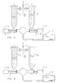
- FIG. 1 shows diagrammatically a part of a device for cleaning a milking installation for milking an animal, which part is relevant to the invention.
- the milking installation comprises a milk line 1 for discharging milk to a milk tank 2 or an other milk container.
- a milk filter is included in the milk line 1, which milk filter is designed as a first milk filter element 3 and a second milk filter element 4 arranged parallel to each other.
- arranged parallel to each other used in the present description is meant a parallel circuit generally known in fluid mechanics, without any undesired limitation with respect to the spatial configuration.
- the device is further provided with a non-shown blowing device, known per se, for blowing through the milk filter elements, with a non-shown rinsing water device, known per se, for rinsing, during a rinsing period, the milk line 1 and the relevant milk filter element 3, 4 with rinsing water, and with a main cleaning device, known per se, in the embodiment shown a heat cleaning device for performing, during a heat cleaning period (i.e. the main cleaning period), a heat cleaning of the milk line 1 and the relevant milk filter element 3, 4.
- the heat cleaning may be performed, for example, with hot water or with steam.
- a valve element 5 is included in the milk line 1, which valve element 5 is preferably automatically switchable by a non-shown control unit.
- the valve element 5 may comprise, for example, a three-way valve, or two butterfly valves or an equivalent valve device.
- the valve element 5 is capable of being put into a first position for connecting the milk line 1 to the first milk filter element 3 and into a second position for connecting the milk line 1 to the second milk filter element 4.
- the control unit is suitable for operating during at least one cleaning, and preferably during each cleaning, the switchable valve element 5 for connecting the milk line 1 to the other milk filter element.
- the operation of the valve element 5 by the control unit is such, in other words the switching times are such, that the switching takes place after a minimum threshold part of the rinsing period, inputted into a memory of the control unit, has elapsed, and before a maximum threshold part of the heat cleaning period, inputted into the memory of the control unit, has elapsed. It has been found in practice that a minimum threshold part of approximately 50% of the rinsing period and a maximum threshold part of approximately 20% of the heat cleaning period provide excellent results.
- Each milk filter element 3, 4 is connectable to the milk tank 2 with the aid of a relevant rinsing valve 6, respectively 7, via a line.
- the rinsing valves 6, 7 are preferably automatically controllable by means of the control unit.
- the rinsing valves 6, 7 are connected to the connecting piece of the milk tank 2. In this manner it is possible to clean the rinsing valves simultaneously with the cleaning of the milk tank.
- FIG 1 shows the situation in which the milk is discharged via the first milk filter element 3 to the milk tank 2. In this position, also the blowing out of the milk line 1 and the milk filter element 3 in the milk tank 2 takes place, so that the milk residues can be removed from the milk line 1 and the milk filter element 3.
- the position of the rinsing valve 6 is such that rinsing water runs off via the discharge 8. This position is used during the first threshold part of the rinsing period and during the maximum threshold part of the heat cleaning period. Then the valve element 5 and the rinsing valves 6, 7 are put into such a position that at least a part of the heat cleaning takes place through a, previously disposed, clean milk filter element 4 (as shown in Figure 3). The fluid used for the heat cleaning is discharged via the discharge 9.
- Figure 4 shows the situation in which milk is discharged via the second milk filter element 4 to the milk tank 2. Now the farmer is able to select, until the next cleaning, a favourable time for replacing the milk filter element 3, or a component thereof, such as a filter sock, by a clean filter.
- this is possible in a simple manner owing to the fact that the filter body is tube-shaped and has an upper end that is adapted to be opened, so that the filter element disposed in the filter body can be removed in a simple manner by lifting it from the filter body.
- the inner side of the filter body can be cleaned in a simple manner owing to the fact that in an embodiment of a device according to the invention the filter body is disposed above the rinsing valve and the discharge is disposed in the immediate vicinity of the rinsing valve.
- each filter element may be designed as a cylindrical mesh element, the milk flowing from the outer side to the inner side of the mesh element for the purpose of filtration.
- each filter element may be designed, however, as one or more substantially disc-shaped mesh elements extending substantially transversely to the milk flow, so that the milk flows through the disc-shaped mesh elements.
- These disc-shaped mesh elements are preferably rotatable, so that the mesh elements are capable of being cleaned in counterflow.
- contaminating parts may still remain on the mesh element after the cleaning.
- These contaminated particles are preferably removed by making use of a scraper that is movable along the mesh element. Such a scraper may be integrated in the milk filter.
- the disc-shaped mesh element constitutes part of an arc segment and if the scraper is a rotatable scraper that moves by rotation along the surface of the mesh element.
- the axis of rotation of the scraper preferably coincides with the axis of rotation of the mesh element.
- mesh also other elements provided with holes, such as, for example, perforated plates, may be used.
Landscapes
- Life Sciences & Earth Sciences (AREA)
- Animal Husbandry (AREA)
- Environmental Sciences (AREA)
- Cleaning In General (AREA)
- Apparatus For Making Beverages (AREA)
- Dairy Products (AREA)
- Extrusion Moulding Of Plastics Or The Like (AREA)
- Cleaning By Liquid Or Steam (AREA)
Claims (22)
- Dispositif pour nettoyer, au cours d'une phase de nettoyage, une;installation de traite pour traire un animal, laquelle installation de traite comprend une canalisation à lait (1) pour l'évacuation du lait vers une cuve de lait (2), un filtre à lait étant compris dans ladite canalisation à lait, lequel dispositif est pourvu d'un dispositif de rinçage à l'eau pour rincer, au cours d'une phase de rinçage, la canalisation à lait et le filtre à lait avec une eau de rinçage, la phase de nettoyage comprenant la phase de rinçage, ledit filtre à lait comprenant une première (3) et une seconde pièces de filtre à lait (4) agencées parallèlement l'une à l'autre, avec un élément de valve commutable (5) compris dans la canalisation à lait, lequel élément de valve est capable d'être mis dans une première position pour raccorder la canalisation à lait à la première pièce du filtre à lait et dans une seconde position pour raccorder la canalisation à lait à la seconde pièce du filtre à lait, le dispositif étant pourvu d'une unité de commande pour faire fonctionner l'élément de valve commutable pendant au moins une phase de nettoyage pour raccorder la canalisation à lait à l'autre pièce du filtre à lait,
caractérisé en ce que l'unité de commande est conçue de telle manière que le fonctionnement de l'élément de valve (5) a lieu après qu'environ 50 % de la phase de rinçage entrée dans une mémoire de l'unité de commande se sont écoulés. - Dispositif selon la revendication 1,
caractérisé en ce que le dispositif est pourvu d'un dispositif de soufflage pour souffler dans la pièce du filtre à lait appropriée. - Dispositif selon la revendication 1 ou 2,
caractérisé en ce que le dispositif est pourvu d'un dispositif de nettoyage principal, tel qu'un dispositif de nettoyage thermique ou un dispositif de nettoyage chimique pour un nettoyage à l'aide de produits chimiques, pour effectuer, durant une phase de nettoyage principal, un nettoyage principal de la canalisation à lait et des pièces du filtre à lait appropriées, la phase de nettoyage comprenant la phase de nettoyage principal. - Dispositif selon la revendication 3,
caractérisé en ce que l'unité de commande est conçue de telle manière que le fonctionnement de l'élément de valve a lieu avant qu'une partie de seuil maximal de la phase de nettoyage principal entrée dans la mémoire de l'unité de commande ne se soit écoulée. - Dispositif selon la revendication 4,
caractérisé en ce que la partie de seuil maximal s'élève à environ 20 % de la phase de nettoyage principal. - Dispositif selon l'une quelconque des revendications précédentes, caractérisé en ce que l'installation de traite comprend un robot de traite pour raccorder automatiquement un gobelet-trayeur au trayon d'un animal.
- Dispositif selon l'une quelconque des revendications précédentes, caractérisé en ce que l'élément de valve est commutable automatiquement.
- Dispositif selon l'une quelconque des revendications précédentes, caractérisé en ce qu'une pièce de filtre est conçue comme un élément de maille cylindrique.
- Dispositif selon l'une quelconque des revendications 1 à 7, caractérisé en ce qu'une pièce de filtre comprend un ou plusieurs éléments de maille essentiellement en forme de disque s'étendant essentiellement de manière transversale par rapport au flux de lait.
- Dispositif selon la revendication 9, caractérisé en ce qu'un élément de maille est disposé de façon pivotante autour d'un axe de rotation.
- Dispositif selon la revendication 8, 9 ou 10, caractérisé en ce que le dispositif comprend un racloir qui est mobile le long de l'élément de maille.
- Dispositif selon la revendication 11, caractérisé en ce que le racloir est intégré dans le filtre à lait.
- Dispositif selon les revendications 10 et 11 ou les revendications 10 et 13, caractérisé en ce que l'élément de maille en forme de disque fait partie d'un segment d'arc et en ce que le racloir est un racloir pivotant qui est mobile par rotation autour d'un axe de rotation le long de la surface de l'élément de maille.
- Dispositif selon la revendication 13, caractérisé en ce que l'axe de rotation du racloir coïncide avec l'axe de rotation de l'élément de maille.
- Méthode pour nettoyer, au cours d'une phase de nettoyage, une installation de traite pour traire un animal, laquelle installation de traite comprend une canalisation à lait (1) pour l'évacuation du lait vers une cuve de lait (2), un filtre à lait étant compris dans ladite canalisation à lait, laquelle méthode comprend les étapes successives consistant à :évacuer le lait par la canalisation à lait une première fois,effectuer un premier nettoyage de la canalisation à lait,évacuer le lait par la canalisation à lait une seconde fois,effectuer un second nettoyage de la canalisation à lait,un nettoyage comprenant le rinçage, au cours d'une phase de rinçage, de la canalisation à lait et du filtre à lait avec de l'eau de rinçage, la phase de nettoyage comprenant la phase de rinçage,ladite méthode comprenant en outre les étapes consistant à utiliser comme filtre à lait une première (3) et une seconde pièces de filtre (4) agencées parallèlement l'une à l'autre, disposer dans la canalisation à lait et utiliser un élément de valve commutable (5), lequel élément de valve est capable d'être mis dans une première position pour raccorder la canalisation à lait à la première pièce du filtre à lait dans le but d'évacuer le lait la première fois, et dans une seconde position pour raccorder la canalisation à lait à la seconde pièce du filtre à lait dans le but d'évacuer le lait la seconde fois, l'élément de valve commutable étant en fonctionnement pendant au moins une phase de nettoyage pour raccorder la canalisation à lait à l'autre pièce du filtre à lait,caractérisée en ce que le fonctionnement de l'élément de valve (5) a lieu après qu'environ 50 % de la phase de rinçage se sont écoulés.
- Méthode selon la revendication 15, caractérisée en ce que le nettoyage comprend l'étape consistant à souffler à travers la pièce du filtre à lait appropriée.
- Méthode selon la revendication 15 ou 16, caractérisée en ce que le nettoyage comprend l'étape consistant à effectuer, au cours d'une phase de nettoyage principal, un nettoyage principal de la canalisation à lait et de la pièce du filtre à lait appropriée, la phase de nettoyage comprenant la phase de nettoyage principal.
- Méthode selon la revendication 17, caractérisée en ce que le fonctionnement de l'élément de valve a lieu avant qu'une partie de seuil maximal de la phase de nettoyage principal ne se soit écoulée.
- Méthode selon la revendication 18, caractérisée en ce qu'une valeur d'environ 20 % est choisie comme partie de seuil maximal de la phase de nettoyage principal.
- Méthode selon l'une quelconque des revendications 15 à 19, caractérisée en ce que, après le fonctionnement de l'élément de valve et avant le nettoyage consécutif, la pièce du filtre ou une partie de celle-ci, qui n'est pas connectée à la canalisation à lait est remplacée.
- Méthode selon l'une quelconque des revendications 15 à 20, caractérisée en ce que la traite d'un animal comprend l'étape consistant à raccorder automatiquement un gobelet trayeur au trayon de l'animal.
- Méthode selon l'une quelconque des revendications 15 à 21, caractérisée en ce que le fonctionnement de l'élément de valve est exécuté automatiquement.
Applications Claiming Priority (6)
| Application Number | Priority Date | Filing Date | Title |
|---|---|---|---|
| NL1025348A NL1025348C2 (nl) | 2004-01-29 | 2004-01-29 | Inrichting en werkwijze voor het reinigen van een melkinstallatie. |
| NL1025348 | 2004-01-29 | ||
| NL1025395 | 2004-02-04 | ||
| NL1025395A NL1025395C1 (nl) | 2004-01-29 | 2004-02-04 | Inrichting en werkwijze voor het reinigen van een melkinstallatie. |
| NL1027439A NL1027439C1 (nl) | 2004-01-29 | 2004-11-08 | Inrichting en werkwijze voor het reinigen van een melkinstallatie. |
| NL1027439 | 2004-11-08 |
Publications (2)
| Publication Number | Publication Date |
|---|---|
| EP1559314A1 EP1559314A1 (fr) | 2005-08-03 |
| EP1559314B1 true EP1559314B1 (fr) | 2007-02-14 |
Family
ID=34657770
Family Applications (1)
| Application Number | Title | Priority Date | Filing Date |
|---|---|---|---|
| EP04078420A Expired - Lifetime EP1559314B1 (fr) | 2004-01-29 | 2004-12-17 | Dispositif et méthode de nettoyage d'une installation de traite |
Country Status (5)
| Country | Link |
|---|---|
| EP (1) | EP1559314B1 (fr) |
| AT (1) | ATE353556T1 (fr) |
| DE (1) | DE602004004748T2 (fr) |
| DK (1) | DK1559314T3 (fr) |
| NL (1) | NL1027439C1 (fr) |
Cited By (1)
| Publication number | Priority date | Publication date | Assignee | Title |
|---|---|---|---|---|
| US9332726B2 (en) | 2010-11-16 | 2016-05-10 | Delaval Holding Ab | Milking system, and a method for operating a milking system |
Families Citing this family (4)
| Publication number | Priority date | Publication date | Assignee | Title |
|---|---|---|---|---|
| CN105265321A (zh) * | 2015-11-23 | 2016-01-27 | 綦江县万兴肉牛养殖场 | 带清洗和臭氧杀菌功能的挤奶系统 |
| CA3191308A1 (fr) * | 2020-09-03 | 2022-03-10 | Lely Patent N.V. | Dispositif de traite dote d'un filtre a lait |
| NL2028864B1 (nl) * | 2021-07-28 | 2023-02-02 | Lely Patent Nv | Melkinrichting voorzien van een melkfilter |
| NL2030195B1 (nl) * | 2021-12-20 | 2023-06-28 | Lely Patent Nv | Melkinrichting |
Family Cites Families (7)
| Publication number | Priority date | Publication date | Assignee | Title |
|---|---|---|---|---|
| SU1050613A1 (ru) * | 1982-06-11 | 1983-10-30 | Центральный Научно-Исследовательский И Проектно-Технологический Институт Механизации И Электрификации Животноводства Южной Зоны Ссср | Устройство дл очистки жидкости |
| GB2264156B (en) * | 1992-02-13 | 1995-10-25 | Mitchell Richard Anderson | Milk pipeline washing system |
| NL9300143A (nl) * | 1993-01-26 | 1994-08-16 | Lely Nv C Van Der | Melkinrichting. |
| NL9301985A (nl) * | 1993-11-17 | 1995-06-16 | Texas Industries Inc | Melkmachine. |
| NL9402010A (nl) * | 1994-11-30 | 1996-07-01 | Maasland Nv | Inrichting voor het melken van dieren. |
| NL1010829C2 (nl) * | 1998-12-16 | 2000-06-19 | Prolion Bv | Inrichting en werkwijze voor het melken van dieren en een vervuilingsmeter. |
| NL1016817C2 (nl) * | 2000-12-06 | 2002-06-07 | Prolion Bv | Melkinrichting en werkwijze voor het reinigen van de melkinrichting. |
-
2004
- 2004-11-08 NL NL1027439A patent/NL1027439C1/nl not_active IP Right Cessation
- 2004-12-17 AT AT04078420T patent/ATE353556T1/de not_active IP Right Cessation
- 2004-12-17 DK DK04078420T patent/DK1559314T3/da active
- 2004-12-17 EP EP04078420A patent/EP1559314B1/fr not_active Expired - Lifetime
- 2004-12-17 DE DE602004004748T patent/DE602004004748T2/de not_active Expired - Lifetime
Cited By (1)
| Publication number | Priority date | Publication date | Assignee | Title |
|---|---|---|---|---|
| US9332726B2 (en) | 2010-11-16 | 2016-05-10 | Delaval Holding Ab | Milking system, and a method for operating a milking system |
Also Published As
| Publication number | Publication date |
|---|---|
| DE602004004748T2 (de) | 2007-11-22 |
| DK1559314T3 (da) | 2007-06-11 |
| DE602004004748D1 (de) | 2007-03-29 |
| EP1559314A1 (fr) | 2005-08-03 |
| NL1027439C1 (nl) | 2005-08-01 |
| ATE353556T1 (de) | 2007-03-15 |
Similar Documents
| Publication | Publication Date | Title |
|---|---|---|
| DE69914516T2 (de) | Gerät zur Reinigung und Desinfektion/Sterilisation eines Endoskops | |
| US20110155068A1 (en) | Cleaning system for milking cups | |
| EP1559314B1 (fr) | Dispositif et méthode de nettoyage d'une installation de traite | |
| US6203714B1 (en) | Device for filtering a liquid and method for disinfecting such a device | |
| AU1472602A (en) | A cleaning device | |
| US6645310B2 (en) | Method for cleaning industrial pipe systems | |
| KR100361116B1 (ko) | 이동형 음식물용기 자동세척장치 및 그를 이용한 세척방법 | |
| AU2006246037B2 (en) | Process and system for the disposal of excretion containers | |
| EP0626130B1 (fr) | Dispositif de traite d'animaux | |
| EP0558919A1 (fr) | Procédé et dispositif pour nettoyer un filtre | |
| NL1025348C2 (nl) | Inrichting en werkwijze voor het reinigen van een melkinstallatie. | |
| CN215089274U (zh) | 流化床的消毒清洗装置 | |
| KR100558761B1 (ko) | 회전식 케이지 자동 세척기 | |
| NL1016817C2 (nl) | Melkinrichting en werkwijze voor het reinigen van de melkinrichting. | |
| US2714893A (en) | Direct washing, flushing, and sterilizing system of stainless steel milk machine pipe lines on farms | |
| KR200436035Y1 (ko) | 생활하수의 슬러지 처리장치 | |
| CN207680178U (zh) | 便于卸料清洗的过滤罐 | |
| CN210026702U (zh) | 一种墨盒的清洗供排控制系统 | |
| KR101987471B1 (ko) | 싱크대용 악취방지장치 | |
| AU2022424306A1 (en) | Milking device with a cleaning unit | |
| WO2025126051A1 (fr) | Procédé de nettoyage d'un filtre à lait et système de traite pour le procédé | |
| CH646405A5 (de) | Vorrichtung zum belueften von wasser. | |
| JP4146248B2 (ja) | 浴槽水の処理方法 | |
| JPS63111911A (ja) | 洗浄・消毒機能を有する自動逆洗システム | |
| US7631652B2 (en) | Flush rinse apparatus for electroplating operations |
Legal Events
| Date | Code | Title | Description |
|---|---|---|---|
| PUAI | Public reference made under article 153(3) epc to a published international application that has entered the european phase |
Free format text: ORIGINAL CODE: 0009012 |
|
| AK | Designated contracting states |
Kind code of ref document: A1 Designated state(s): AT BE BG CH CY CZ DE DK EE ES FI FR GB GR HU IE IS IT LI LT LU MC NL PL PT RO SE SI SK TR |
|
| AX | Request for extension of the european patent |
Extension state: AL BA HR LV MK YU |
|
| 17P | Request for examination filed |
Effective date: 20051206 |
|
| AKX | Designation fees paid |
Designated state(s): AT BE BG CH CY CZ DE DK EE ES FI FR GB GR HU IE IS IT LI LT LU MC NL PL PT RO SE SI SK TR |
|
| GRAP | Despatch of communication of intention to grant a patent |
Free format text: ORIGINAL CODE: EPIDOSNIGR1 |
|
| GRAS | Grant fee paid |
Free format text: ORIGINAL CODE: EPIDOSNIGR3 |
|
| GRAA | (expected) grant |
Free format text: ORIGINAL CODE: 0009210 |
|
| AK | Designated contracting states |
Kind code of ref document: B1 Designated state(s): AT BE BG CH CY CZ DE DK EE ES FI FR GB GR HU IE IS IT LI LT LU MC NL PL PT RO SE SI SK TR |
|
| PG25 | Lapsed in a contracting state [announced via postgrant information from national office to epo] |
Ref country code: CH Free format text: LAPSE BECAUSE OF FAILURE TO SUBMIT A TRANSLATION OF THE DESCRIPTION OR TO PAY THE FEE WITHIN THE PRESCRIBED TIME-LIMIT Effective date: 20070214 Ref country code: AT Free format text: LAPSE BECAUSE OF FAILURE TO SUBMIT A TRANSLATION OF THE DESCRIPTION OR TO PAY THE FEE WITHIN THE PRESCRIBED TIME-LIMIT Effective date: 20070214 Ref country code: LI Free format text: LAPSE BECAUSE OF FAILURE TO SUBMIT A TRANSLATION OF THE DESCRIPTION OR TO PAY THE FEE WITHIN THE PRESCRIBED TIME-LIMIT Effective date: 20070214 Ref country code: BE Free format text: LAPSE BECAUSE OF FAILURE TO SUBMIT A TRANSLATION OF THE DESCRIPTION OR TO PAY THE FEE WITHIN THE PRESCRIBED TIME-LIMIT Effective date: 20070214 Ref country code: SI Free format text: LAPSE BECAUSE OF FAILURE TO SUBMIT A TRANSLATION OF THE DESCRIPTION OR TO PAY THE FEE WITHIN THE PRESCRIBED TIME-LIMIT Effective date: 20070214 Ref country code: PL Free format text: LAPSE BECAUSE OF FAILURE TO SUBMIT A TRANSLATION OF THE DESCRIPTION OR TO PAY THE FEE WITHIN THE PRESCRIBED TIME-LIMIT Effective date: 20070214 |
|
| REG | Reference to a national code |
Ref country code: GB Ref legal event code: FG4D |
|
| REG | Reference to a national code |
Ref country code: CH Ref legal event code: EP |
|
| REF | Corresponds to: |
Ref document number: 602004004748 Country of ref document: DE Date of ref document: 20070329 Kind code of ref document: P |
|
| REG | Reference to a national code |
Ref country code: IE Ref legal event code: FG4D |
|
| REG | Reference to a national code |
Ref country code: SE Ref legal event code: TRGR |
|
| PG25 | Lapsed in a contracting state [announced via postgrant information from national office to epo] |
Ref country code: BG Free format text: LAPSE BECAUSE OF FAILURE TO SUBMIT A TRANSLATION OF THE DESCRIPTION OR TO PAY THE FEE WITHIN THE PRESCRIBED TIME-LIMIT Effective date: 20070515 |
|
| PG25 | Lapsed in a contracting state [announced via postgrant information from national office to epo] |
Ref country code: ES Free format text: LAPSE BECAUSE OF FAILURE TO SUBMIT A TRANSLATION OF THE DESCRIPTION OR TO PAY THE FEE WITHIN THE PRESCRIBED TIME-LIMIT Effective date: 20070525 |
|
| PG25 | Lapsed in a contracting state [announced via postgrant information from national office to epo] |
Ref country code: IS Free format text: LAPSE BECAUSE OF FAILURE TO SUBMIT A TRANSLATION OF THE DESCRIPTION OR TO PAY THE FEE WITHIN THE PRESCRIBED TIME-LIMIT Effective date: 20070614 |
|
| PG25 | Lapsed in a contracting state [announced via postgrant information from national office to epo] |
Ref country code: PT Free format text: LAPSE BECAUSE OF FAILURE TO SUBMIT A TRANSLATION OF THE DESCRIPTION OR TO PAY THE FEE WITHIN THE PRESCRIBED TIME-LIMIT Effective date: 20070716 |
|
| ET | Fr: translation filed | ||
| REG | Reference to a national code |
Ref country code: CH Ref legal event code: PL |
|
| PG25 | Lapsed in a contracting state [announced via postgrant information from national office to epo] |
Ref country code: SK Free format text: LAPSE BECAUSE OF FAILURE TO SUBMIT A TRANSLATION OF THE DESCRIPTION OR TO PAY THE FEE WITHIN THE PRESCRIBED TIME-LIMIT Effective date: 20070214 |
|
| PLBE | No opposition filed within time limit |
Free format text: ORIGINAL CODE: 0009261 |
|
| STAA | Information on the status of an ep patent application or granted ep patent |
Free format text: STATUS: NO OPPOSITION FILED WITHIN TIME LIMIT |
|
| PG25 | Lapsed in a contracting state [announced via postgrant information from national office to epo] |
Ref country code: CZ Free format text: LAPSE BECAUSE OF FAILURE TO SUBMIT A TRANSLATION OF THE DESCRIPTION OR TO PAY THE FEE WITHIN THE PRESCRIBED TIME-LIMIT Effective date: 20070214 Ref country code: RO Free format text: LAPSE BECAUSE OF FAILURE TO SUBMIT A TRANSLATION OF THE DESCRIPTION OR TO PAY THE FEE WITHIN THE PRESCRIBED TIME-LIMIT Effective date: 20070214 |
|
| 26N | No opposition filed |
Effective date: 20071115 |
|
| PG25 | Lapsed in a contracting state [announced via postgrant information from national office to epo] |
Ref country code: LT Free format text: LAPSE BECAUSE OF FAILURE TO SUBMIT A TRANSLATION OF THE DESCRIPTION OR TO PAY THE FEE WITHIN THE PRESCRIBED TIME-LIMIT Effective date: 20070214 |
|
| PG25 | Lapsed in a contracting state [announced via postgrant information from national office to epo] |
Ref country code: IT Free format text: LAPSE BECAUSE OF FAILURE TO SUBMIT A TRANSLATION OF THE DESCRIPTION OR TO PAY THE FEE WITHIN THE PRESCRIBED TIME-LIMIT Effective date: 20070214 Ref country code: GR Free format text: LAPSE BECAUSE OF FAILURE TO SUBMIT A TRANSLATION OF THE DESCRIPTION OR TO PAY THE FEE WITHIN THE PRESCRIBED TIME-LIMIT Effective date: 20070515 |
|
| PG25 | Lapsed in a contracting state [announced via postgrant information from national office to epo] |
Ref country code: MC Free format text: LAPSE BECAUSE OF NON-PAYMENT OF DUE FEES Effective date: 20071231 |
|
| PG25 | Lapsed in a contracting state [announced via postgrant information from national office to epo] |
Ref country code: IE Free format text: LAPSE BECAUSE OF NON-PAYMENT OF DUE FEES Effective date: 20071217 |
|
| PG25 | Lapsed in a contracting state [announced via postgrant information from national office to epo] |
Ref country code: EE Free format text: LAPSE BECAUSE OF FAILURE TO SUBMIT A TRANSLATION OF THE DESCRIPTION OR TO PAY THE FEE WITHIN THE PRESCRIBED TIME-LIMIT Effective date: 20070214 |
|
| PG25 | Lapsed in a contracting state [announced via postgrant information from national office to epo] |
Ref country code: CY Free format text: LAPSE BECAUSE OF FAILURE TO SUBMIT A TRANSLATION OF THE DESCRIPTION OR TO PAY THE FEE WITHIN THE PRESCRIBED TIME-LIMIT Effective date: 20070214 |
|
| PG25 | Lapsed in a contracting state [announced via postgrant information from national office to epo] |
Ref country code: LU Free format text: LAPSE BECAUSE OF NON-PAYMENT OF DUE FEES Effective date: 20071217 |
|
| PG25 | Lapsed in a contracting state [announced via postgrant information from national office to epo] |
Ref country code: TR Free format text: LAPSE BECAUSE OF FAILURE TO SUBMIT A TRANSLATION OF THE DESCRIPTION OR TO PAY THE FEE WITHIN THE PRESCRIBED TIME-LIMIT Effective date: 20070214 Ref country code: HU Free format text: LAPSE BECAUSE OF FAILURE TO SUBMIT A TRANSLATION OF THE DESCRIPTION OR TO PAY THE FEE WITHIN THE PRESCRIBED TIME-LIMIT Effective date: 20070815 |
|
| PGFP | Annual fee paid to national office [announced via postgrant information from national office to epo] |
Ref country code: FI Payment date: 20121231 Year of fee payment: 9 |
|
| PG25 | Lapsed in a contracting state [announced via postgrant information from national office to epo] |
Ref country code: FI Free format text: LAPSE BECAUSE OF NON-PAYMENT OF DUE FEES Effective date: 20131217 |
|
| REG | Reference to a national code |
Ref country code: FR Ref legal event code: PLFP Year of fee payment: 12 |
|
| REG | Reference to a national code |
Ref country code: FR Ref legal event code: PLFP Year of fee payment: 13 |
|
| REG | Reference to a national code |
Ref country code: FR Ref legal event code: PLFP Year of fee payment: 14 |
|
| PGFP | Annual fee paid to national office [announced via postgrant information from national office to epo] |
Ref country code: DK Payment date: 20171227 Year of fee payment: 14 |
|
| REG | Reference to a national code |
Ref country code: DK Ref legal event code: EBP Effective date: 20181231 |
|
| PG25 | Lapsed in a contracting state [announced via postgrant information from national office to epo] |
Ref country code: DK Free format text: LAPSE BECAUSE OF NON-PAYMENT OF DUE FEES Effective date: 20181231 |
|
| PGFP | Annual fee paid to national office [announced via postgrant information from national office to epo] |
Ref country code: SE Payment date: 20191227 Year of fee payment: 16 |
|
| PGFP | Annual fee paid to national office [announced via postgrant information from national office to epo] |
Ref country code: FR Payment date: 20191226 Year of fee payment: 16 |
|
| PGFP | Annual fee paid to national office [announced via postgrant information from national office to epo] |
Ref country code: GB Payment date: 20200102 Year of fee payment: 16 |
|
| PGFP | Annual fee paid to national office [announced via postgrant information from national office to epo] |
Ref country code: NL Payment date: 20201226 Year of fee payment: 17 |
|
| REG | Reference to a national code |
Ref country code: SE Ref legal event code: EUG |
|
| GBPC | Gb: european patent ceased through non-payment of renewal fee |
Effective date: 20201217 |
|
| PG25 | Lapsed in a contracting state [announced via postgrant information from national office to epo] |
Ref country code: FR Free format text: LAPSE BECAUSE OF NON-PAYMENT OF DUE FEES Effective date: 20201231 |
|
| PG25 | Lapsed in a contracting state [announced via postgrant information from national office to epo] |
Ref country code: SE Free format text: LAPSE BECAUSE OF NON-PAYMENT OF DUE FEES Effective date: 20201218 Ref country code: GB Free format text: LAPSE BECAUSE OF NON-PAYMENT OF DUE FEES Effective date: 20201217 |
|
| PGFP | Annual fee paid to national office [announced via postgrant information from national office to epo] |
Ref country code: DE Payment date: 20211227 Year of fee payment: 18 |
|
| REG | Reference to a national code |
Ref country code: NL Ref legal event code: MM Effective date: 20220101 |
|
| PG25 | Lapsed in a contracting state [announced via postgrant information from national office to epo] |
Ref country code: NL Free format text: LAPSE BECAUSE OF NON-PAYMENT OF DUE FEES Effective date: 20220101 |
|
| REG | Reference to a national code |
Ref country code: DE Ref legal event code: R119 Ref document number: 602004004748 Country of ref document: DE |
|
| PG25 | Lapsed in a contracting state [announced via postgrant information from national office to epo] |
Ref country code: DE Free format text: LAPSE BECAUSE OF NON-PAYMENT OF DUE FEES Effective date: 20230701 |