EP1559521A1 - Verstärkungselement für flache Werkzeuge in einer Machine für die Verpackungsindustrie - Google Patents
Verstärkungselement für flache Werkzeuge in einer Machine für die Verpackungsindustrie Download PDFInfo
- Publication number
- EP1559521A1 EP1559521A1 EP04405056A EP04405056A EP1559521A1 EP 1559521 A1 EP1559521 A1 EP 1559521A1 EP 04405056 A EP04405056 A EP 04405056A EP 04405056 A EP04405056 A EP 04405056A EP 1559521 A1 EP1559521 A1 EP 1559521A1
- Authority
- EP
- European Patent Office
- Prior art keywords
- tool
- machine
- rear portion
- movable
- plane
- Prior art date
- Legal status (The legal status is an assumption and is not a legal conclusion. Google has not performed a legal analysis and makes no representation as to the accuracy of the status listed.)
- Granted
Links
- 238000004806 packaging method and process Methods 0.000 title claims description 6
- 230000003014 reinforcing effect Effects 0.000 claims description 5
- 239000000853 adhesive Substances 0.000 claims description 2
- 230000001070 adhesive effect Effects 0.000 claims description 2
- 230000000087 stabilizing effect Effects 0.000 claims description 2
- 239000000126 substance Substances 0.000 claims description 2
- 210000000056 organ Anatomy 0.000 description 25
- 239000002699 waste material Substances 0.000 description 16
- 238000005520 cutting process Methods 0.000 description 7
- 238000004519 manufacturing process Methods 0.000 description 7
- 230000002787 reinforcement Effects 0.000 description 7
- 230000000694 effects Effects 0.000 description 5
- 239000002023 wood Substances 0.000 description 4
- 230000008901 benefit Effects 0.000 description 3
- 210000000078 claw Anatomy 0.000 description 3
- 238000003754 machining Methods 0.000 description 3
- 239000000463 material Substances 0.000 description 3
- 230000006835 compression Effects 0.000 description 2
- 238000007906 compression Methods 0.000 description 2
- 229910052751 metal Inorganic materials 0.000 description 2
- 239000002184 metal Substances 0.000 description 2
- 238000000034 method Methods 0.000 description 2
- BASFCYQUMIYNBI-UHFFFAOYSA-N platinum Chemical compound [Pt] BASFCYQUMIYNBI-UHFFFAOYSA-N 0.000 description 2
- 238000002360 preparation method Methods 0.000 description 2
- 238000003466 welding Methods 0.000 description 2
- 229910000831 Steel Inorganic materials 0.000 description 1
- 208000027418 Wounds and injury Diseases 0.000 description 1
- 230000006978 adaptation Effects 0.000 description 1
- 229910052782 aluminium Inorganic materials 0.000 description 1
- XAGFODPZIPBFFR-UHFFFAOYSA-N aluminium Chemical compound [Al] XAGFODPZIPBFFR-UHFFFAOYSA-N 0.000 description 1
- 230000000903 blocking effect Effects 0.000 description 1
- 239000000470 constituent Substances 0.000 description 1
- 238000010276 construction Methods 0.000 description 1
- 230000006378 damage Effects 0.000 description 1
- 238000005553 drilling Methods 0.000 description 1
- 230000008030 elimination Effects 0.000 description 1
- 238000003379 elimination reaction Methods 0.000 description 1
- 239000006260 foam Substances 0.000 description 1
- PCHJSUWPFVWCPO-UHFFFAOYSA-N gold Chemical compound [Au] PCHJSUWPFVWCPO-UHFFFAOYSA-N 0.000 description 1
- 239000010931 gold Substances 0.000 description 1
- 229910052737 gold Inorganic materials 0.000 description 1
- 208000014674 injury Diseases 0.000 description 1
- 230000001788 irregular Effects 0.000 description 1
- 238000012856 packing Methods 0.000 description 1
- 239000000123 paper Substances 0.000 description 1
- 229910052697 platinum Inorganic materials 0.000 description 1
- 238000003825 pressing Methods 0.000 description 1
- 230000000750 progressive effect Effects 0.000 description 1
- 238000011084 recovery Methods 0.000 description 1
- 230000002441 reversible effect Effects 0.000 description 1
- 238000000926 separation method Methods 0.000 description 1
- 238000007493 shaping process Methods 0.000 description 1
- 239000007787 solid Substances 0.000 description 1
- 239000010959 steel Substances 0.000 description 1
- 229920002994 synthetic fiber Polymers 0.000 description 1
Images
Classifications
-
- B—PERFORMING OPERATIONS; TRANSPORTING
- B26—HAND CUTTING TOOLS; CUTTING; SEVERING
- B26D—CUTTING; DETAILS COMMON TO MACHINES FOR PERFORATING, PUNCHING, CUTTING-OUT, STAMPING-OUT OR SEVERING
- B26D7/00—Details of apparatus for cutting, cutting-out, stamping-out, punching, perforating, or severing by means other than cutting
- B26D7/18—Means for removing cut-out material or waste
- B26D7/1818—Means for removing cut-out material or waste by pushing out
-
- B—PERFORMING OPERATIONS; TRANSPORTING
- B26—HAND CUTTING TOOLS; CUTTING; SEVERING
- B26D—CUTTING; DETAILS COMMON TO MACHINES FOR PERFORATING, PUNCHING, CUTTING-OUT, STAMPING-OUT OR SEVERING
- B26D7/00—Details of apparatus for cutting, cutting-out, stamping-out, punching, perforating, or severing by means other than cutting
- B26D7/18—Means for removing cut-out material or waste
- B26D2007/189—Mounting blanking, stripping and break-out tools
Definitions
- the present invention relates to a reinforcing member of a planar tool used in a machine intended especially for the packaging industry, more particularly in a waste ejection station of a platen press for the manufacture of box blanks from cardboard sheets, paper or synthetic materials for example.
- a platen press includes several stations placed on one after the other, including a feeder to feed the machine made of cardboard sheets from a pile, a cutting station cutting the leaves one by one according to a given shape to produce box cutouts, an ejection station removing the unwanted waste resulting cutting, and finally a receiving station in stacks of cutouts as well shaped.
- Leaves are each apprehended at their front edge by a bar tongs moving on a train of chains which takes them in turn in the different stations.
- Leaves, also called plate elements, worked by such machines generally generally comprise a plurality of poses or cuts which represent the shapes and the developed surfaces of manufactured packaging.
- Such a station usually includes a mobile upper tool in the vertical plane and equipped with ejectors, a perforated ejection board on which the leaves come successively to stop to be cleared of their waste, and usually a lower tool collaborating with the upper tool to remove the waste from the leaf.
- the top tool is present in the form of a perforated board or a frame provided with several bars on which are mounted ejection needles which detach the waste from the leaf by pushing them down through the openings of the board ejection.
- the upper tool also includes pressers, made for example by small cubes of foam, which have the simple effect of maintaining the poses of the sheet against the upper face of the ejection board.
- the tool lower part includes telescopic ejection needles arranged opposite those of the upper tool. This arrangement makes it possible to pinch all waste and remove them from the sheet in a single operation across the board ejection.
- Such an ejection station is illustrated and described in more detail in the patent CH689974.
- the waste is then ejected from the sheet by the action of the ejectors of the upper tool which grow down.
- the ejection is called "dynamic".
- the ejection board is subjected to strong vertical pressures due to that the waste, being no longer pinched to be removed, must rest partially on the edges of the opening planned for their ejection in order to do them first bend down to simultaneously break all attachment points. Without a such positioning of the sheet, some attachment points may not be broken, leaving the garbage then hanging through the openings of the board and cause an inevitable jamming when removing the sheet from the station ejection.
- the solution to pinch waste between a superior tool and a tool inferior allows to guarantee, at very high speed, a perfect elimination of all waste from the sheet without any jam.
- the upper and lower tools, as well as the ejection board are usually each arranged and fixed on a supporting frame that can be easily extracted from the ejection station in the horizontal plane in the manner of a drawer. Intended to support only the poses of the sheet while allowing the removal of waste, the ejection board only rarely has edges rectilinear but has irregular edges that reproduce the contours of poses located on the periphery of the sheet. As a result, the ejection board can not not be directly attached in its supporting frame by its edges, but requires to be mounted on longitudinal bars adapted to be placed and held in the carrying frame by their ends.
- bearing bars have usually a rectangular section, whose longer sides are oriented vertically to benefit from greater flexural rigidity. They are fixed against the underside of the ejection board by brackets screwed, on the one hand against the flanks of these bars, and on the other hand in the board in question.
- Patent CH575294 illustrates this mode of arrangement in its Figures 2 and 3.
- This embodiment has several disadvantages, namely that for their fixation, these bars require a multitude of small parts (brackets and hardware) that require drilling, fitting and relatively long assembly times.
- this embodiment occupies the surface of the ejection board a certain significant place necessary to fixing brackets.
- these parts are usually recovered just like the fixing brackets. Since each board ejection is specific to a specific job, the recovery of such parts requires dismantling work which only helps to increase the cost of accomplishment of a given task.
- the material requires a larger dimensioning of the thickness of the reinforcement bars.
- This oversizing has the disadvantage to occupy more space on the surface of the ejection board and by therefore it becomes also more difficult to have such bars on the board ejection while avoiding all the openings for ejection of waste to not obstruct them.
- the ends of the bearing bars usually have a shape more tapered, machined so that they can come into contact with the system provided on the support frame of the station for which it is intended. Gold, when these bars are made of wood, the tapered profile of their ends weakens these the latter which become delicate and require special attention during their handling. Finally, because of their rapid wear, tests in the workshop have also shown that such ejection boards had quite fast tend to be subject to progressive vibration during use extended.
- EP 1'348'524 relates to a reinforcing bar which has on its upper edge a plurality of fixing heads which can be inserted in openings in the ejector board.
- the assembly of a such bar on the ejection board is effected by exerting pressure on this until the fixing heads fit correctly into the corresponding openings.
- the fixing heads each having a pair of claws whose shape is pronounced of a hook, this method of assembly allows a permanent fixation without the addition of any part additional reported against the flanks of the bar.
- Another disadvantage of this body lies in the fact that it is necessary use an additional tool such as a hammer or mallet to correctly push the reinforcement bars into the plane tool.
- an additional tool such as a hammer or mallet to correctly push the reinforcement bars into the plane tool.
- This strength is even greater than the number of fixing head is high and depends directly on the tolerance machining between the overall width of the claws and that of the opening in which they must come in.
- the sharp effect that causes the weak surface of the singing of these reinforcing organs it is difficult bearable for an editor to set up bare hands a whole series of bars on the same ejection board. But the use of a striking tool causes obvious nuisances that are sought rather to be reduced in a environment already quite noisy in view of the constant operation of surrounding machines.
- the purpose of the present invention is to provide an organ that can strengthen a flat tool in a machine intended for the manufacture of packaging, more particularly in an ejection station of a platen press, overcoming all the aforementioned drawbacks.
- This body must also can be a means of support and attachment of the plan tool.
- the object of the present invention must be recoverable for use on other plan tools, and for this purpose this body must be able to easily and quickly mounted and dismounted from each plan tool. Fixing on such tools must not depend on any additional parts and must not use any adhesive substance or other to provide the same effect.
- Another object aimed at by the subject of the present invention is to provide an organ that can have a variable length adapting to any tool of usual size.
- the body in question must be able to benefit from a cost of modest manufacturing compared to the cost price of the tool plan for which it is used and in relation to its life, namely unlimited use until the rupture of an element that composes it.
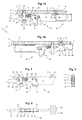
- Figures 1a and 1b illustrate, in elevational views, the body 1 of the present invention in a so-called open position on a plane tool 2 represented in chopped off. Being of elongated shape whose geometry is reminiscent of a bar, the representation of the organ 1 is illustrated in two portions, respectively in the Figures 1a and 1b.
- FIG. 1a shows the front portion 10 of the member 1 as well as its central portion 30 in partial section, while Figure 1b shows the rear portion 40 intended to fit into the central portion 30.
- the general form of the member 1 is preferably that of a rectilinear bar narrow profile, arranged on its upper edge 3 against the lower surface 4 of the plane tool 2. The latter typically being an ejection board of a non platinum press illustrated.
- the front part 10 comprises in particular a body 11 provided with a mechanism 20 which makes it possible to fix the member 1 on the plane tool 2 moving from a so-called open position to a so-called closed position, and vice versa remove it to separate it from the plan 2 tool.
- the attachment of the member 1 is effected by means of at least one fixed pin 12 and minus a movable pin 13, all integral with the member 1 and each intended to come engaged with a flank 5 of an opening 6 formed for this purpose in the plane tool 2.
- Each of these lugs has a sharp or pointed end that can be plant easily in wood for example.
- the fixed pin 12 is turned towards the rear and consists of an outgrowth of the body 11 located at the rear end of the latter, against the upper edge 3.
- the ergot mobile 13 is turned towards the front so that it points in the direction opposite to that of the fixed pin 12.
- the movable pin 13 can move in the longitudinal direction and constitutes the upper part of a stirrup 14 mounted in tilting about an axis 15 passing through the body 11 of the member 1, as illustrated particularly in Figure 3.
- the longitudinal movement of the movable pin 13 is obtained by the action of the mechanism 20 which, in the open position, brings the stirrup 14 back into an orientation preferably vertical as shown in Figure 1a, and in the closed position, as shown in Figure 2, the force to swing forward around its axis of rotation 15 so that the mobile pin 13 can come to grip the plane tool 2, by inserting into the flank 5 of the corresponding opening 6.
- the closing and opening mechanism 20 comprises a bent handle 21, acting as a lever, connected at one of its ends to a rod 23 by a first articulation 22 and connected at its heel to the end of a bar 24 by a second articulation 25.
- this bar 24 also serves as a lever and is supported at its opposite end to the bottom a light 16 formed in the body 11 of the member 1.
- the rod 23 crosses the stirrup 14 and slides longitudinally in an embrasure 17 made in this manner. effect in the body 11 of the organ 1.
- This rod 23 comprises, between the first 22 articulation and the stirrup 14, a scope around which takes place a means elastic 27, illustrated in Figures 1a, 2 and 4 by a compression spring.
- This elastic means, or compression spring is supported at the rear against a shoulder 28 of the rod 23, and at the front against the stirrup 14 pushing the latter until abutting against a locking pin 29 fixed transversely to the 23.
- the movable pin 13 is thus pushed both by the action of the handle bent 21, when it is closed, and by the action of the elastic means 27.
- At least one fin 18 is reported therein for the purpose of constituting a small additional support surface leaning against the lower surface 4 of the plan tool 2.
- the organ 1 can be apprehended by the device of marking and clamping, not shown but provided in the platen press for correctly maintain the plane tool 2 in the machine, at least one end 19 of this member 1 is profiled accordingly.
- FIG. 1b illustrates the rear part 40 of the organ 1 of the present invention.
- This rear part detachable from the rest of the organ 1 without this in a necessity, is movable in the longitudinal direction with respect to the before 10, preferably by sliding.
- it is composed in particular a sliding portion 41 and a tail 42.
- the sliding portion 41 slides along the central portion 30 of the organ 1.
- the central portion 30 is a tubular portion whose interior dimensions are slightly greater than the outer dimensions of the sliding portion 41.
- the tail 42 is provided with a lug 43 turned towards the front and shaped similar or identical to that of the fixed pin 12 described above.
- the ergot 43 is preferably fixed and its function is also identical to that of the fixed lug 12.
- the tail is also provided with a fin 18 for stabilizing the 1.
- this tail is also provided with a fastening mechanism 20 identical to that previously described in the front part 10.
- the rear part 40 of the body of the present invention comprises a bumper 45 against which can be supported a clamping member, specific to the machine packing, pushing the rear portion 40 in the longitudinal direction.
- a crossbar of this machine comes to slide on a flat 44 arranged to the end of the tail 42, on the lower edge 7 of the organ 1.
- This bar no illustrated as being part of a fastener external to the present invention, is the clamping member that keeps the plane tool 2 in the machine.
- this crossbar will therefore push the tail 42 of the body 1 to the front, so that the lug 43 crashes into the flank 5 of the opening 6 corresponding and thus drives all the plane tool 2 in the same direction until it can be apprehended in the machine by the end 19.
- the use of the organ 1 of the present invention has the advantage of being simple, fast and reliable.
- To set up and fix this organ simply insert the pins 12, 13 of the front portion 10 in the corresponding openings 6 of the plane tool 2, to adjust the length of the member 1 by sliding the rear portion 40 along the central portion 30 until the lug 43 of the tail 42 also slides in an opening 6, to press the upper edge 3 of the member 1 against the lower surface 4 of the planar tool, and lower the bent handle 21 in order to close the fastening mechanism.
- the reverse sequence of these operations allows remove the organ just as easily from its plane tool.
- placement and removal of the organ 1 does not require any additional tools, nor no other mechanical parts.
- the joints 22, 25, the axis 15 and the locking pin 29 can for example be made by means of simple elastic pins.
- the cutting shapes of the front 10 and rear 40 parts may for example be advantageously laser-machined, just like the light 16 and the embrasure 17 especially.
- the tubular shape of the central portion 30 can be obtained by folding and welding a plate provided for this purpose.
- the assembly of the front and central, as the assembly of the fins 18, can also be realized simply by welding. As a result, it will be noted that the cost of producing a reinforcement body can be reduced to a minimum without the strength it requires.
- the openings 6 are preferably of square shape or rectangular and that their flanks are advantageously vertical but could be slightly inclined or have a particular profile. Machining openings 6 can be done very easily by means of a laser, especially when the Planar tools are made of wood as is usually the case. This mode machining makes it possible to obtain a clean and precise cut while respecting tolerances sufficient for such an application. Moreover, thanks to the action of the elastic means 27 of the fastening mechanism, the member 1 is undoubtedly fixed without play in the plane tool 2. Advantageously, the openings 6 do not require therefore no close tolerances, which advantageously contributes to reduce manufacturing costs.
- the lugs 12, 13, 43 are advantageously all embedded in the thickness e of the plane tool 2 and do not stand out therefore not on the upper surface 8 of the plane tool 2.
- This preferred arrangement avoids any presence of projections on the upper surface 8 of the planar tool, and this fact eliminates any risk of snagging with machine parts in movement in the platen press as the bars of scrolling pliers precisely along this upper surface.
- such an arrangement also avoids any risk of injury to the machinist who must manipulate such flat tools, especially during operations such as changes of these tools during the preparation of the machine.
- the mechanism 20 of the front portion 10 is preferentially reproduced in the rear part 40 of organ 1, it is not impossible to arrange this mechanism only in the front part or in the back part of the member 1, or at another location along the member 1.
- organ 1 are preferentially made of metal, such as steel or aluminum, without this it is a necessity.
- the profile general of the organ 1 is of rectangular section and its thickness depends essentially the stiffness of the material used, the maximum length that can have the organ 1, as well as the effort that must be taken up by the tool plane 2 in order to can at least withstand the strongest constraint for which he has been dimensioned.
Landscapes
- Life Sciences & Earth Sciences (AREA)
- Forests & Forestry (AREA)
- Engineering & Computer Science (AREA)
- Mechanical Engineering (AREA)
- Portable Nailing Machines And Staplers (AREA)
- Making Paper Articles (AREA)
- Auxiliary Devices For And Details Of Packaging Control (AREA)
- Perforating, Stamping-Out Or Severing By Means Other Than Cutting (AREA)
Priority Applications (3)
| Application Number | Priority Date | Filing Date | Title |
|---|---|---|---|
| EP04405056A EP1559521B1 (de) | 2004-01-30 | 2004-01-30 | Verstärkungselement für flache Werkzeuge in einer Machine für die Verpackungsindustrie |
| AT04405056T ATE358560T1 (de) | 2004-01-30 | 2004-01-30 | Verstärkungselement für flache werkzeuge in einer machine für die verpackungsindustrie |
| DE602004005659T DE602004005659T2 (de) | 2004-01-30 | 2004-01-30 | Verstärkungselement für flache Werkzeuge in einer Maschine für die Verpackungsindustrie |
Applications Claiming Priority (1)
| Application Number | Priority Date | Filing Date | Title |
|---|---|---|---|
| EP04405056A EP1559521B1 (de) | 2004-01-30 | 2004-01-30 | Verstärkungselement für flache Werkzeuge in einer Machine für die Verpackungsindustrie |
Publications (2)
| Publication Number | Publication Date |
|---|---|
| EP1559521A1 true EP1559521A1 (de) | 2005-08-03 |
| EP1559521B1 EP1559521B1 (de) | 2007-04-04 |
Family
ID=34639503
Family Applications (1)
| Application Number | Title | Priority Date | Filing Date |
|---|---|---|---|
| EP04405056A Expired - Lifetime EP1559521B1 (de) | 2004-01-30 | 2004-01-30 | Verstärkungselement für flache Werkzeuge in einer Machine für die Verpackungsindustrie |
Country Status (3)
| Country | Link |
|---|---|
| EP (1) | EP1559521B1 (de) |
| AT (1) | ATE358560T1 (de) |
| DE (1) | DE602004005659T2 (de) |
Families Citing this family (1)
| Publication number | Priority date | Publication date | Assignee | Title |
|---|---|---|---|---|
| CN120303091A (zh) | 2022-12-02 | 2025-07-11 | 鲍勃斯脱梅克斯股份有限公司 | 支撑装置和纸板加工机 |
Citations (4)
| Publication number | Priority date | Publication date | Assignee | Title |
|---|---|---|---|---|
| GB469122A (en) * | 1936-01-25 | 1937-07-20 | Hoe & Co R | Improvements in or relating to type forms or chases |
| GB857265A (en) * | 1957-02-05 | 1960-12-29 | William Frank Golding | Holder for sheet material working tools |
| GB2337224A (en) * | 1998-04-16 | 1999-11-17 | Ralegh Limited | Die cutting apparatus |
| US20030211925A1 (en) * | 2002-03-28 | 2003-11-13 | Bobst S.A. | Supporting, fastening and reinforcing member for a plane tool used in a waste stripping station of a diecutting press |
-
2004
- 2004-01-30 EP EP04405056A patent/EP1559521B1/de not_active Expired - Lifetime
- 2004-01-30 DE DE602004005659T patent/DE602004005659T2/de not_active Expired - Lifetime
- 2004-01-30 AT AT04405056T patent/ATE358560T1/de not_active IP Right Cessation
Patent Citations (4)
| Publication number | Priority date | Publication date | Assignee | Title |
|---|---|---|---|---|
| GB469122A (en) * | 1936-01-25 | 1937-07-20 | Hoe & Co R | Improvements in or relating to type forms or chases |
| GB857265A (en) * | 1957-02-05 | 1960-12-29 | William Frank Golding | Holder for sheet material working tools |
| GB2337224A (en) * | 1998-04-16 | 1999-11-17 | Ralegh Limited | Die cutting apparatus |
| US20030211925A1 (en) * | 2002-03-28 | 2003-11-13 | Bobst S.A. | Supporting, fastening and reinforcing member for a plane tool used in a waste stripping station of a diecutting press |
Also Published As
| Publication number | Publication date |
|---|---|
| EP1559521B1 (de) | 2007-04-04 |
| DE602004005659T2 (de) | 2007-12-13 |
| ATE358560T1 (de) | 2007-04-15 |
| DE602004005659D1 (de) | 2007-05-16 |
Similar Documents
| Publication | Publication Date | Title |
|---|---|---|
| EP1273399B1 (de) | Schneidvorrichtung mit zurückziehbarer Klinge | |
| EP0555709B1 (de) | Tragrahmen zum zeitweiligen Abstützen von horizontalen Scheiben während des Stapelns | |
| FR2608958A3 (fr) | Dispositif de papeterie portatif en particulier agrafeuse et poinconneuse combinees | |
| EP1250988B1 (de) | Vorrichtung zur Montage und Demontage der Tücher einer Gegenwalze in einer Rotationsstanzmaschine | |
| EP1559521B1 (de) | Verstärkungselement für flache Werkzeuge in einer Machine für die Verpackungsindustrie | |
| EP1348524B1 (de) | Vorrichtung zum Stützen, Fixieren und Verstärken eines ebenen Werkzeuges in einer Station zum Auswerfen von Abfall aus einer Stanzpresse | |
| FR3020581A1 (fr) | Procede et dispositif pour eliminer des morceaux predecoupes d'une feuille de matiere ainsi qu'un organe d'ejection pour un tel dispositif | |
| FR2671300A1 (fr) | Procede de pose d'une agrafe repliee sur des longueurs superposees de feuillard et ensemble d'agrafage. | |
| EP2181840B1 (de) | Abviervorrichtung für eine Formlinie von Verpackungen | |
| EP1357816A1 (de) | Kombinierte werkzeuge zum ansenken und einführen von stiften | |
| EP2077932A1 (de) | Schneidwerkzeug zum segmentieren von festen langen elementen | |
| EP2205386B1 (de) | Schneidwerkzeug zum trennen von offenen profilen | |
| EP1985422B1 (de) | Papierlocher mit Zentriervorrichtung | |
| EP3820265A1 (de) | Verfahren und vorrichtung zum schneiden eines radialen elektronischen bauteils | |
| EP1524221B1 (de) | Ausbrechstation einer Stanzpresse | |
| EP3363282B1 (de) | Vorrichtung zur regulierung der öffnung einer tasche oder zur bildung einer tasche und zur regulierung der öffnung dieser tasche | |
| EP0421114B1 (de) | Befestigung eines Werkzeugs zum Ausstossen oder Abtrennen von Teilen oder eines ähnlichen Werkzeugs | |
| EP0764501A1 (de) | Rahmen mit Schnellspanneinrichtung für Stanzwerkzeuge | |
| EP2391503B1 (de) | Vorrichtung und verfahren zur anordnung eines schiebers auf einem beutel mit verschlussprofilen | |
| FR2882284A1 (fr) | Mecanisme pour le verrouillage d'un outil de racloir | |
| FR2717109A1 (fr) | Dispositif de pliage d'une tôle le long d'une ligne droite. | |
| JP2005212482A (ja) | 特にパッケージング工業用機械に使用するフラットツールの補強装置 | |
| EP1266727A1 (de) | Dynamischer Auswerfer für Ausbrechteile in einer Maschine zum Schneiden von bogenförmigen Materialien | |
| BE901271A (fr) | Pince de guidage. | |
| FR2597795A1 (fr) | Tete de piquage utilisee pour le brochage a plat de piles de papier au moyen d'une agrafe en u, comportant un dispositif de separation des agrafes et un pousseur distincts |
Legal Events
| Date | Code | Title | Description |
|---|---|---|---|
| PUAI | Public reference made under article 153(3) epc to a published international application that has entered the european phase |
Free format text: ORIGINAL CODE: 0009012 |
|
| AK | Designated contracting states |
Kind code of ref document: A1 Designated state(s): AT BE BG CH CY CZ DE DK EE ES FI FR GB GR HU IE IT LI LU MC NL PT RO SE SI SK TR |
|
| AX | Request for extension of the european patent |
Extension state: AL LT LV MK |
|
| 17P | Request for examination filed |
Effective date: 20050909 |
|
| AKX | Designation fees paid |
Designated state(s): AT BE BG CH CY CZ DE DK EE ES FI FR GB GR HU IE IT LI LU MC NL PT RO SE SI SK TR |
|
| GRAP | Despatch of communication of intention to grant a patent |
Free format text: ORIGINAL CODE: EPIDOSNIGR1 |
|
| GRAS | Grant fee paid |
Free format text: ORIGINAL CODE: EPIDOSNIGR3 |
|
| GRAA | (expected) grant |
Free format text: ORIGINAL CODE: 0009210 |
|
| AK | Designated contracting states |
Kind code of ref document: B1 Designated state(s): AT BE BG CH CY CZ DE DK EE ES FI FR GB GR HU IE IT LI LU MC NL PT RO SE SI SK TR |
|
| PG25 | Lapsed in a contracting state [announced via postgrant information from national office to epo] |
Ref country code: SI Free format text: LAPSE BECAUSE OF FAILURE TO SUBMIT A TRANSLATION OF THE DESCRIPTION OR TO PAY THE FEE WITHIN THE PRESCRIBED TIME-LIMIT Effective date: 20070404 Ref country code: FI Free format text: LAPSE BECAUSE OF FAILURE TO SUBMIT A TRANSLATION OF THE DESCRIPTION OR TO PAY THE FEE WITHIN THE PRESCRIBED TIME-LIMIT Effective date: 20070404 |
|
| REG | Reference to a national code |
Ref country code: GB Ref legal event code: FG4D Free format text: NOT ENGLISH |
|
| REG | Reference to a national code |
Ref country code: CH Ref legal event code: EP |
|
| REF | Corresponds to: |
Ref document number: 602004005659 Country of ref document: DE Date of ref document: 20070516 Kind code of ref document: P |
|
| REG | Reference to a national code |
Ref country code: IE Ref legal event code: FG4D Free format text: LANGUAGE OF EP DOCUMENT: FRENCH |
|
| PG25 | Lapsed in a contracting state [announced via postgrant information from national office to epo] |
Ref country code: SE Free format text: LAPSE BECAUSE OF FAILURE TO SUBMIT A TRANSLATION OF THE DESCRIPTION OR TO PAY THE FEE WITHIN THE PRESCRIBED TIME-LIMIT Effective date: 20070704 |
|
| PG25 | Lapsed in a contracting state [announced via postgrant information from national office to epo] |
Ref country code: ES Free format text: LAPSE BECAUSE OF FAILURE TO SUBMIT A TRANSLATION OF THE DESCRIPTION OR TO PAY THE FEE WITHIN THE PRESCRIBED TIME-LIMIT Effective date: 20070715 |
|
| GBT | Gb: translation of ep patent filed (gb section 77(6)(a)/1977) |
Effective date: 20070628 |
|
| PG25 | Lapsed in a contracting state [announced via postgrant information from national office to epo] |
Ref country code: PT Free format text: LAPSE BECAUSE OF FAILURE TO SUBMIT A TRANSLATION OF THE DESCRIPTION OR TO PAY THE FEE WITHIN THE PRESCRIBED TIME-LIMIT Effective date: 20070904 |
|
| NLV1 | Nl: lapsed or annulled due to failure to fulfill the requirements of art. 29p and 29m of the patents act | ||
| PG25 | Lapsed in a contracting state [announced via postgrant information from national office to epo] |
Ref country code: AT Free format text: LAPSE BECAUSE OF FAILURE TO SUBMIT A TRANSLATION OF THE DESCRIPTION OR TO PAY THE FEE WITHIN THE PRESCRIBED TIME-LIMIT Effective date: 20070404 |
|
| REG | Reference to a national code |
Ref country code: IE Ref legal event code: FD4D |
|
| PG25 | Lapsed in a contracting state [announced via postgrant information from national office to epo] |
Ref country code: BG Free format text: LAPSE BECAUSE OF FAILURE TO SUBMIT A TRANSLATION OF THE DESCRIPTION OR TO PAY THE FEE WITHIN THE PRESCRIBED TIME-LIMIT Effective date: 20070704 Ref country code: NL Free format text: LAPSE BECAUSE OF FAILURE TO SUBMIT A TRANSLATION OF THE DESCRIPTION OR TO PAY THE FEE WITHIN THE PRESCRIBED TIME-LIMIT Effective date: 20070404 Ref country code: CZ Free format text: LAPSE BECAUSE OF FAILURE TO SUBMIT A TRANSLATION OF THE DESCRIPTION OR TO PAY THE FEE WITHIN THE PRESCRIBED TIME-LIMIT Effective date: 20070404 Ref country code: DK Free format text: LAPSE BECAUSE OF FAILURE TO SUBMIT A TRANSLATION OF THE DESCRIPTION OR TO PAY THE FEE WITHIN THE PRESCRIBED TIME-LIMIT Effective date: 20070404 Ref country code: IE Free format text: LAPSE BECAUSE OF FAILURE TO SUBMIT A TRANSLATION OF THE DESCRIPTION OR TO PAY THE FEE WITHIN THE PRESCRIBED TIME-LIMIT Effective date: 20070404 |
|
| PLBE | No opposition filed within time limit |
Free format text: ORIGINAL CODE: 0009261 |
|
| STAA | Information on the status of an ep patent application or granted ep patent |
Free format text: STATUS: NO OPPOSITION FILED WITHIN TIME LIMIT |
|
| PG25 | Lapsed in a contracting state [announced via postgrant information from national office to epo] |
Ref country code: SK Free format text: LAPSE BECAUSE OF FAILURE TO SUBMIT A TRANSLATION OF THE DESCRIPTION OR TO PAY THE FEE WITHIN THE PRESCRIBED TIME-LIMIT Effective date: 20070404 |
|
| 26N | No opposition filed |
Effective date: 20080107 |
|
| PG25 | Lapsed in a contracting state [announced via postgrant information from national office to epo] |
Ref country code: IT Free format text: LAPSE BECAUSE OF FAILURE TO SUBMIT A TRANSLATION OF THE DESCRIPTION OR TO PAY THE FEE WITHIN THE PRESCRIBED TIME-LIMIT Effective date: 20070404 Ref country code: GR Free format text: LAPSE BECAUSE OF FAILURE TO SUBMIT A TRANSLATION OF THE DESCRIPTION OR TO PAY THE FEE WITHIN THE PRESCRIBED TIME-LIMIT Effective date: 20070705 |
|
| PG25 | Lapsed in a contracting state [announced via postgrant information from national office to epo] |
Ref country code: RO Free format text: LAPSE BECAUSE OF FAILURE TO SUBMIT A TRANSLATION OF THE DESCRIPTION OR TO PAY THE FEE WITHIN THE PRESCRIBED TIME-LIMIT Effective date: 20070404 |
|
| BERE | Be: lapsed |
Owner name: BOBST S.A. Effective date: 20080131 |
|
| PG25 | Lapsed in a contracting state [announced via postgrant information from national office to epo] |
Ref country code: MC Free format text: LAPSE BECAUSE OF NON-PAYMENT OF DUE FEES Effective date: 20080131 |
|
| PG25 | Lapsed in a contracting state [announced via postgrant information from national office to epo] |
Ref country code: EE Free format text: LAPSE BECAUSE OF FAILURE TO SUBMIT A TRANSLATION OF THE DESCRIPTION OR TO PAY THE FEE WITHIN THE PRESCRIBED TIME-LIMIT Effective date: 20070404 |
|
| PG25 | Lapsed in a contracting state [announced via postgrant information from national office to epo] |
Ref country code: BE Free format text: LAPSE BECAUSE OF NON-PAYMENT OF DUE FEES Effective date: 20080131 |
|
| PG25 | Lapsed in a contracting state [announced via postgrant information from national office to epo] |
Ref country code: CY Free format text: LAPSE BECAUSE OF FAILURE TO SUBMIT A TRANSLATION OF THE DESCRIPTION OR TO PAY THE FEE WITHIN THE PRESCRIBED TIME-LIMIT Effective date: 20070404 |
|
| PG25 | Lapsed in a contracting state [announced via postgrant information from national office to epo] |
Ref country code: LU Free format text: LAPSE BECAUSE OF NON-PAYMENT OF DUE FEES Effective date: 20080130 Ref country code: HU Free format text: LAPSE BECAUSE OF FAILURE TO SUBMIT A TRANSLATION OF THE DESCRIPTION OR TO PAY THE FEE WITHIN THE PRESCRIBED TIME-LIMIT Effective date: 20071005 |
|
| PG25 | Lapsed in a contracting state [announced via postgrant information from national office to epo] |
Ref country code: TR Free format text: LAPSE BECAUSE OF FAILURE TO SUBMIT A TRANSLATION OF THE DESCRIPTION OR TO PAY THE FEE WITHIN THE PRESCRIBED TIME-LIMIT Effective date: 20070404 |
|
| PGFP | Annual fee paid to national office [announced via postgrant information from national office to epo] |
Ref country code: GB Payment date: 20130130 Year of fee payment: 10 Ref country code: DE Payment date: 20130123 Year of fee payment: 10 Ref country code: CH Payment date: 20130108 Year of fee payment: 10 Ref country code: FR Payment date: 20130215 Year of fee payment: 10 |
|
| REG | Reference to a national code |
Ref country code: DE Ref legal event code: R119 Ref document number: 602004005659 Country of ref document: DE |
|
| REG | Reference to a national code |
Ref country code: CH Ref legal event code: PL |
|
| GBPC | Gb: european patent ceased through non-payment of renewal fee |
Effective date: 20140130 |
|
| PG25 | Lapsed in a contracting state [announced via postgrant information from national office to epo] |
Ref country code: CH Free format text: LAPSE BECAUSE OF NON-PAYMENT OF DUE FEES Effective date: 20140131 Ref country code: LI Free format text: LAPSE BECAUSE OF NON-PAYMENT OF DUE FEES Effective date: 20140131 Ref country code: DE Free format text: LAPSE BECAUSE OF NON-PAYMENT OF DUE FEES Effective date: 20140801 |
|
| REG | Reference to a national code |
Ref country code: FR Ref legal event code: ST Effective date: 20140930 |
|
| REG | Reference to a national code |
Ref country code: DE Ref legal event code: R119 Ref document number: 602004005659 Country of ref document: DE Effective date: 20140801 |
|
| PG25 | Lapsed in a contracting state [announced via postgrant information from national office to epo] |
Ref country code: FR Free format text: LAPSE BECAUSE OF NON-PAYMENT OF DUE FEES Effective date: 20140131 Ref country code: GB Free format text: LAPSE BECAUSE OF NON-PAYMENT OF DUE FEES Effective date: 20140130 |