EP1559559A2 - Ink cartridge - Google Patents
Ink cartridge Download PDFInfo
- Publication number
- EP1559559A2 EP1559559A2 EP05001789A EP05001789A EP1559559A2 EP 1559559 A2 EP1559559 A2 EP 1559559A2 EP 05001789 A EP05001789 A EP 05001789A EP 05001789 A EP05001789 A EP 05001789A EP 1559559 A2 EP1559559 A2 EP 1559559A2
- Authority
- EP
- European Patent Office
- Prior art keywords
- ink cartridge
- locking
- housing
- cartridge according
- ventilation
- Prior art date
- Legal status (The legal status is an assumption and is not a legal conclusion. Google has not performed a legal analysis and makes no representation as to the accuracy of the status listed.)
- Granted
Links
- 238000009423 ventilation Methods 0.000 claims abstract description 97
- 230000004913 activation Effects 0.000 claims abstract description 11
- 239000011888 foil Substances 0.000 claims description 8
- 238000004891 communication Methods 0.000 claims description 7
- 238000003780 insertion Methods 0.000 claims description 6
- 230000037431 insertion Effects 0.000 claims description 6
- 239000012530 fluid Substances 0.000 claims description 5
- 238000005273 aeration Methods 0.000 claims description 4
- 230000003213 activating effect Effects 0.000 abstract description 7
- 230000003993 interaction Effects 0.000 abstract 1
- 238000005452 bending Methods 0.000 description 11
- 238000004519 manufacturing process Methods 0.000 description 8
- 239000004033 plastic Substances 0.000 description 8
- 230000008901 benefit Effects 0.000 description 7
- 238000011161 development Methods 0.000 description 5
- 230000018109 developmental process Effects 0.000 description 5
- 238000012986 modification Methods 0.000 description 5
- 230000004048 modification Effects 0.000 description 5
- 230000006835 compression Effects 0.000 description 3
- 238000007906 compression Methods 0.000 description 3
- 238000013461 design Methods 0.000 description 3
- 238000000034 method Methods 0.000 description 3
- 238000004806 packaging method and process Methods 0.000 description 3
- 230000008569 process Effects 0.000 description 3
- 239000004743 Polypropylene Substances 0.000 description 2
- 230000015572 biosynthetic process Effects 0.000 description 2
- 238000001746 injection moulding Methods 0.000 description 2
- 239000010410 layer Substances 0.000 description 2
- -1 polypropylene Polymers 0.000 description 2
- 229920001155 polypropylene Polymers 0.000 description 2
- 238000007789 sealing Methods 0.000 description 2
- 238000012549 training Methods 0.000 description 2
- 230000009471 action Effects 0.000 description 1
- 239000002313 adhesive film Substances 0.000 description 1
- 239000012790 adhesive layer Substances 0.000 description 1
- 238000005276 aerator Methods 0.000 description 1
- 238000010276 construction Methods 0.000 description 1
- 230000008878 coupling Effects 0.000 description 1
- 238000010168 coupling process Methods 0.000 description 1
- 238000005859 coupling reaction Methods 0.000 description 1
- 230000001419 dependent effect Effects 0.000 description 1
- 238000002347 injection Methods 0.000 description 1
- 239000007924 injection Substances 0.000 description 1
- 239000007788 liquid Substances 0.000 description 1
- 239000000463 material Substances 0.000 description 1
- 238000007639 printing Methods 0.000 description 1
- 230000007704 transition Effects 0.000 description 1
- 238000013022 venting Methods 0.000 description 1
Images



Classifications
-
- B—PERFORMING OPERATIONS; TRANSPORTING
- B41—PRINTING; LINING MACHINES; TYPEWRITERS; STAMPS
- B41J—TYPEWRITERS; SELECTIVE PRINTING MECHANISMS, i.e. MECHANISMS PRINTING OTHERWISE THAN FROM A FORME; CORRECTION OF TYPOGRAPHICAL ERRORS
- B41J2/00—Typewriters or selective printing mechanisms characterised by the printing or marking process for which they are designed
- B41J2/005—Typewriters or selective printing mechanisms characterised by the printing or marking process for which they are designed characterised by bringing liquid or particles selectively into contact with a printing material
- B41J2/01—Ink jet
- B41J2/17—Ink jet characterised by ink handling
- B41J2/175—Ink supply systems ; Circuit parts therefor
- B41J2/17503—Ink cartridges
- B41J2/1752—Mounting within the printer
-
- B—PERFORMING OPERATIONS; TRANSPORTING
- B41—PRINTING; LINING MACHINES; TYPEWRITERS; STAMPS
- B41J—TYPEWRITERS; SELECTIVE PRINTING MECHANISMS, i.e. MECHANISMS PRINTING OTHERWISE THAN FROM A FORME; CORRECTION OF TYPOGRAPHICAL ERRORS
- B41J2/00—Typewriters or selective printing mechanisms characterised by the printing or marking process for which they are designed
- B41J2/005—Typewriters or selective printing mechanisms characterised by the printing or marking process for which they are designed characterised by bringing liquid or particles selectively into contact with a printing material
- B41J2/01—Ink jet
- B41J2/17—Ink jet characterised by ink handling
- B41J2/175—Ink supply systems ; Circuit parts therefor
- B41J2/17503—Ink cartridges
- B41J2/17556—Means for regulating the pressure in the cartridge
Definitions
- the invention relates to an ink cartridge according to the preamble of claim 1 for Insertion in a cartridge receptacle of an inkjet printer, by a locking device can be locked in the cartridge holder.
- Lockable ink cartridges of the type mentioned in which a pressure equalization with the environment through an integrated in the ink cartridge ventilation takes place, are known from the prior art. With the help of the ventilation device should to be achieved that the discharge of the ink stored in the ink storage chamber evenly and without interruptions during the printing process takes place and preferably all of the ink contained in the ink storage chamber from the ink cartridge is delivered.
- the ventilation device only immediately before using the ink cartridge.
- a disadvantage of this known ink cartridge is that the activation of the ventilation device - and thus the proper functioning of the ink cartridge - of the proper Removing the slide depends.
- the film to be withdrawn to connect with the packaging of the ink cartridge so that the film when opening the Packaging for activating the ventilation device is removed with.
- EP 0 685 340 A1, EP 0 792 749 A2 and JP 11268290 each disclose an ink cartridge in which the package of the ink cartridge so with the deducted Foil of the ventilation device is connected to that at a proper Opening the package at the same time removes the film to be removed from the ink cartridge and thus the aeration device is activated.
- the disadvantage here is that the film only then properly removed, although the packaging according to the Specifications of the manufacturer is opened.
- an actuator provide, in the locking position of the locking device with the Ventilation device is in operative connection.
- the locking device to couple with the ventilation device so that the ventilation device already during the movement of the locking device into its locking position the ventilation device activates the ventilation device in the final locking position however, the locking device no longer with the locking device is in operative connection, but independently in their ventilation position holds.
- Ink cartridge has the aeration device to be opened for their activation Ventilation opening on.
- the locking device equipped with an actuator that at least during the Movement of the locking device in its locking position in the ventilation opening is at least partially introduced to open this.
- the ventilation opening before the first use of Ink cartridge closed by a foil Activating the ventilation device then takes place by serving as an actuator actuating mandrel, which at the movement of the locking device in its locking position for opening the ventilation opening pierces the film.
- the thus designed ink cartridge according to the invention is comparatively easy to manufacture.
- the foil closing the ventilation opening is preferred in this development glued or sealed to the housing.
- Under sealing is in this context either understood the use of a multilayer film whose with the Housing to be connected side is provided with a fusible plastic layer, which is fused with the housing.
- the film is made by a meltable Adhesive layer connected to the housing.
- the ventilation opening in the manufacture of the usually made of plastic, for example polypropylene, manufactured housing by a molded or molded thin plastic skin or plastic layer to close, which serves as a film to be pierced.
- the ventilation opening of the ventilation device closed by a valve arrangement.
- a ball valve used that due to its relatively simple construction with low Effort is to produce and at the same time a fluid-tight sealing of the ventilation opening guaranteed.
- the actuating element of the locking device activates the Ventilation device in which the actuating element during the movement of the locking device in its locking position with a valve element of the valve arrangement, which between a ventilation opening closing position and a the vent releasing position is movable, engages and this moved to its opening position to open the ventilation opening.
- the ventilation device in a particularly preferred embodiment of the invention Ink cartridge with one in fluid communication with the vent standing channel, which through an opening with the housing interior in Flow connection is.
- the channel serves as a buffer of possibly ink escaping from the ink cartridge, allowing for immediate leakage of ink is prevented from the ink storage chamber with activated ventilation device.
- the channel preferably meandering.
- the ventilation opening is in this case preferably formed in an upper portion of the compensation chamber, so that the compensation chamber must first be completely filled with ink until ink from the open ventilation opening can escape.
- the channel is on a flat side of the housing, preferably the top of the housing, formed while the Compensation chamber at one to the channeled flat side of the housing adjacent further flat side of the housing is provided, in which the ventilation opening immediately flows.
- Channel and / or the compensation chamber formed directly on the housing, wherein the Channel and / or the compensation chamber to the outside at least partially open are or is. Then the open channel and the open compensation chamber through one on the housing glued or sealed foil closed to the outside.
- a Locking lever as a locking device pivotally mounted on the housing Ink cartridge is stored.
- the formation of a pivotable locking lever than Locking device has the advantage that the pivoting movement of the locking lever when locking the ink cartridge in the cartridge holder without much effort can also be used to activate the ventilation device in which the activating element of the ventilation device, for example the film or the valve element the previously described valve assembly, in the pivoting range of the locking lever is arranged.
- the ventilation device in a very simple and elegant way when locking the ink cartridge in the cartridge receptacle are activated.
- the locking lever is preferably mounted by a film hinge on the housing.
- a film hinge is on the one hand very easy to manufacture, since such film hinges easy to train in plastic injection molding and without too much effort are demoulding.
- On the other hand accounts for additional assembly steps, in training of the locking lever are required as a separate component to the locking lever at a correspondingly formed on the housing bearing pivotally Fasten. In certain cases, such as a complex shape of the locking lever, However, it may well be useful to the locking lever as form a separate component.
- the locking lever is designed to be in its first phase around its Swivel axis from a rest position to an intermediate position, in which he with a it formed support surface on the outside of the housing comes to rest, to is pivoting, and in a second phase, in which the locking lever with his Supporting surface supported on the housing, starting from the intermediate position in the direction of Swivel axis is to bend elastically in its locking position.
- the locking lever in a plane perpendicular to the housing surface level can be bent in its second phase of movement, lies the support surface, with the the locking lever on the outside of the housing comes to rest, in a parallel to the Pivot axis of the locking lever extending plane.
- the bending direction of the Locking lever can be specified in a desired bending direction.
- the support surface so that it lies in a plane which at an angle in a range of about 30 to 60 °, preferably in a range from about 40 to 50 ° inclined to the flat side of the locking lever extends. Since the Locking lever only then elastically deformed when the support surface on the outside the entire surface of the housing, can by defined predetermining the inclination angle the support surface to be adjusted the force with which the locking lever after the Lock with the cartridge holder is elastically biased.
- a grid lift for example in shape on the locking lever a latching nose, is formed, which with inserted ink cartridge with a on the Cartridge receptacle provided latching edge for locking the ink cartridge into engagement can be brought.
- the locking edge can be designed so that the locking edge during insertion the ink cartridge comes into operative connection with the locking lever and this moved by the insertion movement into its locking position, at the same time the Ventilation device is activated.
- the upper side 20 of the housing 12 is closed by a cover 22.
- a dashed opening 24 is formed, which with a formed in the housing 12 ink storage chamber 26 (see Fig. 2 to 6) in flow communication in which a porous ink reservoir 28 for storing liquid ink is included.
- the opening 24 is in a partially meandering running Channel 30 (also shown in dashed lines) in flow communication, which on the lid 22 of the housing 12 is excluded.
- the channel 30 terminates in a connection opening 32 smaller diameter near the other side surface 34 of the housing 12th
- a compensation chamber 36 is formed, which, as shown for example in Fig. 2, at her upper end open and closed by the lid 22.
- the connection opening 32 on the cover 22 is formed on the lid 22 so that it with the compensation chamber 36 is in fluid communication.
- the compensation chamber 36 opens at the Side surface 34 formed ventilation opening 38th
- the opening 24, the channel 30, the connection opening 32 and the ventilation opening 38 which are open to the outside and covered by a common film 40, which is glued fluid-tight with the housing 12 or sealed onto this form together with the compensation chamber 38, a ventilation device 42 for venting the Ink storage chamber 26.
- a locking device 44 On the side surface 34 of the housing 12 is a locking device 44 in the form a locking lever 46 is provided, whose structure is described below with reference 2 is described in more detail.
- the locking lever 46 by a film hinge 48 at hinged to the outside of the housing 12 and extending transversely to the side surface 34 Swivel axis A (see Fig. 1) pivotally.
- the locking lever 46 has a Bending section 50, the operation will be explained later in detail, at the free end a parallel to the pivot axis A extending grid elevation 52 formed is.
- a release lever 54 is formed near the grid elevation 52.
- an actuating mandrel 56 is formed, which is about perpendicular from the front of the locking lever 46 rises and three pointed tapered, triangular surface elements 58 is composed, which on the Locking lever 46 are integrally formed.
- the bending portion 50 forms a right angle to the film hinge 48 extending edge 60, which merges into a support surface 62.
- the Support surface 62 is located in a parallel to the pivot axis A extending plane and extends at an angle ⁇ of about 45 ° inclined to that shown in Fig. 2 above Front of the bending section 50
- the ink cartridge 10 is in a vertical movement in the cartridge receptacle 64th used, as indicated by the arrow to the connecting piece 14 with the To couple connection (not shown) of the printer in a known manner, the on the connecting piece 14 provided film from one at the terminal of the inkjet printer piercing pin is pierced.
- the lock lever 46 comes in the insertion movement of the ink cartridge 10 with an edge 66 on the cartridge receptacle 64 in contact, through which the Locking lever 46 is pressed in the direction of the side surface 34 of the housing 12.
- the locking lever 46 in a first phase on the film hinge 48 to the Swivel axis A pivoted so far until the support surface 62 with the side surface 34 of the Housing 12 comes into contact. The completion of this first phase is shown in FIG.
- the locking lever 46 springs back slightly and comes with the as Locking edge serving edge 66 in engagement.
- the actuating mandrel 56 is again slightly withdrawn from the vent 38, the film 40 in her pierced and expanded position remains.
- air can through the Ventilation opening 36, the compensation chamber 36, the connection opening 32, the channel 30 and the opening 24 between the ink storage chamber 26 and the environment for a pressure equalization flow back and forth.
- the locking lever 46 must only with Help the trigger lever 54 briefly bent so in the direction of the ink cartridge 10 until the ratchet 52 on the locking lever 56 detaches from the edge 66. Subsequently, the ink cartridge 10 in the opposite direction again from the Cartridge receptacle 64 are removed. If there is still ink in the ink cartridge 10 is included, the user can the vent 38 and, where appropriate, the Connecting piece 14 by sticking a supplied with the ink cartridge 10, self-adhesive film to be closed again.
- the ink cartridge 10 has the advantage that the opening of the ventilation device 42 and the locking of the ink cartridge 10 by means of the locking device 44 coupled and runs in a predetermined defined order. So the opening of the vent opening 42 takes place immediately before the ink cartridge 10th is locked with the edge 66.
- This has the advantage that a pressure equalization of Ink storage chamber 26 takes place only when the connecting piece 14 of the Ink cartridge 10 in the last movement phase of its Ankoppelvorgang to the Connection of the inkjet printer is located, leaving no ink at the port of the inkjet printer can escape from the ink cartridge 10 over.
- FIGs. 5 and 6 variations of the ink cartridge 10 are shown, which are merely differ by the way in which the vent 38 before activating the Ventilation device 42 is closed.
- FIG. 5 shows a modification of the ink cartridge 10, wherein the ventilation opening 42nd instead of with the film 40 by a in the vent 38 in the manufacture of the Housing 12 injected plastic skin 70 is closed. Again, the plastic skin 70 pierced by the action of the actuating mandrel 56 and on this The ventilation device 42 is activated.
- the ventilation opening 38 is the 38th closed by a valve arrangement in the form of a ball valve 72.
- the ball valve 72 has for this purpose a valve ball 74, which by a in the compensation chamber 36th supporting compression spring 76 against the inner circumferential edge of the ventilation opening 38th is biased and closes this fluid-tight.
- the locking lever 46 is in its locking position in the above described manner, wherein the actuating element 78 with the valve ball 74th the ball valve 72 comes into contact and pushes them into the compensation chamber 36, whereby the ventilation opening 38 is opened.
- the actuator 78 is again out of the Ventilation 38 withdrawn, the valve ball 74 by the force of Compression spring 76 is moved back into its closed position, in which they the ventilation opening 38 closes fluid-tight.
- the locking lever 46 may be formed as a separate component, that is mounted on a corresponding bearing on the outside of the housing 12 is. It is also conceivable, the locking lever 46 mechanically with a ventilation opening 38 closing valve assembly, for example in the form of a Ventilation opening 38 closing slide to mechanically couple.
Landscapes
- Ink Jet (AREA)
Abstract
Description
Die Erfindung betrifft eine Tintenpatrone nach dem Oberbegriff des Anspruchs 1 zum
Einsetzen in eine Patronenaufnahme eines Tintenstrahldruckers, die durch eine Verriegelungseinrichtung
in der Patronenaufnahme verriegelbar ist.The invention relates to an ink cartridge according to the preamble of
Verriegelbare Tintenpatronen der eingangs genannten Art, bei denen ein Druckausgleich mit der Umgebung durch eine in die Tintenpatrone integrierte Belüftungseinrichtung erfolgt, sind aus dem Stand der Technik bekannt. Mit Hilfe der Belüftungseinrichtung soll erreicht werden, dass die Abgabe der in der Tintenspeicherkammer gespeicherten Tinte gleichmäßig und ohne Unterbrechungen während des Druckvorganges erfolgt und möglichst die gesamte in der Tintenspeicherkammer enthaltene Tinte aus der Tintenpatrone abgegeben wird.Lockable ink cartridges of the type mentioned, in which a pressure equalization with the environment through an integrated in the ink cartridge ventilation takes place, are known from the prior art. With the help of the ventilation device should to be achieved that the discharge of the ink stored in the ink storage chamber evenly and without interruptions during the printing process takes place and preferably all of the ink contained in the ink storage chamber from the ink cartridge is delivered.
Damit die Tinte vor dem ersten Gebrauch der Tintenpatrone in einem Drucker nicht aus der Tintenpatrone austreten kann, ist es üblich, die Belüftungseinrichtung erst unmittelbar vor der Benutzung der Tintenpatrone zu aktivieren.So that the ink does not go out before using the ink cartridge in a printer for the first time the ink cartridge can escape, it is common, the ventilation device only immediately before using the ink cartridge.
So ist es bekannt, eine an der Belüftungseinrichtung vorgesehene Belüftungsöffnung während des Transportes und der Lagerung der Tintenpatrone mit einer Folie verschlossen zu halten, die unmittelbar vor der Benutzung der Tintenpatrone zur Aktivierung der Belüftungseinrichtung entfernt wird. Eine Tintenpatrone mit einer derart zu aktivierenden Belüftungseinrichtung ist beispielsweise in der EP 0 803 365 B1 beschrieben.It is thus known to provide a ventilation opening provided on the ventilation device sealed during transport and storage of the ink cartridge with a foil to hold the immediately before the use of the ink cartridge to activate the Ventilation device is removed. An ink cartridge with one to be activated Ventilation device is described for example in EP 0 803 365 B1.
Nachteilig an dieser bekannten Tintenpatrone ist, dass die Aktivierung der Belüftungseinrichtung - und damit die einwandfreie Funktion der Tintenpatrone - von dem ordnungsgemäßen Entfernen der Folie abhängt. A disadvantage of this known ink cartridge is that the activation of the ventilation device - and thus the proper functioning of the ink cartridge - of the proper Removing the slide depends.
Um das Entfernen der Folie von der Belüftungsöffnung zu erleichtern und um sicherzustellen, dass die Folie tatsächlich entfernt wird, ist es ferner bekannt, die abzuziehende Folie mit der Verpackung der Tintenpatrone so zu verbinden, dass die Folie beim Öffnen der Verpackung zum Aktivieren der Belüftungseinrichtung mit entfernt wird.To facilitate the removal of the film from the vent and to ensure that the film is actually removed, it is also known, the film to be withdrawn to connect with the packaging of the ink cartridge so that the film when opening the Packaging for activating the ventilation device is removed with.
So offenbaren die EP 0 685 340 A1, die EP 0 792 749 A2 und die JP 11268290 jeweils eine Tintenpatrone, bei der die Verpackung der Tintenpatrone derart mit der abzuziehenden Folie der Belüftungseinrichtung verbunden ist, dass bei einem ordnungsgemäßen Öffnen der Verpackung die abzuziehende Folie von der Tintenpatrone gleichzeitig mitentfernt und so die Belüftungseinrichtung aktiviert wird. Nachteilig hierbei ist, dass die Folie nur dann ordnungsgemäß entfernt wird, wenn auch die Verpackung entsprechend den Vorgaben des Herstellers geöffnet wird.Thus, EP 0 685 340 A1, EP 0 792 749 A2 and JP 11268290 each disclose an ink cartridge in which the package of the ink cartridge so with the deducted Foil of the ventilation device is connected to that at a proper Opening the package at the same time removes the film to be removed from the ink cartridge and thus the aeration device is activated. The disadvantage here is that the film only then properly removed, although the packaging according to the Specifications of the manufacturer is opened.
Schließlich ist es bekannt, in der Tintenpatrone als Belüftungseinrichtung eine Ventilanordnung vorzusehen, die von einem in der Patronenaufnahme vorgesehenen Betätigungsorgan geöffnet wird. Die so gestalteten Tintenpatronen sind jedoch in ihrer Herstellung aufgrund der eingesetzten Ventilanordnung verglichen mit den zuvor geschilderten bekannten Tintenpatronen sehr aufwendig gestaltet.Finally, it is known in the ink cartridge as a ventilation device, a valve assembly provided by an actuator provided in the cartridge receptacle is opened. However, the ink cartridges designed in this way are in their production due to the valve arrangement used compared to the previously described known ink cartridges very elaborately designed.
Es ist Aufgabe der Erfindung, eine einfach gestaltete Tintenpatrone anzugeben, bei der eine ordnungsgemäße Aktivierung der Belüftungseinrichtung beim erstmaligen Gebrauch der Tintenpatrone sichergestellt ist.It is an object of the invention to provide a simply designed ink cartridge, wherein Proper activation of the ventilation device when first used the ink cartridge is ensured.
Diese Aufgabe wird erfindungsgemäß durch eine Tintenpatrone mit den Merkmalen nach
Anspruch 1 und insbesondere dadurch gelöst, dass die Verriegelungseinrichtung gleichzeitig
als Betätigungsorgan für die Aktivierung der Belüftungseinrichtung dient und bei ihrer
Bewegung in ihre Verriegelungsstellung mit der Belüftungseinrichtung in Wirkverbindung
kommt, um diese zu aktivieren.This object is achieved by an ink cartridge with the
Einer der wesentlichen Gedanken, auf dem die Erfindung beruht, ist, dass der Verriegelungsvorgang der Tintenpatrone in der Patronenaufnahme mit dem Aktivieren der Belüftungseinrichtung der Tintenpatrone unmittelbar gekoppelt wird. Das Öffnen der Belüftungeinrichtung erfolgt erfindungsgemäß durch die Verriegelungsbewegung der Verriegelungseinrichtung von ihrer Ruhestellung in ihre Verriegelungsstellung. Durch das Koppeln des Verriegelns der Tintenpatrone mit der Aktivierung der Belüftung ist sichergestellt, dass, wenn der Benutzer die erfindungsgemäße Tintenpatrone ordnungsgemäß in der Patronenaufnahme verriegelt, gleichzeitig auch die Belüftungseinrichtung ordnungsgemäß in Betrieb gesetzt wird. Hierdurch besteht einerseits der Vorteil, dass die Belüftungseinrichtung nur aktiviert wird, wenn eine ordnungsgemäße Verriegelung der Tintenpatrone in der Patronenaufnahme erfolgt, während andererseits gleichzeitig sichergestellt ist, dass die Belüftungseinrichtung aktiviert ist, ohne dass der Benutzer hierzu weitere Bedienschritte vornehmen muß. Insbesondere durch Letzteres, nämlich das automatische Aktivieren der Belüftungseinrichtung, können Fehlbedienungen durch die Benutzer, wie sie bei den bekannten Tintenpatronen mit abreißbarer Folie durch ein unvollständiges oder auch falsches Entfernen der Folie häufig auftreten, nicht mehr entstehen. Gleichzeitig ist sichergestellt, dass auf sehr einfache und elegante Art die Tintenpatrone zumindest bei ihrem erstmaligen Einsatz ordnungsgemäß in Betrieb genommen werden kann. Bei entsprechender Gestaltung der Belüftungseinrichtung ist es - wie später noch im Detail erläutert wird - ferner möglich, die Belüftungseinrichtung der Tintenpatrone auch beim Entriegeln der Tintenpatrone mit Hilfe der Verriegelungseinrichtung zu deaktivieren, so dass bei einer Unterbrechung der Benutzung der Tintenpatrone oder bei einem Austauschen einer leeren Tintenpatrone, ein Auslaufen von Tinte aus der Tintenspeicherkammer wirksam verhindert ist.One of the essential ideas on which the invention is based is that of the locking process the ink cartridge in the cartridge holder with the activation of Ventilation device of the ink cartridge is directly coupled. Opening the Ventilation device according to the invention by the locking movement of the Locking device from its rest position to its locking position. By the Coupling the locking of the ink cartridge with the activation of the ventilation is ensured when the user properly places the ink cartridge of the invention in the cartridge holder locks, at the same time the ventilation device properly is put into operation. On the one hand there is the advantage that the ventilation device only activates if proper locking of the ink cartridge takes place in the cartridge receptacle, while on the other hand simultaneously ensured is that the ventilation device is activated without the user for this purpose Must perform operating steps. In particular, by the latter, namely the automatic Activating the ventilation device, operator errors, such as they in the known ink cartridges with tear-off film by an incomplete or incorrect removal of the film often occur, no longer arise. simultaneously Ensures that the ink cartridge in a very simple and elegant way at least can be properly put into operation on their first use. at appropriate design of the ventilation device is - as later in more detail is explained - also possible, the ventilation device of the ink cartridge also when Unlock the ink cartridge using the locking device to disable, so in the event of interruption of use of the ink cartridge or replacement an empty ink cartridge, leakage of ink from the ink storage chamber is effectively prevented.
Weitere Vorteile und vorteilhafte Weiterbildungen der erfindungsgemäßen Tintenpatrone werden aus der nachfolgenden Beschreibung, den Unteransprüchen sowie der Zeichnung ersichtlich.Further advantages and advantageous developments of the ink cartridge according to the invention will become apparent from the following description, the dependent claims and the drawings seen.
So wird bei einer besonders bevorzugten Ausführungsform der erfindungsgemäßen Tintenpatrone vorgeschlagen, an der Verriegelungseinrichtung ein Betätigungselement vorzusehen, das in der Verriegelungsstellung der Verriegelungseinrichtung mit der Belüftungseinrichtung in Wirkverbindung steht. Auf diese Weise ist sichergestellt, dass die Belüftungseinrichtung zumindest solange aktiviert bleibt, wie die Verriegelungseinrichtung mit der Patronenaufnahme verriegelt ist. Alternativ ist es auch möglich, die Verriegelungseinrichtung mit der Belüftungseinrichtung so zu koppeln, dass die Belüftungseinrichtung bereits bei der Bewegung der Verriegelungseinrichtung in ihre Verriegelungsstellung die Belüftungseinrichtung aktiviert, die Belüftungseinrichtung in der endgültigen Verriegelungsstellung der Verriegelungseinrichtung jedoch nicht mehr mit der Verriegelungseinrichtung in Wirkverbindung steht, sondern sich selbständig in ihrer Belüftungsstellung hält.Thus, in a particularly preferred embodiment of the invention Ink cartridge proposed on the locking device an actuator provide, in the locking position of the locking device with the Ventilation device is in operative connection. In this way it is ensured that the Ventilation device remains activated at least as long as the locking device is locked with the cartridge holder. Alternatively, it is also possible, the locking device to couple with the ventilation device so that the ventilation device already during the movement of the locking device into its locking position the ventilation device activates the ventilation device in the final locking position however, the locking device no longer with the locking device is in operative connection, but independently in their ventilation position holds.
Bei einer weiteren besonders bevorzugten Ausführungsform der erfindungsgemäßen Tintenpatrone weist die Belüftungseinrichtung eine zu deren Aktivierung zu öffnende Belüftungsöffnung auf. Zum Aktivieren der Belüftungseinrichtung ist die Verriegelungseinrichtung mit einem Betätigungselement ausgestattet, dass zumindest während der Bewegung der Verriegelungseinrichtung in ihre Verriegelungsstellung in die Belüftungsöffnung wenigstens abschnittsweise eingeführt ist, um diese zu öffnen. Durch die Kombination Belüftungsöffnung und Betätigungselement, das zum Öffnen der Belüftungsöffnung in diese eingeführt wird, ist ein sehr sicheres und störungsfreies Aktivieren der Belüftungseinrichtung möglich, wobei gleichzeitig der Verriegelungsvorgang in herkömmlicher Weise, beispielsweise durch eine Schwenkbewegung eines Verriegelunghebels, durchgeführt werden kann.In a further particularly preferred embodiment of the invention Ink cartridge has the aeration device to be opened for their activation Ventilation opening on. To activate the ventilation device is the locking device equipped with an actuator that at least during the Movement of the locking device in its locking position in the ventilation opening is at least partially introduced to open this. By the combination Ventilation opening and actuator used to open the ventilation opening in This is a very safe and trouble-free activation of the ventilation device possible, at the same time the locking process in a conventional manner, for example, by a pivoting movement of a locking lever performed can be.
Erfindungsgemäß ist bei einer vorteilhaften Weiterbildung dieser zuvor beschrieben bevorzugten Ausführungsform die Belüftungsöffnung vor der erstmaligen Benutzung der Tintenpatrone durch eine Folie verschlossen. Das Aktivieren der Belüftungseinrichtung erfolgt dann durch einen als Betätigungselement dienenden Betätigungsdorn, welcher bei der Bewegung der Verriegelungseinrichtung in deren Verriegelungsstellung zum Öffnen der Belüftungsöffnung die Folie durchstößt. Die so gestaltete erfindungsgemäße Tintenpatrone ist vergleichsweise einfach herzustellen.According to the invention, this is described above in an advantageous development Preferred embodiment, the ventilation opening before the first use of Ink cartridge closed by a foil. Activating the ventilation device then takes place by serving as an actuator actuating mandrel, which at the movement of the locking device in its locking position for opening the ventilation opening pierces the film. The thus designed ink cartridge according to the invention is comparatively easy to manufacture.
Die die Belüftungsöffnung verschließende Folie ist bei dieser Weiterbildung vorzugsweise auf das Gehäuse aufgeklebt oder aufgesiegelt. Unter Aufsiegeln wird in diesem Zusammenhang entweder die Verwendung einer mehrlagigen Folie verstanden, deren mit dem Gehäuse zu verbindende Seite mit einer schmelzbaren Kunststoffschicht versehen ist, welche mit dem Gehäuse verschmolzen wird. Alternativ wird die Folie durch eine schmelzbare Klebeschicht mit dem Gehäuse verbunden. Ferner ist es möglich, die Belüftungsöffnung bei der Herstellung des üblicherweise aus Kunststoff, beispielsweise aus Polypropylen, gefertigten Gehäuses durch eine angespritzte bzw. angeformte dünne Kunststoffhaut bzw. Kunststofflage zu verschließen, die als zu durchstoßende Folie dient.The foil closing the ventilation opening is preferred in this development glued or sealed to the housing. Under sealing is in this context either understood the use of a multilayer film whose with the Housing to be connected side is provided with a fusible plastic layer, which is fused with the housing. Alternatively, the film is made by a meltable Adhesive layer connected to the housing. Furthermore, it is possible the ventilation opening in the manufacture of the usually made of plastic, for example polypropylene, manufactured housing by a molded or molded thin plastic skin or plastic layer to close, which serves as a film to be pierced.
Bei einer abgewandelten Ausführungsform ist die Belüftungsöffnung der Belüftungseinrichtung durch eine Ventilanordnung verschlossen. Hierzu wird vorzugsweise ein Kugelventil eingesetzt, dass aufgrund seines verhältnismäßig einfachen Aufbaus mit geringem Aufwand herzustellen ist und gleichzeitig ein fluiddichtes Verschließen der Belüftungsöffnung gewährleistet. Das Betätigungselement der Verriegelungseinrichtung aktiviert die Belüftungseinrichtung, in dem das Betätigungselement bei der Bewegung der Verriegelungseinrichtung in deren Verriegelungsstellung mit einem Ventilelement der Ventilanordnung, welches zwischen einer die Belüftungsöffnung verschließenden Stellung und einer die Belüftungsöffnung freigebenden Stellung beweglich ist, in Eingriff kommt und dieses zum Öffnen der Belüftungsöffnung in seine Freigabestellung bewegt. Vorteilhaft bei dieser Ausführungsform ist insbesondere, dass bei einem Entriegeln der Tintenpatrone die Ventilanordnung die Belüftungsöffnung wieder verschließt, so dass ein Druckausgleich der Tintenspeicherkammer mit der Umgebung, und damit ein ungewollter Tintenaustritt aus der Tintenpatrone, nach dem Entriegeln der Tintenpatrone wirksam verhindert ist.In a modified embodiment, the ventilation opening of the ventilation device closed by a valve arrangement. For this purpose, preferably a ball valve used that due to its relatively simple construction with low Effort is to produce and at the same time a fluid-tight sealing of the ventilation opening guaranteed. The actuating element of the locking device activates the Ventilation device in which the actuating element during the movement of the locking device in its locking position with a valve element of the valve arrangement, which between a ventilation opening closing position and a the vent releasing position is movable, engages and this moved to its opening position to open the ventilation opening. Advantageous in this Embodiment is in particular that when unlocking the ink cartridge the Valve assembly closes the vent again, so that a pressure equalization of Ink storage chamber with the environment, and thus an unwanted ink leakage the ink cartridge is effectively prevented after unlocking the ink cartridge.
Da insbesondere bei der Benutzung belüfteter Tintenpatronen durch plötzlich auftretende Druckunterschiede zwischen der Tintenspeicherkammer und der Umgebung oder auch durch schräges Halten einer aus der Patronenaufnahme genommenen Tintenpatrone mit aktivierter Belüftungseinrichtung Tinte aus der Tintenspeicherkammer austreten kann, ist die Belüftungseinrichtung bei einer besonders bevorzugten Weiterbildung der erfindungsgemäßen Tintenpatrone mit einem mit der Belüftungsöffnung in Strömungsverbindung stehenden Kanal ausgestattet, welcher durch eine Öffnung mit dem Gehäuseinneren in Strömungsverbindung steht. Der Kanal dient hierbei als Zwischenspeicher von eventuell aus der Tintenpatrone austretenden Tinte, so dass ein unmittelbares Auslaufen von Tinte aus der Tintenspeicherkammer bei aktivierter Belüftungseinrichtung verhindert ist. Um einen möglichst langen Kanal mit möglichst großer Speicherkapazität zu erhalten, verläuft der Kanal vorzugsweise mäanderförmig.Especially when using ventilated ink cartridges due to sudden Pressure differences between the ink storage chamber and the environment or even by obliquely holding a taken from the cartridge receptacle ink cartridge with activated aeration device can leak ink from the ink storage chamber is the ventilation device in a particularly preferred embodiment of the invention Ink cartridge with one in fluid communication with the vent standing channel, which through an opening with the housing interior in Flow connection is. The channel serves as a buffer of possibly ink escaping from the ink cartridge, allowing for immediate leakage of ink is prevented from the ink storage chamber with activated ventilation device. Around to get the longest possible channel with the largest possible storage capacity runs the channel preferably meandering.
Bei einer besonders bevorzugten Weiterbildung der zuvor beschriebenen Ausführungsform mit Kanal wird zusätzlich vorgeschlagen, zwischen der Belüftungsöffnung und dem Kanal eine Ausgleichskammer vorzusehen, über die der Kanal mit der Belüftungsöffnung in Verbindung steht. Die zusätzliche Ausbildung der zuvor beschrieben Ausgleichskammer hat den Vorteil, dass eventuell aus dem Kanal auslaufende Tinte in der Ausgleichskammer aufgefangen wird, ohne aus der Belüftungsöffnung auszutreten. Die Belüftungsöffnung ist hierbei vorzugsweise in einem oberen Abschnitt der Ausgleichskammer ausgebildet, so dass die Ausgleichskammer erst vollständig mit Tinte gefüllt sein muß, bis Tinte aus der offenen Belüftungsöffnung austreten kann. Vorzugsweise ist der Kanal an einer Flachseite des Gehäuses, vorzugsweise der Oberseite des Gehäuses, ausgebildet, während die Ausgleichskammer an einer an die mit dem Kanal versehene Flachseite des Gehäuses angrenzenden weiteren Flachseite des Gehäuses vorgesehen ist, in die die Belüftungsöffnung unmittelbar mündet.In a particularly preferred embodiment of the embodiment described above with channel is additionally proposed, between the ventilation opening and the channel to provide a compensation chamber through which the duct with the ventilation opening in Connection stands. The additional training of the previously described compensation chamber has the advantage that any out of the channel leaking ink in the compensation chamber is caught without leaving the ventilation opening. The ventilation opening is in this case preferably formed in an upper portion of the compensation chamber, so that the compensation chamber must first be completely filled with ink until ink from the open ventilation opening can escape. Preferably, the channel is on a flat side of the housing, preferably the top of the housing, formed while the Compensation chamber at one to the channeled flat side of the housing adjacent further flat side of the housing is provided, in which the ventilation opening immediately flows.
Um die Herstellung des Kanals und der Ausgleichskammer zu vereinfachen, wird bei einer besonders bevorzugten Weiterbildung der zuvor beschriebenen Ausführungsformen der Kanal und/oder die Ausgleichskammer am Gehäuse unmittelbar ausgeformt, wobei der Kanal und/oder die Ausgleichskammer nach außen hin zumindest abschnittsweise offen sind bzw. ist. Anschließend wird der offene Kanal und die offene Ausgleichskammer durch eine auf das Gehäuse aufgeklebte oder aufgesiegelte Folie nach außen hin verschlossen.In order to simplify the production of the channel and the compensation chamber, at a Particularly preferred development of the previously described embodiments of Channel and / or the compensation chamber formed directly on the housing, wherein the Channel and / or the compensation chamber to the outside at least partially open are or is. Then the open channel and the open compensation chamber through one on the housing glued or sealed foil closed to the outside.
Ein weiterer wesentlicher Aspekt, auf dem die Erfindung beruht, ist die Verwendung eines Verriegelungshebels als Verriegelungseinrichtung, der schwenkbar am Gehäuse der Tintenpatrone gelagert ist. Die Ausbildung eines schwenkbaren Verriegelunghebels als Verriegelungseinrichtung hat den Vorteil, dass die Schwenkbewegung des Verriegelungshebels beim Verriegeln der Tintenpatrone in der Patronenaufnahme ohne großen Aufwand auch zum Aktivieren der Belüftungseinrichtung eingesetzt werden kann, in dem das zu aktivierende Element der Belüftungseinrichtung, beispielsweise die Folie oder das Ventilelement der zuvor geschilderten Ventilanordnung, im Schwenkbereich des Verriegelungshebels angeordnet ist. Durch den verwendeten Verriegelungshebel kann die Belüftungseinrichtung auf sehr einfache und elegante Weise beim Verriegeln der Tintenpatrone in der Patronenaufnahme aktiviert werden.Another essential aspect on which the invention is based is the use of a Locking lever as a locking device pivotally mounted on the housing Ink cartridge is stored. The formation of a pivotable locking lever than Locking device has the advantage that the pivoting movement of the locking lever when locking the ink cartridge in the cartridge holder without much effort can also be used to activate the ventilation device in which the activating element of the ventilation device, for example the film or the valve element the previously described valve assembly, in the pivoting range of the locking lever is arranged. By the locking lever used, the ventilation device in a very simple and elegant way when locking the ink cartridge in the cartridge receptacle are activated.
Der Verriegelungshebel ist vorzugsweise durch ein Filmscharnier am Gehäuse gelagert. Ein derartiges Filmscharnier ist zum einen sehr einfach herzustellen, da derartige Filmscharniere beim Kunststoffspritzgießen einfach auszubilden und ohne großen Aufwand zu entformen sind. Zum anderen entfallen zusätzliche Montageschritte, die bei einer Ausbildung des Verriegelungshebels als separates Bauteil notwendig sind, um den Verriegelungshebel an einer entsprechend am Gehäuse ausgebildeten Lagerstelle schwenkbar zu befestigen. In bestimmten Fällen, beispielsweise bei einer komplexen Form des Verriegelungshebels, kann es jedoch auch durchaus sinnvoll sein, den Verriegelungshebel als separates Bauteil auszubilden.The locking lever is preferably mounted by a film hinge on the housing. Such a film hinge is on the one hand very easy to manufacture, since such film hinges easy to train in plastic injection molding and without too much effort are demoulding. On the other hand accounts for additional assembly steps, in training of the locking lever are required as a separate component to the locking lever at a correspondingly formed on the housing bearing pivotally Fasten. In certain cases, such as a complex shape of the locking lever, However, it may well be useful to the locking lever as form a separate component.
Bei einer besonders bevorzugten Ausführungsform der erfindungsgemäßen Tintenpatrone ist der Verriegelungshebel so gestaltet, dass er in einer ersten Phase um seine Schwenkachse von einer Ruhestellung bis in eine Zwischenstellung, in der er mit einer an ihm ausgebildeten Stützfläche an der Außenseite des Gehäuses zur Anlage kommt, zu schwenken ist, und in einer zweiten Phase, in der sich der Verriegelungshebel mit seiner Stützfläche am Gehäuse abstützt, ausgehend von der Zwischenstellung in Richtung der Schwenkachse in seine Verriegelungsstellung elastisch zu biegen ist. Durch diese Art der Gestaltung des Verriegelungshebels ergeben sich unterschiedlichste Vorteile.In a particularly preferred embodiment of the ink cartridge according to the invention the locking lever is designed to be in its first phase around its Swivel axis from a rest position to an intermediate position, in which he with a it formed support surface on the outside of the housing comes to rest, to is pivoting, and in a second phase, in which the locking lever with his Supporting surface supported on the housing, starting from the intermediate position in the direction of Swivel axis is to bend elastically in its locking position. By this kind of Design of the locking lever results in a variety of advantages.
So ist die Fertigung eines derartigen Verriegelungshebels, beispielsweise durch Kunststoffspritzgießen, vereinfacht, da der Verriegelungshebel bei seiner Ausformung zunächst rechtwinklig von der Gehäusewand, an der er ausgeformt wird, abstehen kann, wodurch der Verlauf der Trennebene des Spritzgießwerkzeuges für das Entformen des Gehäuses optimiert werden kann. Ferner können die zuvor beschriebenen Betätigungselemente, wie der Betätigungsdorn, auf einfache Weise am Verriegelungshebel angeformt werden.Thus, the production of such a locking lever, for example by plastic injection molding, simplified, since the locking lever at its formation first perpendicular to the housing wall, where it is formed, can protrude, causing the course of the parting plane of the injection mold for demolding the housing can be optimized. Furthermore, the actuating elements described above, such as the actuating mandrel, are easily formed on the locking lever.
Des weiteren wird durch das Biegen des Verriegelungshebels in der zweiten Bewegungsphase der Verriegelungshebel beim Verriegeln elastisch vorgespannt, wodurch eine entsprechende Verriegelungs- oder Haltekraft zwischen dem Verriegelungshebel und der Patronenaufnahme entsteht. Durch Vorgeben des Querschnitts des Verriegelungshebels sowie eine geeignete Materialauswahl kann so die Verriegelungskraft, mit der die Tintenpatrone in der Patronenaufnahme gehalten ist, definiert vorbestimmt werden.Furthermore, by bending the locking lever in the second phase of movement the locking lever during locking elastically biased, creating a corresponding locking or holding force between the locking lever and the Cartridge pickup is created. By specifying the cross section of the locking lever as well as a suitable choice of material can thus the locking force with which the ink cartridge held in the cartridge receptacle, to be defined.
Damit der Verriegelungshebel in einer lotrecht zur Gehäuseoberfläche verlaufenden Ebene in seiner zweiten Bewegungsphase gebogen werden kann, liegt die Stützfläche, mit der der Verriegelungshebel an der Gehäuseaußenseite zur Anlage kommt, in einer parallel zur Schwenkachse des Verriegelungshebels verlaufenden Ebene. Soll der Verriegelungshebel dagegen in einer anderen Richtung als der zuvor beschriebenen lotrechten Richtung gebogen werden, kann durch entsprechende Gestaltung und entsprechenden Verlauf der Stützfläche am Verriegelungshebel relativ zur Schwenkachse die Biegerichtung des Verriegelungshebels in eine gewünschte Biegerichtung vorgegeben werden.So that the locking lever in a plane perpendicular to the housing surface level can be bent in its second phase of movement, lies the support surface, with the the locking lever on the outside of the housing comes to rest, in a parallel to the Pivot axis of the locking lever extending plane. Should the locking lever in contrast, in a direction other than the previously described vertical direction can be bent, by appropriate design and appropriate course of the Support surface on the locking lever relative to the pivot axis, the bending direction of the Locking lever can be specified in a desired bending direction.
Bei einer besonders bevorzugten Ausführungsform der erfindungsgemäßen Tintenpatrone wird vorgeschlagen, die Stützfläche so zu gestalten, dass sie in einer Ebene liegt, welche mit einem Winkel in einem Bereich von etwa 30 bis 60°, vorzugsweise in einem Bereich von etwa 40 bis 50° geneigt zur Flachseite des Verriegelungshebels verläuft. Da sich der Verriegelungshebel erst dann elastisch verformt, wenn die Stützfläche an der Außenseite des Gehäuses vollflächig anliegt, kann durch definiertes Vorgeben des Neigungswinkels der Stützfläche die Kraft eingestellt werden, mit der der Verriegelungshebel nach dem Verriegeln mit der Patronenaufnahme elastisch vorgespannt ist.In a particularly preferred embodiment of the ink cartridge according to the invention It is proposed to make the support surface so that it lies in a plane which at an angle in a range of about 30 to 60 °, preferably in a range from about 40 to 50 ° inclined to the flat side of the locking lever extends. Since the Locking lever only then elastically deformed when the support surface on the outside the entire surface of the housing, can by defined predetermining the inclination angle the support surface to be adjusted the force with which the locking lever after the Lock with the cartridge holder is elastically biased.
Um einen sicheren Halt des Verriegelungshebels in der Patronenaufnahme zu gewährleisten, ist am Verriegelungshebel vorzugsweise eine Rasterhebung, beispielsweise in Form eine Rastnase, ausgebildet ist, welche bei eingesetzter Tintenpatrone mit einer an der Patronenaufnahme vorgesehenen Rastkante zum Verriegeln der Tintenpatrone in Eingriff bringbar ist. Die Rastkante kann dabei so gestaltet sein, dass die Rastkante beim Einführen der Tintenpatrone mit dem Verriegelungshebel in Wirkverbindung kommt und diesen durch die Einführbewegung in seine Verriegelungsstellung bewegt, wobei gleichzeitig die Belüftungseinrichtung aktiviert wird. Sobald der Verriegelungshebel mit seiner Rasterhebung mit der Rastkante in Eingriff ist, wird so nicht nur die Tintenpatrone in der Patronenaufnahme sicher verrastet, sondern auch die Belüftungseinrichtung beim Einsetzen der Tintenpatrone gleichzeitig selbständig aktiviert.To ensure a secure hold of the locking lever in the cartridge holder, is preferably a grid lift, for example in shape on the locking lever a latching nose, is formed, which with inserted ink cartridge with a on the Cartridge receptacle provided latching edge for locking the ink cartridge into engagement can be brought. The locking edge can be designed so that the locking edge during insertion the ink cartridge comes into operative connection with the locking lever and this moved by the insertion movement into its locking position, at the same time the Ventilation device is activated. Once the locking lever with its grid lift engages with the locking edge, so not only the ink cartridge in the cartridge holder securely latched, but also the ventilation device when inserting the ink cartridge simultaneously activated independently.
Um den Verriegelungshebel der zuvor beschrieben Weiterbildungen einfach lösen zu können, wird ferner vorgeschlagen am Verriegelungshebel einen Auslösehebel vorzusehen, mit welchem der in der Patronenaufnahme verriegelte Verriegelungshebel aus seiner Verriegelung zu lösen ist. To simply loosen the locking lever of the previously described developments it is further proposed to provide a release lever on the locking lever, with which of the locked in the cartridge holder locking lever from his Lock is to be solved.
Nachfolgend wird die Erfindung anhand eines Ausführungsbeispieles unter Bezugnahme auf die beigefügte Zeichnung näher erläutert. Darin zeigt:
- Fig. 1
- in perspektivischer Darstellung eine erfindungsgemäße Tintenpatrone mit einer Belüftungseinrichtung, die durch einen Verriegelungshebel aktivierbar ist,
- Fig. 2
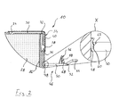
- einen Ausschnitt einer geschnittenen Seitenansicht der erfindungsgemäßen Tintenpatrone aus Fig. 1 unmittelbar nach deren Herstellung mit einem vergrößerten Ausschnitt X eines Details des Verriegelungshebels,
- Fig. 3
- eine teilweise geschnittene Seitenansicht der erfindungsgemäßen Tintenpatrone beim Einsetzen in eine Patronenaufnahme eines Tintenstrahldruckers,
- Fig. 4
- eine teilweise geschnittene Seitenansicht der erfindungsgemäßen Tintenpatrone nach dem Verriegeln in der Patronenaufnahme,
- Fig. 5
- einen der Ansicht nach Fig. 2 entsprechenden Ausschnitt einer geschnittenen Seitenansicht einer abgewandelten Ausführungsform der erfindungsgemäßen Tintenpatrone, und
- Fig. 6
- einen der Ansicht nach Fig. 2 entsprechenden Ausschnitt einer geschnittenen Seitenansicht einer weiteren abgewandelten Ausführungsform der erfindungsgemäßen Tintenpatrone.
- Fig. 1
- in perspective view of an ink cartridge according to the invention with a ventilation device which can be activated by a locking lever,
- Fig. 2
- 1 shows a detail of a sectioned side view of the ink cartridge according to the invention from FIG. 1 immediately after its production with an enlarged detail X of a detail of the locking lever, FIG.
- Fig. 3
- a partially sectioned side view of the ink cartridge according to the invention when inserted into a cartridge receptacle of an ink jet printer,
- Fig. 4
- a partially sectioned side view of the ink cartridge according to the invention after locking in the cartridge receptacle,
- Fig. 5
- a section corresponding to the view according to FIG 2 a sectional side view of a modified embodiment of the ink cartridge according to the invention, and
- Fig. 6
- a section corresponding to the view according to FIG. 2 a sectional side view of a further modified embodiment of the ink cartridge according to the invention.
Fig. 1 zeigt in perspektivischer Darstellung eine erfindungsgemäße Tintenpatrone 10. Die
Tintenpatrone 10 hat ein aus Polypropylen gefertigtes Gehäuse 12. An der Unterseite des
Gehäuses 12 ist ein Anschlußstutzen 14 angeformt, mit dem die Tintenpatrone 10 an
einen entsprechend ausgebildeten Anschluß eines nicht dargestellten Tintenstrahldruckers
anschließbar ist. Wie später noch erläutert wird, ist der Anschlußstutzen 14 durch eine
Folie (nicht dargestellt) verschlossen, die, während die Tintenpatrone 10 in den Tintenstrahldrucker
eingesetzt wird, von einem am Anschluß des Tintenstrahldruckers vorgesehenen
Anschlußdorn durchstoßen wird. An der in Fig. 1 links dargestellten Seitenfläche 16
des Gehäuses 12 ist eine Aufnahme 18 für einen Authentifizierungschip (gleichfalls nicht
dargestellt) vorgesehen.Fig. 1 shows a perspective view of an
Die Oberseite 20 des Gehäuses 12 ist durch einen Deckel 22 verschlossen. Etwa in der
Mitte des Deckels 22 ist eine gestrichelt dargestellte Öffnung 24 ausgebildet, die mit einer
im Gehäuse 12 ausgebildeten Tintenspeicherkammer 26 (vgl. Fig. 2 bis 6) in Strömungsverbindung
steht, in welcher ein poröser Tintenspeicher 28 zum Speichern flüssiger Tinte
aufgenommen ist. Die Öffnung 24 steht mit einem teilweise mäanderförmig verlaufenden
Kanal 30 (gleichfalls gestrichelt dargestellt) in Strömungsverbindung, welcher am Deckel
22 des Gehäuses 12 ausgenommen ist. Der Kanal 30 endet in einer Verbindungsöffnung
32 kleineren Durchmessers nahe der anderen Seitenfläche 34 des Gehäuses 12.The
Unmittelbar benachbart zur Oberseite 20 des Gehäuses 12 ist in dessen Seitenfläche 34
eine Ausgleichskammer 36 ausgebildet, die, wie beispielsweise Fig. 2 zeigt, an ihrem
oberen Ende offen und durch den Deckel 22 verschlossen ist. Die Verbindungsöffnung 32
am Deckel 22 ist dabei so am Deckel 22 ausgebildet, dass sie mit der Ausgleichskammer
36 in Strömungsverbindung steht. In die Ausgleichskammer 36 mündet eine an der
Seitenfläche 34 ausgebildete Belüftungsöffnung 38.Immediately adjacent to the top 20 of the
Die Öffnung 24, der Kanal 30, die Verbindungsöffnung 32 sowie die Belüftungsöffnung
38, die nach außen hin offen und durch eine gemeinsame Folie 40 abgedeckt sind, welche
mit dem Gehäuse 12 fluiddicht verklebt oder auf dieses aufgesiegelt ist, bilden gemeinsam
mit der Ausgleichskammer 38 eine Belüftungseinrichtung 42 zum Belüften der
Tintenspeicherkammer 26.The
An der Seitenfläche 34 des Gehäuses 12 ist eine Verriegelungseinrichtung 44 in Form
eines Verriegelungshebels 46 vorgesehen, dessen Aufbau nachfolgend unter Bezugnahme
auf Fig. 2 näher beschrieben wird.On the
Wie Fig. 2 zeigt, in der ein Ausschnitt der Tintenpatrone 10 aus Fig. 1 in geschnittener
Seitenansicht dargestellt ist, ist der Verriegelungshebel 46 durch ein Filmscharnier 48 an
die Außenseite des Gehäuses 12 angelenkt und um eine quer zur Seitenfläche 34 verlaufende
Schwenkachse A (vgl. Fig. 1) schwenkbar. Der Verriegelungshebel 46 hat einen
Biegeabschnitt 50, dessen Funktionsweise später noch im Detail erläutert wird, an dessen
freiem Ende eine parallel zur Schwenkachse A verlaufende Rasterhebung 52 ausgebildet
ist. An den Biegeabschnitt 50 ist nahe der Rasterhebung 52 ein Auslösehebel 54 angeformt.As shown in FIG. 2, in which a section of the
Mit geringem Abstand zum Auslösehebel 54 ist an der der Rasterhebung 52 abgewandten
Vorderseite des Verriegelungshebels 46 ein Betätigungsdorn 56 angeformt, welcher sich
etwa lotrecht von der Vorderseite des Verriegelungshebels 46 erhebt und aus drei spitz
zulaufenden, dreieckigen Flächenelementen 58 zusammengesetzt ist, welche an den
Verriegelungshebel 46 angeformt sind.At a short distance from the
Wie der vergrößerte Ausschnitt X in Fig. 2 zeigt, in dem in vergrößerter Darstellung der
Übergang des Filmscharniers 48 zwischen dem Gehäuse 12 und dem Biegeabschnitt 50
des Verriegelungshebels 46 dargestellt ist, bildet der Biegeabschnitt 50 eine rechtwinklig
zum Filmscharnier 48 verlaufende Kante 60, welche in eine Stützfläche 62 übergeht. Die
Stützfläche 62 liegt in einer sich parallel zur Schwenkachse A erstreckenden Ebene und
verläuft unter einem Winkel α von etwa 45° geneigt zu der in Fig. 2 oben gezeigten
Vorderseite des Biegeabschnittes 50As the enlarged section X in Fig. 2 shows, in the enlarged view of
Transition of the
Nachfolgend wird die Funktionsweise der erfindungsgemäßen Tintenpatrone 10 anhand
der in den Fig. 3 und 4 gezeigten, teilweise geschnittenen Seitenansichten näher erläutert.The operation of the
Die Tintenpatrone 10 wird in einer senkrechten Bewegung in die Patronenaufnahme 64
eingesetzt, wie durch den Pfeil angedeutet ist, um den Anschlußstutzen 14 mit dem
Anschluß (nicht dargestellt) des Druckers in bekannter Weise zu koppeln, wobei die an
dem Anschlußstutzen 14 vorgesehene Folie von einem am Anschluß des Tintenstrahldruckers
vorgesehenen Anschlußsdorn durchstoßen wird.The
Wie Fig. 3 zeigt, kommt der Verriegelungshebel 46 bei der Einführbewegung der Tintenpatrone
10 mit einer Kante 66 an der Patronenaufnahme 64 in Berührung, durch die der
Verriegelungshebel 46 in Richtung der Seitenfläche 34 des Gehäuses 12 gedrückt wird.
Dabei wird der Verriegelungshebel 46 in einer ersten Phase am Filmscharnier 48 um die
Schwenkachse A soweit geschwenkt, bis die Stützfläche 62 mit der Seitenfläche 34 des
Gehäuses 12 in Berührung kommt. Der Abschluß dieser ersten Phase ist in Fig. 3 gezeigt.As shown in Fig. 3, the
Bei der weiteren Einführbewegung der Tintenpatrone 10 in die Patronenaufnahme 64
kann der Verriegelungshebel 46 nicht mehr im Filmscharnier 48 geschwenkt werden,
sondern beginnt sich im Biegeabschnitt 50 in seiner Längsrichtung quer zur Schwenkachse
A zu biegen, wie Fig. 4 zeigt. Dabei wird der Betätigungsdorn 56 in die die Belüftungsöffnung
38 fluiddicht verschließende Folie 40 gedrückt und aktiviert dabei die Belüftungseinrichtung
42 der Tintenpatrone 10. Etwa gleichzeitig durchstößt der Anschlußdorn am
Anschluß des Tintenstrahldruckers (nicht dargestellt) die den Anschlußstutzen 14 verschließende
Folie.During the further insertion movement of the
Sobald die am Biegeabschnitt 50 ausgebildete Rasterhebung 52 an der Kante 66 vorbeigeführt
ist, springt der Verriegelungshebel 46 geringfügig zurück und kommt mit der als
Rastkante dienenden Kante 66 in Eingriff. Dabei wird der Betätigungsdorn 56 wieder
geringfügig aus der Belüftungsöffnung 38 herausgezogen, wobei die Folie 40 in ihrer
durchstoßenen und aufgeweiteten Stellung verbleibt. Insbesondere auch durch die
zwischen den Flächenelementen 58 ausgebildeten Aussparungen 68 kann Luft durch die
Belüftungsöffnung 36, die Ausgleichskammer 36, die Verbindungsöffnung 32, den Kanal
30 und die Öffnung 24 zwischen der Tintenspeicherkammer 26 und der Umgebung für
einen Druckausgleich hin und her strömen.As soon as the
Sollte Tinte aus dem Inneren des Gehäuses 12 durch den Kanal 30 aus der Tintenspeicherkammer
26 gelangen, wird sie in der Ausgleichskammer 36 aufgefangen und gelangt
nicht nach außen.Should ink from the interior of the
Um die Tintenpatrone 10 wieder zu lösen, muß der Verriegelungshebel 46 lediglich mit
Hilfe des Auslösehebels 54 kurzfristig so in Richtung der Tintenpatrone 10 umgebogen
werden, bis sich die Rasterhebung 52 am Verriegelungshebel 56 von der Kante 66 löst.
Anschließend kann die Tintenpatrone 10 in entgegengesetzter Richtung wieder aus der
Patronenaufnahme 64 entnommen werden. Sofern noch Tinte in der Tintenpatrone 10
enthalten ist, kann der Benutzer die Belüftungsöffnung 38 und gegebenenfalls den
Anschlußstutzen 14 durch Aufkleben einer mit der Tintenpatrone 10 mitgelieferten,
selbstklebenden Folie wieder verschlossen werden.To solve the
Die erfindungsgemäße Tintenpatrone 10 bietet den Vorteil, dass das Öffnen der Belüftungseinrichtung
42 und das Verriegeln der Tintenpatrone 10 mit Hilfe der Verriegelungseinrichtung
44 gekoppelt und in einer vorgegebenen definierten Reihenfolge abläuft. So
erfolgt das Öffnen der Belüftungsöffnung 42 erst unmittelbar bevor die Tintenpatrone 10
mit der Kante 66 verrastet wird. Dies hat den Vorteil, dass ein Druckausgleich der
Tintenspeicherkammer 26 erst dann erfolgt, wenn sich der Anschlußstutzen 14 der
Tintenpatrone 10 in der letzten Bewegungsphase seines Ankoppelvorganges an den
Anschluß des Tintenstrahldruckers befindet, so dass keine Tinte am Anschluß des Tintenstrahldruckers
vorbei aus der Tintenpatrone 10 austreten kann.The
In den Fig. 5 und 6 sind Abwandlungen der Tintenpatrone 10 dargestellt, die sich lediglich
durch die Art unterscheiden, in welcher die Belüftungsöffnung 38 vor dem Aktivieren der
Belüftungseinrichtung 42 verschlossen ist.In Figs. 5 and 6, variations of the
So zeigt Fig. 5 eine Abwandlung der Tintenpatrone 10, bei der die Belüftungsöffnung 42
anstelle mit der Folie 40 durch eine in die Belüftungsöffnung 38 bei der Herstellung des
Gehäuses 12 eingespritzte Kunststoffhaut 70 verschlossen ist. Auch hier wird die Kunststoffhaut
70 durch die Wirkung des Betätigungsdornes 56 durchstoßen und auf diese
Weise die Belüftungseinrichtung 42 aktiviert.Thus, Fig. 5 shows a modification of the
Bei der in Fig. 6 gezeigten Abwandlung der Tintenpatrone 10 ist die Belüftungsöffnung 38
durch eine Ventilanordnung in Form eines Kugelventils 72 verschlossen. Das Kugelventil
72 hat hierzu eine Ventilkugel 74, die durch eine sich in der Ausgleichskammer 36
abstützende Druckfeder 76 gegen die Innenumlaufkante der Belüftungsöffnung 38
vorgespannt ist und diese fluiddicht verschließt. Des weiteren ist bei dieser Abwandlung
der Betätigungsdorn 56 am Verriegelungshebel 46 durch ein Betätigungselement 78 in
Form eines angeformten Zylinders ersetzt.In the modification of the
Wird nun die in Fig. 6 gezeigte abgewandelte Tintenpatrone 10 in die Patronenaufnahme
64 eingesetzt, wird der Verriegelungshebel 46 in seine Verriegelungsstellung in der zuvor
beschriebenen Weise bewegt, wobei das Betätigungselement 78 mit der Ventilkugel 74
des Kugelventils 72 in Berührung kommt und diese in die Ausgleichskammer 36 drückt,
wodurch die Belüftungsöffnung 38 geöffnet wird. Wird die Tintenpatrone 10 wieder aus
der Patronenaufnahme 64 entnommen, wird das Betätigungselement 78 wieder aus der
Belüftungsöffnung 38 zurückgezogen, wobei die Ventilkugel 74 durch die Kraft der
Druckfeder 76 wieder in ihre Schließstellung zurückbewegt wird, in der sie die Belüftungsöffnung
38 fluiddicht verschließt.Now, the modified
Zusätzlich zu den bereits zuvor beschriebenen Abwandlungen sind noch weitere Ausführungsformen
und Abwandlungen der erfindungsgemäßen Tintenpatrone 10 denkbar.
Beispielsweise kann der Verriegelungshebel 46 als separates Bauteil ausgebildet sein,
dass an einer entsprechenden Lagerstelle an der Außenseite des Gehäuses 12 gelagert
ist. Ferner ist es denkbar, den Verriegelungshebel 46 mechanisch mit einer die Belüftungsöffnung
38 verschließenden Ventilanordnung, beispielsweise in Form eines die
Belüftungsöffnung 38 verschließenden Schiebers, mechanisch zu koppeln. In addition to the modifications already described above are still further embodiments
and modifications of the
- 1010
- Tintenpatroneink cartridge
- 1212
- Gehäusecasing
- 1414
- Anschlußstutzenconnecting branch
- 1616
- Seitenflächeside surface
- 1818
- Aufnahmeadmission
- 2020
- Oberseitetop
- 2222
- Deckelcover
- 2424
- Öffnungopening
- 2626
- TintenspeicherkammerInk storage chamber
- 2828
- Tintenspeicherink reservoir
- 3030
- Kanalchannel
- 3232
- Verbindungsöffnungconnecting opening
- 3434
- Seitenflächeside surface
- 3636
- Ausgleichskammercompensation chamber
- 3838
- Belüftungsöffnungventilation opening
- 4040
- Foliefoil
- 4242
- Belüftungseinrichtungaerator
- 4444
- Verriegelungseinrichtunglocking device
- 4646
- Verriegelungshebellocking lever
- 4848
- Filmscharnierfilm hinge
- 5050
- Biegeabschnittbending section
- 5252
- RasterhebungRast collection
- 5454
- Auslösehebelsear
- 5656
- Betätigungsdornactuating mandrel
- 5858
- Flächenelementesurface elements
- 6060
- Kanteedge
- 6262
- Stützflächesupport surface
- 6464
- Patronenaufnahme cartridge receiver
- 6666
- Kanteedge
- 6868
- Aussparungenrecesses
- 7070
- Hautskin
- 7272
- Kugelventilball valve
- 7474
- Ventilkugelvalve ball
- 7676
- Druckfedercompression spring
- 7878
- Betätigungselementactuator
- AA
- SchwenkacheSchwenkache
- αα
- Neigungswinkeltilt angle
Claims (16)
einem Gehäuse (12), in dem mindestens eine Tintenspeicherkammer (26) ausgebildet ist, einer am Gehäuse (12) vorgesehenen Belüftungseinrichtung (42), die nach ihrer Aktivierung das Gehäuseinnere zum Druckausgleich mit der Umgebung verbindet, und
einer am Gehäuse (12) vorgesehenen Verriegelungseinrichtung (44) zum Verriegeln der Tintenpatrone (10) in der Patronenaufnahme (64), die zwischen einer Verriegelungsstellung, in der sie mit der Patronenaufnahme (64) verriegelt ist, und einer Entriegelungsstellung beweglich ist,
dadurch gekennzeichnet, dass die Verriegelungseinrichtung (44) gleichzeitig als Betätigungsorgan für die Aktivierung der Belüftungseinrichtung (42) dient und bei ihrer Bewegung in ihre Verriegelungsstellung mit der Belüftungseinrichtung (42) in Wirkverbindung kommt, um diese zu aktivieren.Ink cartridge for insertion into a cartridge receptacle of an inkjet printer, with
a housing (12) in which at least one ink storage chamber (26) is formed, provided on the housing (12) ventilation means (42) which connects after activation of the housing interior for pressure equalization with the environment, and
a locking device (44) provided on the housing (12) for locking the ink cartridge (10) in the cartridge receptacle (64) movable between a locking position in which it is locked to the cartridge receptacle (64) and an unlocking position,
characterized in that the locking device (44) simultaneously serves as an actuator for the activation of the ventilation device (42) and in its movement into its locking position with the ventilation device (42) comes into operative connection to activate them.
Applications Claiming Priority (2)
| Application Number | Priority Date | Filing Date | Title |
|---|---|---|---|
| DE102004004558A DE102004004558B4 (en) | 2004-01-29 | 2004-01-29 | ink cartridge |
| DE102004004558 | 2004-01-29 |
Publications (3)
| Publication Number | Publication Date |
|---|---|
| EP1559559A2 true EP1559559A2 (en) | 2005-08-03 |
| EP1559559A3 EP1559559A3 (en) | 2007-06-06 |
| EP1559559B1 EP1559559B1 (en) | 2011-05-25 |
Family
ID=34638801
Family Applications (1)
| Application Number | Title | Priority Date | Filing Date |
|---|---|---|---|
| EP05001789A Expired - Lifetime EP1559559B1 (en) | 2004-01-29 | 2005-01-28 | Ink cartridge |
Country Status (3)
| Country | Link |
|---|---|
| EP (1) | EP1559559B1 (en) |
| AT (1) | ATE510694T1 (en) |
| DE (1) | DE102004004558B4 (en) |
Cited By (2)
| Publication number | Priority date | Publication date | Assignee | Title |
|---|---|---|---|---|
| EP1955851A1 (en) | 2007-02-07 | 2008-08-13 | Seiko Epson Corporation | Fluid container, recycling method of fluid container, method for piercing cover film of fluid container, piercing jig, and method for manufacturing fluid container |
| CN106560322A (en) * | 2015-10-06 | 2017-04-12 | 精工爱普生株式会社 | Liquid injection system, ventilation unit, liquid supply device |
Citations (4)
| Publication number | Priority date | Publication date | Assignee | Title |
|---|---|---|---|---|
| EP0792749A2 (en) | 1996-03-01 | 1997-09-03 | Canon Kabushiki Kaisha | Packaging structure for ink tank and ink tank packaged in such packaging structure |
| EP0685340B1 (en) | 1994-05-31 | 1999-08-18 | Canon Kabushiki Kaisha | Replaceable ink cartridge and seal structure thereof |
| JPH11268290A (en) | 1998-03-20 | 1999-10-05 | Seiko Epson Corp | Printer ink cartridge device |
| EP0803365B1 (en) | 1996-04-26 | 2001-07-18 | Pelikan Hardcopy Production AG | An ink cartridge for a printer |
Family Cites Families (6)
| Publication number | Priority date | Publication date | Assignee | Title |
|---|---|---|---|---|
| US4785314A (en) * | 1984-03-14 | 1988-11-15 | Canon Kabushiki Kaisha | Internally pressure-regulated ink supply |
| JPS60192639A (en) * | 1984-03-14 | 1985-10-01 | Canon Inc | Liquid jet recording unit |
| JP2000094710A (en) * | 1998-09-24 | 2000-04-04 | Seiko Epson Corp | Print head device, ink jet printer and ink cartridge |
| US6761441B2 (en) * | 2001-12-14 | 2004-07-13 | Monitek Electronics Limited | Ink cartridge |
| US20030184625A1 (en) * | 2002-04-02 | 2003-10-02 | Pui Kuong Lui | Ink cartridge |
| ATE396872T1 (en) * | 2002-06-11 | 2008-06-15 | Seiko Epson Corp | INK CARTRIDGE |
-
2004
- 2004-01-29 DE DE102004004558A patent/DE102004004558B4/en not_active Expired - Fee Related
-
2005
- 2005-01-28 AT AT05001789T patent/ATE510694T1/en active
- 2005-01-28 EP EP05001789A patent/EP1559559B1/en not_active Expired - Lifetime
Patent Citations (4)
| Publication number | Priority date | Publication date | Assignee | Title |
|---|---|---|---|---|
| EP0685340B1 (en) | 1994-05-31 | 1999-08-18 | Canon Kabushiki Kaisha | Replaceable ink cartridge and seal structure thereof |
| EP0792749A2 (en) | 1996-03-01 | 1997-09-03 | Canon Kabushiki Kaisha | Packaging structure for ink tank and ink tank packaged in such packaging structure |
| EP0803365B1 (en) | 1996-04-26 | 2001-07-18 | Pelikan Hardcopy Production AG | An ink cartridge for a printer |
| JPH11268290A (en) | 1998-03-20 | 1999-10-05 | Seiko Epson Corp | Printer ink cartridge device |
Cited By (8)
| Publication number | Priority date | Publication date | Assignee | Title |
|---|---|---|---|---|
| EP1955851A1 (en) | 2007-02-07 | 2008-08-13 | Seiko Epson Corporation | Fluid container, recycling method of fluid container, method for piercing cover film of fluid container, piercing jig, and method for manufacturing fluid container |
| US8162456B2 (en) | 2007-02-07 | 2012-04-24 | Seiko Epson Corporation | Fluid container, recycling method of fluid container, method for piercing cover film of fluid container, piercing jig, and method for manufacturing fluid container |
| CN106560322A (en) * | 2015-10-06 | 2017-04-12 | 精工爱普生株式会社 | Liquid injection system, ventilation unit, liquid supply device |
| EP3156237A1 (en) * | 2015-10-06 | 2017-04-19 | Seiko Epson Corporation | Liquid ejection system, ventilation unit, liquid supply apparatus |
| US9908352B2 (en) | 2015-10-06 | 2018-03-06 | Seiko Epson Corporation | Liquid ejection system, ventilation unit, liquid supply apparatus |
| CN106560322B (en) * | 2015-10-06 | 2020-01-07 | 精工爱普生株式会社 | Liquid injection system, ventilation unit, liquid supply device |
| CN110962460A (en) * | 2015-10-06 | 2020-04-07 | 精工爱普生株式会社 | Liquid injection system, ventilation unit, liquid supply device |
| CN110962460B (en) * | 2015-10-06 | 2021-01-05 | 精工爱普生株式会社 | Liquid ejecting system, ventilation unit, and liquid supply device |
Also Published As
| Publication number | Publication date |
|---|---|
| EP1559559A3 (en) | 2007-06-06 |
| DE102004004558B4 (en) | 2008-01-03 |
| EP1559559B1 (en) | 2011-05-25 |
| DE102004004558A1 (en) | 2005-10-13 |
| ATE510694T1 (en) | 2011-06-15 |
Similar Documents
| Publication | Publication Date | Title |
|---|---|---|
| DE69635529T2 (en) | Ink tank, ink container manufacturing method | |
| DE60313038T2 (en) | BOTTLE LOCK WITH CONTROLLED OPENING MOVEMENT | |
| DE60008169T2 (en) | Arrangement for a capless filler neck of a fuel tank | |
| DE102009047004B4 (en) | Device for opening and closing a fuel tank | |
| EP2398664B1 (en) | Safety element for a diesel fuel container to prevent filling of wrong fuel | |
| EP2300256B1 (en) | Insert element for a container suitable for filling with urea at a filling station | |
| DE69317543T2 (en) | Ink refill container and ink refill method using the same | |
| EP0094499A1 (en) | Vaporizer for insecticides, aromatics and/or other volatile active substances | |
| WO2012110335A1 (en) | Reclosable drinks can | |
| DE4237790C2 (en) | Self-closing container closure | |
| DE3716288A1 (en) | LOCKING DEVICE FOR A VALVE OR THE LOCK ENDING A CAVITY | |
| DE102018220347A1 (en) | Fuel flap device for vehicles | |
| WO2013170282A2 (en) | Stamp, in particular round stamp | |
| EP1559559B1 (en) | Ink cartridge | |
| DE102006031463A1 (en) | Filler neck for filling diesel fuel into a vehicle tank | |
| DE3232340C1 (en) | Self-closing fuel tank cap | |
| DE60211722T2 (en) | FILTRATION DEVICE WITH IMPROVED DRAIN ASSEMBLY AND THIS COMPREHENSIVE DIESEL FUEL SUPPLY | |
| DE69524799T2 (en) | Rollover valve for venting and safety of a vehicle fuel tank | |
| EP1481734B1 (en) | Closure for a spray head | |
| EP1556224B1 (en) | Ink cartridge to be mounted on a recording head | |
| WO2017108156A1 (en) | Air freshener apparatus for a vehicle | |
| DE19839225A1 (en) | Inkjet printer and swap body for printing ink | |
| DE102017127313A1 (en) | Plastic closure for containers | |
| DE102009029453A1 (en) | Device for receiving and delivering beverages, particularly beer, has stretch blow formed container for storing beverages, where container has impermeable wall | |
| DE102008031250A1 (en) | Insert element for diesel fuel tank for filling diesel fuel, comprises closing lid, which is folded away from its filler hole closing normal position by closing unit |
Legal Events
| Date | Code | Title | Description |
|---|---|---|---|
| PUAI | Public reference made under article 153(3) epc to a published international application that has entered the european phase |
Free format text: ORIGINAL CODE: 0009012 |
|
| AK | Designated contracting states |
Kind code of ref document: A2 Designated state(s): AT BE BG CH CY CZ DE DK EE ES FI FR GB GR HU IE IS IT LI LT LU MC NL PL PT RO SE SI SK TR |
|
| AX | Request for extension of the european patent |
Extension state: AL BA HR LV MK YU |
|
| PUAL | Search report despatched |
Free format text: ORIGINAL CODE: 0009013 |
|
| AK | Designated contracting states |
Kind code of ref document: A3 Designated state(s): AT BE BG CH CY CZ DE DK EE ES FI FR GB GR HU IE IS IT LI LT LU MC NL PL PT RO SE SI SK TR |
|
| AX | Request for extension of the european patent |
Extension state: AL BA HR LV MK YU |
|
| 17P | Request for examination filed |
Effective date: 20070615 |
|
| AKX | Designation fees paid |
Designated state(s): AT BE BG CH CY CZ DE DK EE ES FI FR GB GR HU IE IS IT LI LT LU MC NL PL PT RO SE SI SK TR |
|
| 17Q | First examination report despatched |
Effective date: 20100215 |
|
| GRAP | Despatch of communication of intention to grant a patent |
Free format text: ORIGINAL CODE: EPIDOSNIGR1 |
|
| GRAS | Grant fee paid |
Free format text: ORIGINAL CODE: EPIDOSNIGR3 |
|
| GRAA | (expected) grant |
Free format text: ORIGINAL CODE: 0009210 |
|
| AK | Designated contracting states |
Kind code of ref document: B1 Designated state(s): AT BE BG CH CY CZ DE DK EE ES FI FR GB GR HU IE IS IT LI LT LU MC NL PL PT RO SE SI SK TR |
|
| REG | Reference to a national code |
Ref country code: GB Ref legal event code: FG4D Free format text: NOT ENGLISH |
|
| REG | Reference to a national code |
Ref country code: CH Ref legal event code: EP |
|
| REG | Reference to a national code |
Ref country code: IE Ref legal event code: FG4D Free format text: LANGUAGE OF EP DOCUMENT: GERMAN |
|
| REG | Reference to a national code |
Ref country code: DE Ref legal event code: R096 Ref document number: 502005011415 Country of ref document: DE Effective date: 20110707 |
|
| REG | Reference to a national code |
Ref country code: CH Ref legal event code: PFA Owner name: PELIKAN HARDCOPY PRODUCTION AG Free format text: PELIKAN HARDCOPY PRODUCTION AG#LEESTRASSE 1#8132 EGG (CH) -TRANSFER TO- PELIKAN HARDCOPY PRODUCTION AG#HALDENSTRASSE 30#8620 WETZIKON (CH) |
|
| REG | Reference to a national code |
Ref country code: NL Ref legal event code: VDEP Effective date: 20110525 |
|
| RAP2 | Party data changed (patent owner data changed or rights of a patent transferred) |
Owner name: PELIKAN HARDCOPY PRODUCTION AG |
|
| PG25 | Lapsed in a contracting state [announced via postgrant information from national office to epo] |
Ref country code: PT Free format text: LAPSE BECAUSE OF FAILURE TO SUBMIT A TRANSLATION OF THE DESCRIPTION OR TO PAY THE FEE WITHIN THE PRESCRIBED TIME-LIMIT Effective date: 20110926 Ref country code: SE Free format text: LAPSE BECAUSE OF FAILURE TO SUBMIT A TRANSLATION OF THE DESCRIPTION OR TO PAY THE FEE WITHIN THE PRESCRIBED TIME-LIMIT Effective date: 20110525 Ref country code: LT Free format text: LAPSE BECAUSE OF FAILURE TO SUBMIT A TRANSLATION OF THE DESCRIPTION OR TO PAY THE FEE WITHIN THE PRESCRIBED TIME-LIMIT Effective date: 20110525 |
|
| PG25 | Lapsed in a contracting state [announced via postgrant information from national office to epo] |
Ref country code: ES Free format text: LAPSE BECAUSE OF FAILURE TO SUBMIT A TRANSLATION OF THE DESCRIPTION OR TO PAY THE FEE WITHIN THE PRESCRIBED TIME-LIMIT Effective date: 20110905 Ref country code: IS Free format text: LAPSE BECAUSE OF FAILURE TO SUBMIT A TRANSLATION OF THE DESCRIPTION OR TO PAY THE FEE WITHIN THE PRESCRIBED TIME-LIMIT Effective date: 20110925 Ref country code: SI Free format text: LAPSE BECAUSE OF FAILURE TO SUBMIT A TRANSLATION OF THE DESCRIPTION OR TO PAY THE FEE WITHIN THE PRESCRIBED TIME-LIMIT Effective date: 20110525 Ref country code: CY Free format text: LAPSE BECAUSE OF FAILURE TO SUBMIT A TRANSLATION OF THE DESCRIPTION OR TO PAY THE FEE WITHIN THE PRESCRIBED TIME-LIMIT Effective date: 20110525 Ref country code: FI Free format text: LAPSE BECAUSE OF FAILURE TO SUBMIT A TRANSLATION OF THE DESCRIPTION OR TO PAY THE FEE WITHIN THE PRESCRIBED TIME-LIMIT Effective date: 20110525 Ref country code: GR Free format text: LAPSE BECAUSE OF FAILURE TO SUBMIT A TRANSLATION OF THE DESCRIPTION OR TO PAY THE FEE WITHIN THE PRESCRIBED TIME-LIMIT Effective date: 20110826 |
|
| REG | Reference to a national code |
Ref country code: IE Ref legal event code: FD4D |
|
| PG25 | Lapsed in a contracting state [announced via postgrant information from national office to epo] |
Ref country code: NL Free format text: LAPSE BECAUSE OF FAILURE TO SUBMIT A TRANSLATION OF THE DESCRIPTION OR TO PAY THE FEE WITHIN THE PRESCRIBED TIME-LIMIT Effective date: 20110525 |
|
| REG | Reference to a national code |
Ref country code: DE Ref legal event code: R082 Ref document number: 502005011415 Country of ref document: DE Representative=s name: MEISSNER, BOLTE & PARTNER GBR, DE |
|
| PG25 | Lapsed in a contracting state [announced via postgrant information from national office to epo] |
Ref country code: EE Free format text: LAPSE BECAUSE OF FAILURE TO SUBMIT A TRANSLATION OF THE DESCRIPTION OR TO PAY THE FEE WITHIN THE PRESCRIBED TIME-LIMIT Effective date: 20110525 Ref country code: IE Free format text: LAPSE BECAUSE OF FAILURE TO SUBMIT A TRANSLATION OF THE DESCRIPTION OR TO PAY THE FEE WITHIN THE PRESCRIBED TIME-LIMIT Effective date: 20110525 Ref country code: CZ Free format text: LAPSE BECAUSE OF FAILURE TO SUBMIT A TRANSLATION OF THE DESCRIPTION OR TO PAY THE FEE WITHIN THE PRESCRIBED TIME-LIMIT Effective date: 20110525 |
|
| PG25 | Lapsed in a contracting state [announced via postgrant information from national office to epo] |
Ref country code: DK Free format text: LAPSE BECAUSE OF FAILURE TO SUBMIT A TRANSLATION OF THE DESCRIPTION OR TO PAY THE FEE WITHIN THE PRESCRIBED TIME-LIMIT Effective date: 20110525 Ref country code: SK Free format text: LAPSE BECAUSE OF FAILURE TO SUBMIT A TRANSLATION OF THE DESCRIPTION OR TO PAY THE FEE WITHIN THE PRESCRIBED TIME-LIMIT Effective date: 20110525 Ref country code: PL Free format text: LAPSE BECAUSE OF FAILURE TO SUBMIT A TRANSLATION OF THE DESCRIPTION OR TO PAY THE FEE WITHIN THE PRESCRIBED TIME-LIMIT Effective date: 20110525 Ref country code: RO Free format text: LAPSE BECAUSE OF FAILURE TO SUBMIT A TRANSLATION OF THE DESCRIPTION OR TO PAY THE FEE WITHIN THE PRESCRIBED TIME-LIMIT Effective date: 20110525 |
|
| REG | Reference to a national code |
Ref country code: DE Ref legal event code: R081 Ref document number: 502005011415 Country of ref document: DE Owner name: PELIKAN HARDCOPY PRODUCTION AG, CH Free format text: FORMER OWNER: PELIKAN HARDCOPY PRODUCTION AG, EGG, CH Effective date: 20120116 Ref country code: DE Ref legal event code: R082 Ref document number: 502005011415 Country of ref document: DE Representative=s name: MEISSNER, BOLTE & PARTNER GBR, DE Effective date: 20120116 Ref country code: DE Ref legal event code: R082 Ref document number: 502005011415 Country of ref document: DE Representative=s name: MEISSNER BOLTE PATENTANWAELTE RECHTSANWAELTE P, DE Effective date: 20120116 |
|
| PLBE | No opposition filed within time limit |
Free format text: ORIGINAL CODE: 0009261 |
|
| STAA | Information on the status of an ep patent application or granted ep patent |
Free format text: STATUS: NO OPPOSITION FILED WITHIN TIME LIMIT |
|
| PGFP | Annual fee paid to national office [announced via postgrant information from national office to epo] |
Ref country code: FR Payment date: 20120201 Year of fee payment: 8 Ref country code: CH Payment date: 20120124 Year of fee payment: 8 |
|
| 26N | No opposition filed |
Effective date: 20120228 |
|
| PG25 | Lapsed in a contracting state [announced via postgrant information from national office to epo] |
Ref country code: IT Free format text: LAPSE BECAUSE OF FAILURE TO SUBMIT A TRANSLATION OF THE DESCRIPTION OR TO PAY THE FEE WITHIN THE PRESCRIBED TIME-LIMIT Effective date: 20110525 |
|
| REG | Reference to a national code |
Ref country code: DE Ref legal event code: R097 Ref document number: 502005011415 Country of ref document: DE Effective date: 20120228 |
|
| PGFP | Annual fee paid to national office [announced via postgrant information from national office to epo] |
Ref country code: GB Payment date: 20120124 Year of fee payment: 8 |
|
| BERE | Be: lapsed |
Owner name: PELIKAN HARDCOPY PRODUCTION A.G. Effective date: 20120131 |
|
| PG25 | Lapsed in a contracting state [announced via postgrant information from national office to epo] |
Ref country code: MC Free format text: LAPSE BECAUSE OF NON-PAYMENT OF DUE FEES Effective date: 20120131 |
|
| PG25 | Lapsed in a contracting state [announced via postgrant information from national office to epo] |
Ref country code: BE Free format text: LAPSE BECAUSE OF NON-PAYMENT OF DUE FEES Effective date: 20120131 |
|
| REG | Reference to a national code |
Ref country code: AT Ref legal event code: MM01 Ref document number: 510694 Country of ref document: AT Kind code of ref document: T Effective date: 20120128 |
|
| PG25 | Lapsed in a contracting state [announced via postgrant information from national office to epo] |
Ref country code: AT Free format text: LAPSE BECAUSE OF NON-PAYMENT OF DUE FEES Effective date: 20120128 Ref country code: BG Free format text: LAPSE BECAUSE OF FAILURE TO SUBMIT A TRANSLATION OF THE DESCRIPTION OR TO PAY THE FEE WITHIN THE PRESCRIBED TIME-LIMIT Effective date: 20110825 |
|
| REG | Reference to a national code |
Ref country code: CH Ref legal event code: PL |
|
| GBPC | Gb: european patent ceased through non-payment of renewal fee |
Effective date: 20130128 |
|
| REG | Reference to a national code |
Ref country code: FR Ref legal event code: ST Effective date: 20130930 |
|
| PG25 | Lapsed in a contracting state [announced via postgrant information from national office to epo] |
Ref country code: LI Free format text: LAPSE BECAUSE OF NON-PAYMENT OF DUE FEES Effective date: 20130131 Ref country code: CH Free format text: LAPSE BECAUSE OF NON-PAYMENT OF DUE FEES Effective date: 20130131 |
|
| PG25 | Lapsed in a contracting state [announced via postgrant information from national office to epo] |
Ref country code: FR Free format text: LAPSE BECAUSE OF NON-PAYMENT OF DUE FEES Effective date: 20130131 Ref country code: GB Free format text: LAPSE BECAUSE OF NON-PAYMENT OF DUE FEES Effective date: 20130128 |
|
| PG25 | Lapsed in a contracting state [announced via postgrant information from national office to epo] |
Ref country code: TR Free format text: LAPSE BECAUSE OF FAILURE TO SUBMIT A TRANSLATION OF THE DESCRIPTION OR TO PAY THE FEE WITHIN THE PRESCRIBED TIME-LIMIT Effective date: 20110525 |
|
| PG25 | Lapsed in a contracting state [announced via postgrant information from national office to epo] |
Ref country code: LU Free format text: LAPSE BECAUSE OF NON-PAYMENT OF DUE FEES Effective date: 20120128 |
|
| PG25 | Lapsed in a contracting state [announced via postgrant information from national office to epo] |
Ref country code: HU Free format text: LAPSE BECAUSE OF FAILURE TO SUBMIT A TRANSLATION OF THE DESCRIPTION OR TO PAY THE FEE WITHIN THE PRESCRIBED TIME-LIMIT Effective date: 20050128 |
|
| PGFP | Annual fee paid to national office [announced via postgrant information from national office to epo] |
Ref country code: DE Payment date: 20150120 Year of fee payment: 11 |
|
| REG | Reference to a national code |
Ref country code: DE Ref legal event code: R119 Ref document number: 502005011415 Country of ref document: DE |
|
| PG25 | Lapsed in a contracting state [announced via postgrant information from national office to epo] |
Ref country code: DE Free format text: LAPSE BECAUSE OF NON-PAYMENT OF DUE FEES Effective date: 20160802 |