EP1559572A1 - Druckelement mit Identifikationsmittel und Verfahren zum Einbetten von Identifikationsmittel in einem Druckelement - Google Patents
Druckelement mit Identifikationsmittel und Verfahren zum Einbetten von Identifikationsmittel in einem Druckelement Download PDFInfo
- Publication number
- EP1559572A1 EP1559572A1 EP04106912A EP04106912A EP1559572A1 EP 1559572 A1 EP1559572 A1 EP 1559572A1 EP 04106912 A EP04106912 A EP 04106912A EP 04106912 A EP04106912 A EP 04106912A EP 1559572 A1 EP1559572 A1 EP 1559572A1
- Authority
- EP
- European Patent Office
- Prior art keywords
- sleeve
- printing member
- printing
- layer
- transponder
- Prior art date
- Legal status (The legal status is an assumption and is not a legal conclusion. Google has not performed a legal analysis and makes no representation as to the accuracy of the status listed.)
- Granted
Links
- 238000007639 printing Methods 0.000 title claims abstract description 162
- 238000000034 method Methods 0.000 title claims description 33
- 239000002184 metal Substances 0.000 claims abstract description 6
- 229910052751 metal Inorganic materials 0.000 claims abstract description 6
- 239000010410 layer Substances 0.000 claims description 80
- 239000011152 fibreglass Substances 0.000 claims description 42
- 239000000463 material Substances 0.000 claims description 30
- 239000003822 epoxy resin Substances 0.000 claims description 27
- 229920000647 polyepoxide Polymers 0.000 claims description 27
- 239000000758 substrate Substances 0.000 claims description 20
- 239000004814 polyurethane Substances 0.000 claims description 17
- 229920005989 resin Polymers 0.000 claims description 16
- 239000011347 resin Substances 0.000 claims description 16
- 229920002635 polyurethane Polymers 0.000 claims description 11
- 239000003365 glass fiber Substances 0.000 claims description 7
- 230000015572 biosynthetic process Effects 0.000 claims description 6
- 239000002131 composite material Substances 0.000 claims description 6
- 238000003754 machining Methods 0.000 claims description 5
- 239000002243 precursor Substances 0.000 claims description 5
- 238000004804 winding Methods 0.000 claims description 5
- 239000000470 constituent Substances 0.000 claims description 4
- 239000013078 crystal Substances 0.000 claims description 4
- 238000001514 detection method Methods 0.000 claims description 3
- 239000000835 fiber Substances 0.000 claims description 3
- 239000002356 single layer Substances 0.000 claims description 3
- OKTJSMMVPCPJKN-UHFFFAOYSA-N Carbon Chemical compound [C] OKTJSMMVPCPJKN-UHFFFAOYSA-N 0.000 claims description 2
- 239000004760 aramid Substances 0.000 claims description 2
- 229920003235 aromatic polyamide Polymers 0.000 claims description 2
- 230000005540 biological transmission Effects 0.000 claims description 2
- 229910052799 carbon Inorganic materials 0.000 claims description 2
- 238000010276 construction Methods 0.000 claims description 2
- 238000012544 monitoring process Methods 0.000 claims description 2
- 238000007598 dipping method Methods 0.000 claims 1
- 239000012792 core layer Substances 0.000 description 21
- 238000004519 manufacturing process Methods 0.000 description 11
- 239000004645 polyester resin Substances 0.000 description 8
- 229920001225 polyester resin Polymers 0.000 description 8
- 238000005452 bending Methods 0.000 description 5
- 238000010438 heat treatment Methods 0.000 description 5
- PXHVJJICTQNCMI-UHFFFAOYSA-N Nickel Chemical compound [Ni] PXHVJJICTQNCMI-UHFFFAOYSA-N 0.000 description 4
- 230000015556 catabolic process Effects 0.000 description 4
- 239000003086 colorant Substances 0.000 description 4
- 238000006731 degradation reaction Methods 0.000 description 4
- 229920001971 elastomer Polymers 0.000 description 4
- 238000005498 polishing Methods 0.000 description 4
- 229910000831 Steel Inorganic materials 0.000 description 3
- 229910052782 aluminium Inorganic materials 0.000 description 3
- XAGFODPZIPBFFR-UHFFFAOYSA-N aluminium Chemical compound [Al] XAGFODPZIPBFFR-UHFFFAOYSA-N 0.000 description 3
- 229920006231 aramid fiber Polymers 0.000 description 3
- 238000007646 gravure printing Methods 0.000 description 3
- 238000012986 modification Methods 0.000 description 3
- 230000004048 modification Effects 0.000 description 3
- 238000007645 offset printing Methods 0.000 description 3
- 239000010959 steel Substances 0.000 description 3
- 238000013519 translation Methods 0.000 description 3
- 229920002799 BoPET Polymers 0.000 description 2
- VYZAMTAEIAYCRO-UHFFFAOYSA-N Chromium Chemical compound [Cr] VYZAMTAEIAYCRO-UHFFFAOYSA-N 0.000 description 2
- 229920000271 Kevlar® Polymers 0.000 description 2
- 229920005830 Polyurethane Foam Polymers 0.000 description 2
- XUIMIQQOPSSXEZ-UHFFFAOYSA-N Silicon Chemical compound [Si] XUIMIQQOPSSXEZ-UHFFFAOYSA-N 0.000 description 2
- 230000002411 adverse Effects 0.000 description 2
- 229910052804 chromium Inorganic materials 0.000 description 2
- 239000011651 chromium Substances 0.000 description 2
- 238000005253 cladding Methods 0.000 description 2
- 230000006835 compression Effects 0.000 description 2
- 238000007906 compression Methods 0.000 description 2
- 230000008602 contraction Effects 0.000 description 2
- 229910052759 nickel Inorganic materials 0.000 description 2
- 229920003023 plastic Polymers 0.000 description 2
- 239000004033 plastic Substances 0.000 description 2
- 229920000728 polyester Polymers 0.000 description 2
- 239000011496 polyurethane foam Substances 0.000 description 2
- 238000012545 processing Methods 0.000 description 2
- 229910052710 silicon Inorganic materials 0.000 description 2
- 239000010703 silicon Substances 0.000 description 2
- 238000012546 transfer Methods 0.000 description 2
- 238000011282 treatment Methods 0.000 description 2
- RYGMFSIKBFXOCR-UHFFFAOYSA-N Copper Chemical compound [Cu] RYGMFSIKBFXOCR-UHFFFAOYSA-N 0.000 description 1
- 229920000784 Nomex Polymers 0.000 description 1
- 239000004411 aluminium Substances 0.000 description 1
- 230000004323 axial length Effects 0.000 description 1
- 239000011230 binding agent Substances 0.000 description 1
- 230000000740 bleeding effect Effects 0.000 description 1
- 238000004891 communication Methods 0.000 description 1
- 230000001010 compromised effect Effects 0.000 description 1
- 239000004020 conductor Substances 0.000 description 1
- 229910052802 copper Inorganic materials 0.000 description 1
- 239000010949 copper Substances 0.000 description 1
- 238000013481 data capture Methods 0.000 description 1
- 230000001066 destructive effect Effects 0.000 description 1
- 238000011161 development Methods 0.000 description 1
- 230000018109 developmental process Effects 0.000 description 1
- 238000003745 diagnosis Methods 0.000 description 1
- 238000010017 direct printing Methods 0.000 description 1
- 230000000694 effects Effects 0.000 description 1
- 238000005516 engineering process Methods 0.000 description 1
- 239000006260 foam Substances 0.000 description 1
- 238000005259 measurement Methods 0.000 description 1
- 230000007246 mechanism Effects 0.000 description 1
- 239000000203 mixture Substances 0.000 description 1
- 239000004763 nomex Substances 0.000 description 1
- 230000003287 optical effect Effects 0.000 description 1
- 238000003825 pressing Methods 0.000 description 1
- 238000004080 punching Methods 0.000 description 1
- 230000011664 signaling Effects 0.000 description 1
- 239000002904 solvent Substances 0.000 description 1
- 238000003892 spreading Methods 0.000 description 1
- 238000012360 testing method Methods 0.000 description 1
- 230000001131 transforming effect Effects 0.000 description 1
Images


Classifications
-
- B—PERFORMING OPERATIONS; TRANSPORTING
- B41—PRINTING; LINING MACHINES; TYPEWRITERS; STAMPS
- B41F—PRINTING MACHINES OR PRESSES
- B41F13/00—Common details of rotary presses or machines
- B41F13/08—Cylinders
-
- B—PERFORMING OPERATIONS; TRANSPORTING
- B41—PRINTING; LINING MACHINES; TYPEWRITERS; STAMPS
- B41F—PRINTING MACHINES OR PRESSES
- B41F27/00—Devices for attaching printing elements or formes to supports
- B41F27/10—Devices for attaching printing elements or formes to supports for attaching non-deformable curved printing formes to forme cylinders
- B41F27/105—Devices for attaching printing elements or formes to supports for attaching non-deformable curved printing formes to forme cylinders for attaching cylindrical printing formes
-
- B—PERFORMING OPERATIONS; TRANSPORTING
- B41—PRINTING; LINING MACHINES; TYPEWRITERS; STAMPS
- B41N—PRINTING PLATES OR FOILS; MATERIALS FOR SURFACES USED IN PRINTING MACHINES FOR PRINTING, INKING, DAMPING, OR THE LIKE; PREPARING SUCH SURFACES FOR USE AND CONSERVING THEM
- B41N1/00—Printing plates or foils; Materials therefor
-
- B—PERFORMING OPERATIONS; TRANSPORTING
- B41—PRINTING; LINING MACHINES; TYPEWRITERS; STAMPS
- B41N—PRINTING PLATES OR FOILS; MATERIALS FOR SURFACES USED IN PRINTING MACHINES FOR PRINTING, INKING, DAMPING, OR THE LIKE; PREPARING SUCH SURFACES FOR USE AND CONSERVING THEM
- B41N6/00—Mounting boards; Sleeves Make-ready devices, e.g. underlays, overlays; Attaching by chemical means, e.g. vulcanising
-
- B—PERFORMING OPERATIONS; TRANSPORTING
- B41—PRINTING; LINING MACHINES; TYPEWRITERS; STAMPS
- B41N—PRINTING PLATES OR FOILS; MATERIALS FOR SURFACES USED IN PRINTING MACHINES FOR PRINTING, INKING, DAMPING, OR THE LIKE; PREPARING SUCH SURFACES FOR USE AND CONSERVING THEM
- B41N7/00—Shells for rollers of printing machines
-
- B—PERFORMING OPERATIONS; TRANSPORTING
- B29—WORKING OF PLASTICS; WORKING OF SUBSTANCES IN A PLASTIC STATE IN GENERAL
- B29C—SHAPING OR JOINING OF PLASTICS; SHAPING OF MATERIAL IN A PLASTIC STATE, NOT OTHERWISE PROVIDED FOR; AFTER-TREATMENT OF THE SHAPED PRODUCTS, e.g. REPAIRING
- B29C53/00—Shaping by bending, folding, twisting, straightening or flattening; Apparatus therefor
- B29C53/56—Winding and joining, e.g. winding spirally
- B29C53/58—Winding and joining, e.g. winding spirally helically
- B29C53/60—Winding and joining, e.g. winding spirally helically using internal forming surfaces, e.g. mandrels
- B29C53/62—Winding and joining, e.g. winding spirally helically using internal forming surfaces, e.g. mandrels rotatable about the winding axis
- B29C53/64—Winding and joining, e.g. winding spirally helically using internal forming surfaces, e.g. mandrels rotatable about the winding axis and moving axially
-
- B—PERFORMING OPERATIONS; TRANSPORTING
- B29—WORKING OF PLASTICS; WORKING OF SUBSTANCES IN A PLASTIC STATE IN GENERAL
- B29C—SHAPING OR JOINING OF PLASTICS; SHAPING OF MATERIAL IN A PLASTIC STATE, NOT OTHERWISE PROVIDED FOR; AFTER-TREATMENT OF THE SHAPED PRODUCTS, e.g. REPAIRING
- B29C53/00—Shaping by bending, folding, twisting, straightening or flattening; Apparatus therefor
- B29C53/80—Component parts, details or accessories; Auxiliary operations
- B29C53/8008—Component parts, details or accessories; Auxiliary operations specially adapted for winding and joining
- B29C53/8066—Impregnating
-
- B—PERFORMING OPERATIONS; TRANSPORTING
- B41—PRINTING; LINING MACHINES; TYPEWRITERS; STAMPS
- B41N—PRINTING PLATES OR FOILS; MATERIALS FOR SURFACES USED IN PRINTING MACHINES FOR PRINTING, INKING, DAMPING, OR THE LIKE; PREPARING SUCH SURFACES FOR USE AND CONSERVING THEM
- B41N2207/00—Location or type of the layers in shells for rollers of printing machines
- B41N2207/02—Top layers
-
- B—PERFORMING OPERATIONS; TRANSPORTING
- B41—PRINTING; LINING MACHINES; TYPEWRITERS; STAMPS
- B41N—PRINTING PLATES OR FOILS; MATERIALS FOR SURFACES USED IN PRINTING MACHINES FOR PRINTING, INKING, DAMPING, OR THE LIKE; PREPARING SUCH SURFACES FOR USE AND CONSERVING THEM
- B41N2207/00—Location or type of the layers in shells for rollers of printing machines
- B41N2207/04—Intermediate layers
-
- B—PERFORMING OPERATIONS; TRANSPORTING
- B41—PRINTING; LINING MACHINES; TYPEWRITERS; STAMPS
- B41P—INDEXING SCHEME RELATING TO PRINTING, LINING MACHINES, TYPEWRITERS, AND TO STAMPS
- B41P2200/00—Printing processes
- B41P2200/10—Relief printing
- B41P2200/12—Flexographic printing
-
- B—PERFORMING OPERATIONS; TRANSPORTING
- B41—PRINTING; LINING MACHINES; TYPEWRITERS; STAMPS
- B41P—INDEXING SCHEME RELATING TO PRINTING, LINING MACHINES, TYPEWRITERS, AND TO STAMPS
- B41P2200/00—Printing processes
- B41P2200/30—Heliography
Definitions
- the present invention relates to a printing member and to a method in accordance with the introduction to the corresponding independent claims.
- printing member means any member for directly or indirectly transferring information onto a miscellaneous support by flexographic, copper-plate or offset printing. Consequently said term comprises any one of the following elements: a printing cylinder in general such as a steel cylinder, a steel cylinder with chromium plated surface, a steel cylinder with rubber cladding, an aluminium cylinder with anodised or non-anodized surface; a printing sleeve to be mounted, in known manner such as by deformation with compressed air or by other means, on a mandrel (possibly of radially deformable type) rotating about its longitudinal axis, said sleeve being of composite material such as glass fibre, aramid fibre, carbon fibre or combinations of these fibres, said sleeve of fibre or composite material being clad with a polyurethane or rubber layer or presenting a chromium plated covering surface, or being clad with polyester or epoxy resin; a nickel sle
- Said printing member can present print characters or images on its outer surface (characters or images which may be directly formed on it or provided on plates or blocks fixed to said surface in any known manner) to consequently enable direct printing of said characters or images on a suitable support in a flexographic or copper-plate printing machine; alternatively said printing member can be used as a roller in an intermediate roller group of a flexographic, rotogravure, combining, spreading or offset machine to transfer ink in known manner onto a cylinder provided with said print characters (or images), said roller hence enabling said characters or images to be indirectly printed on a suitable support or substrate.
- a printing sleeve that is generally cylindrical in shape can be mounted onto a rotatable printing cylinder of a printing machine for printing images (or characters) onto the substrate.
- Most commercial printing machines have numerous printing cylinders and thus require numerous printing sleeves.
- Air-mounting is one common way of mounting a printing sleeve.
- Air-mounting generally refers to the placement of a printing sleeve onto a printing cylinder by supplying pressurized air between the sleeve and the cylinder.
- the printing sleeve has an inner surface diameter that is slightly smaller than the outer surface diameter of the printing cylinder. The difference in these diameters is a dimension known as the "interference fit".
- the diameter of at least the inner surface of the printing sleeve can be slightly expanded so that the sleeve can be mounted onto and/or removed from a printing cylinder. Maintaining the integrity of the interference fit is crucial to avoid slippage of the sleeve and resulting smearing or other unacceptable degradation of the image that is printed by the sleeve.
- an air-mountable printing sleeve can be formed from multiple concentric layers.
- most printing jobs involve an "image repeat", which is the circumferential length of the image that is to be printed one or more times on a substrate.
- the circumference of a printing sleeve must be large enough to contain one or more image repeats.
- different printing jobs may involve image repeats that differ in size, and consequently, different printing jobs may require printing sleeve repeats that also differ in size. For instance, a larger sleeve repeat size requires a printing sleeve with a larger circumferences or outer diameter for the same printing cylinder diameter.
- the outer surface diameter of the printing sleeve must be large enough to yield the larger sleeve repeat size.
- printing sleeves resulting from multiple layers that increase the radial thickness of the sleeve are generally used to provide the necessary radial thickness.
- the multi-layer printing sleeve has the effect of increasing the outer diameter of the sleeve to provide a larger repeat size so that the sleeve can be mounted on a smaller diameter printing cylinder that is already available in inventory. The thicker the sleeves then the greater the inertial mass of the rotating sleeve and the greater the danger of slippage if the interference fit should become compromised during the life of the sleeve.
- each printing member information aimed at defining the physical characteristics (for example type, dimensions, characteristics of its constituent material or materials or of those of each cladding layer presented) or related to a previous use and such, for example, as to enable definition of a probable life span or of the need to subject said member to a mechanical operation (for example grinding) which would prolong its useful life.
- this information (particularly if related to the physical characteristics of the printing member) is provided on labels or punchings which are separated from said member immediately prior to its initial use or which become illegible after a few uses.
- one type of multi-layered sleeve that is currently used in the art includes an innermost core layer that is formed from wound fiberglass coated with epoxy resin. After a first run of fiberglass tape coated with epoxy resin has been wound around a cylindrically shaped forming mandrel, a paper label having a thickness that is both uniform throughout the label and less than one millimeter is laid on this first run and covered with a second run of fiberglass tape coated with epoxy resin. Such label is provided with information concerning the ultimate sleeve that is to be formed. So typically, the innermost core layer would not be formed until it was known what type of sleeve was going to be built, so that the label could be created with the proper information and then embedded into the sleeve.
- the prior art multi-layered sleeve also can contain one or more layers that add thickness to the sleeve.
- materials such as rigid polyurethane foam or other forms of polyurethane (e.g., ISA-PUR 2330 and ISA-PUR 2340 which are sold by H.B. Fuller Austria, NOMEX® which is sold by DUPONT, and honeycomb structures) are utilized by the prior art sleeve.
- the thickness of such additional layers can vary depending on the particular image repeat utilized.
- other outer layers are also sometimes disposed on the outer surface of these layers, thereby further increasing the inertial mass of the sleeve and placing more importance on maintaining the interference fit of the sleeve.
- Gravure and flexographic printing machines can produce images that have multiple different colors.
- each printing sleeve In mounting each printing sleeve on its mandrel of the printing machine for such multi-color printing jobs, it is important that each printing sleeve be mounted in registry with each other printing sleeve so that the final printed image with all of the colors does not have one colored portion of the image bleeding into another colored portion of the image. Registration of each printing sleeve must be achieved not only circumferentially but also axially (side-to-side on the mandrel).
- the printing sleeve In a conventional printing sleeve that carries a printing plate for use in creating an image on a conventional flexographic printing machine or in a conventional printing sleeve that is etched with an image for use in a gravure printing machine, the printing sleeve has a notch in the sleeve.
- the mandrel has a pin, and the printing sleeve is mounted on the mandrel with the pin surrounded by the notch in the printing sleeve. Registration of each printing sleeve is thus achieved by locating the sleeve's notch relative to the mandrel's pin.
- the printing machine has an encoder on the servo-drive that indexes each mandrel so that the pin on mandrel points straight up at the 12 o'clock position at the beginning of each printing run of the machine. This is how the registration of the multi-color images is effected with conventional printing sleeves and printing machines.
- the notch becomes wallowed out and cannot be reliably located relative to the pin on the mandrel. Indeed, the pin of mandrel can be broken off with careless handling of the sleeves.
- Each of these conditions of sleeve wear and pin damage renders the conventional manner of registration of the printing sleeve unacceptably inaccurate.
- Users of the printing sleeve must rely on less efficient methods for achieving the same registration of the sleeve on the mandrel of the printing machine. These less efficient methods can involve wastage of the underlying printing substrate during manual efforts to achieve the desired registration of the multiple color job on the substrate.
- An object of the invention is therefore to provide an improved printing member.
- Another object is to provide a printing member of the stated type which enables easy reading of these data or information even after numerous years of use.
- a further object is to provide a printing member of the stated type which also enables updating of the data relevant to its use, said updating allowing subsequent reading of all information concerning the previously used data regarding said member, of all information relative to mechanical operations which may have been carried out on said member (for example surface grinding), of all information relative to the wear of said member, and of all other information necessary and useful in understanding its reliability and its possible life for further use.
- a further object is to provide a method for obtaining the above cited printing member.
- an object of the invention is to provide said method which is reliable and which can be carried out with the knowledge and means which do not negatively affect the manufacturing time and cost of said printing member.
- Another object is to provide a method which enables effecting the desired registration of said member on a printing machine for producing multi-color on the substrate that is being printed.
- a printing sleeve of the present invention contains identification means such as, for example, an RF transponder that includes an RFID chip that is embedded in a layer of the sleeve that is composed of a generally rigid and relatively expandable material.
- identification means such as, for example, an RF transponder that includes an RFID chip that is embedded in a layer of the sleeve that is composed of a generally rigid and relatively expandable material.
- the invention also relates to a method of making said printing sleeves for use in flexographic or gravure printing applications.
- the printing sleeve can include a thin-walled sleeve that can stand alone or be used to form the innermost core layer of a multi-layer sleeve.
- the thin-walled sleeve or innermost core layer of the printing sleeve desirably can be formed of an expandable, high rigidity material such as aramid fiber bonded with epoxy resin or polyester resin; reinforced polymeric material such as hardened glass fiber bonded with epoxy resin or polyester resin or similar known materials.
- a thin-walled sleeve that is formed by winding successive runs of fiberglass tape that has been coated with epoxy resin and wound around a forming mandrel is provided with identification means, such as an RF transponder.
- identification means such as an RF transponder.
- a first run of fiberglass tape that has been coated with epoxy resin is helically wound around the length of a cylindrically shaped, rigid forming mandrel.
- An RF transponder is then placed on the outer surface of this first layer.
- a second layer of resin-coated fiberglass tape is wound around and covers the first layer of resin-coated fiberglass tape and around the transponder that is disposed on top of the first layer of resin-coated fiberglass tape.
- the transponder is thus disposed beneath at least a second layer of resin-imbued fiberglass tape that forms a thin-walled sleeve (and/or the innermost core of a sleeve) made in accordance with the present invention with but two runs of fiberglass tape.
- additional layers of resin-coated fiberglass tape desirably may be added on top of the second run until the desired thickness of resin-coated fiberglass has been attained for the particular sleeve that is desired.
- the identification means or transponder in the thin-walled sleeve provides the possibility of an improved method of effecting the desired registration of the sleeves on a gravure or flexographic printing machine for producing multi-color images on the substrate that is being printed.
- This improved method is accomplished by providing the printing machine with detection means, such as a positioning scanner and desirably a positioning scanner at each printing station.
- the positioning scanner (or similar detection means) is electronically connected to the controller of the printing machine. The positioning scanner detects the precise location of the microprocessor in the transponder and provides this information to the controller of the printing machine.
- the printing machine can index the position of each sleeve so that all of the sleeves are in common registration to produce the desired image on the substrate that is being printed. In this way, all of the colors in the image are in proper registration from the very first image that is printed on the substrate by the machine.
- the improved method thereby eliminates the wastage of the substrate that occurs during manual registration with conventional sleeves.
- FIGS. 1 and 2 show a printing member defined by a printing cylinder 1 (roller or printing sleeve).
- Said cylinder comprises a body 2 having a longitudinal through hole 3 enabling the cylinder 1 to be arranged, in the manner known to the expert of the art and hence not described, on a known rotary support, for example of the radially expandable type, not shown.
- the body 2 is of single layer type, i.e. it consists of a single metal, plastic or composite material (in that case, including binding resin).
- the body 2 presents an outer surface 5 (carrying the print characters or images) distant from an inner wall 6 (bounding the through hole 3), between which there is a thickness 7. Finally the body 2 presents opposing end faces 8 and 9 perpendicular to the surfaces 5 and 6.
- identification means defined by means 10 for identifying useful data related to at least one characteristic of the cylinder and to a physical value of this latter (for example, dimensions, characteristics of the constituent material of the cylinder 1, type of cylinder) or to a previous use of the cylinder (for example, the hours of previous use) or to a previous mechanical machining operation to which it has been subjected after its construction and, for example, after one or more uses.
- the data stored in the means 10 comprise a unique absolute code which, when displayed or transmitted remotely (by radio frequency), allows access (via suitable reading instruments defined hereinafter) to a plurality of the aforestated characteristics.
- One or more characteristics of the cylinder 1 are identified via said identification means, said means consequently defining means for identifying the cylinder.
- the identification means 10 comprise a microprocessor unit or transponder 30 (see Fig. 8A and Fig. 8B) which is preferably powered from outside the cylinder 1 when the data stored in it are to be read. In this case, this power is supplied to the identification means 10 from outside the cylinder 1 and without contact with the means themselves.
- these latter are preferably of the known radio frequency identification system type and comprise, as will be explained below, the microprocessor unit in which the data identifying the cylinder 1 are stored and can also be read remotely by a radio frequency reading member 15 (of known type).
- This member 15 is connected to a processor 16 (acting as recording means) by which the read data can be displayed (by monitor 17) to a user and possibly recorded on a suitable support (for example a compact disc - CD).
- the processor 16 can store information relative to the characteristics of the printing member or cylinder 1 and/or relative to dimensional and/or machining modifications which the cylinder has undergone. Consequently, the memory content of the recording means 16 can be updated by the user according to his own requirements: for example, by feeding data into it relative to the life of the product, grinding and/or wear data or any other data considered opportune by the user to facilitate the use of the sleeve.
- the identification means 10 are inserted into a seat 18 provided within the thickness 7 of the body 2 and, in the case of Figures 1 and 2, reclosed by a suitable closure element 13; this latter can be of material of the same type as the constituent material of the body 2 or can be of composite material (for example glass fibre when the body 2 is of metal).
- Figures 3 and 4 show variants of the invention.
- Figure 3 shows a cylinder 1 in which the seat 18 for the identification means 10 is provided in proximity to the lateral face 9 of the cylinder 1.
- the identification means are hence located within the cylinder 1.
- the identification means 10 of Figure 3 can also have the thickness of a label and be positioned directly on the face 9.
- this position of the identification means 10 does not negatively affect the use of the printing member, nor can said means be damaged by this use because they are positioned on a side of said member which is not subjected to impacts or stresses during said use.
- the cylinder 1 is a printing sleeve comprising, in known manner, two layers 1A and 1 B which are torsionally rigid with each other and are defined by different materials (for example one layer is of glass fibre and relative binder, such as epoxy resin, while the other 1 B is of polyurethane).
- the identification means 10 are directly embedded in the polyurethane and are in a position such as to be identified on the surface 5 of the cylinder in order to enable them to be easily found.
- the layers of the cylinder or sleeve 1 can also be more than two or the cylinder (or sleeve) 1 can be a single layer or multi-layer support for a plate-carrying sleeve which is mounted (for example by compressed air deformation) on the surface 5 of the cylinder 1 (for example provided with through holes between the surfaces 5 and 6 to feed compressed air from the hole 3 to the surface 5 and hence mount said sleeve on it).
- this code can be inserted into the body 2 of said cylinder, the code also being able to be read remotely via the reader 15.
- the identification means 10 can also be associated with the exterior or interior of the cylinder 1 (for example on a lateral face 8 or 9 or in the hole 3 on the wall 6) instead of being inserted into its thickness 7. This variant is also to be considered as falling with in the scope of the present document.
- the recording means or processor 16 cooperate with separate specific identification members of the cylinder 1 defined by at least one code (alphanumerical, bar or other) associated with an outer surface, preferably with a lateral face 8 or 9, of the body 2.
- code alphanumerical, bar or other
- On reading this code (visually or by a suitable reader, for example by an optical reader), it can be fed into the processor 16 and act on its memory to insert data concerning the cylinder and related to its use.
- Said memory already contains the cylinder data provided by the manufacturer, namely the dimensional, body material and other data. These data can hence be updated by the user.
- each cylinder 1 (roller or sleeve) produced is identified by a label for example with a bar code, positioned on the face 8 or 9 of the body 2.
- a unique absolute code corresponding to the part serial number is reproduced on the identification means.
- a file carrying all the production and technological characteristics of the individual part is provided on a computer support, associated with each code (stored in the microprocessor unit or carried by the identification means).
- This file can be updated each time the user acquires a new sleeve or roller, in order to create a complete database for the equipment available.
- rollers/sleeves When the user uses the equipment, all the technical data of the roller or sleeve can be obtained by reading the code, updating the production runs and production times and any other information considered necessary and useful to file; a search can be made through the rollers/sleeves on the basis of production runs or working times or of any other parameter considered significant.
- the user has a radio frequency network system
- communication between the reader and the roller/sleeve database can take place in real time, allowing direct dialogue between the operator working in the roller store and the database, with possible identification of the cylinder with the desired characteristics being sought.
- the code is associated with the said microprocessor unit, the required cylinder can be very simply identified remotely.
- the essential data of the sought roller can be memorized in the reader, to then precisely identify it by code correspondence.
- the invention provides a printing member of the aforesaid type with which useful information for its use is always associated, as heretofore described. This information is advantageously and preferably updatable.
- the present invention is also directed to an improved method of making printing sleeves for use in flexographic or gravure printing and indirect or offset printing.
- a thin-walled printing sleeve 1 which also can become the innermost core layer 1 of a multi-layer sleeve, in accordance with the present invention now will be described with reference initially to Fig. 5.
- the description will refer to the formation of a stand-alone thin-walled sleeve 1 such as shown in Fig. 6D.
- the description is equally applicable to the formation of an innermost core layer 1 of a multi-layer sleeve 40 such as shown in Fig. 7 unless otherwise indicated.
- a thin-walled sleeve 1 is formed from wound fiberglass tape that has been coated with epoxy resin and wound around a forming mandrel 19.
- any of a variety of materials used in forming printing sleeves can be utilized to form the thin-walled sleeve 1 that also can become a core layer 1.
- the thin-walled sleeve (or core layer) 1 is formed of an expandable, high rigidity material. Such materials are expandable so that the thin-walled sleeve 1 can be repeatedly expanded and contracted without adverse consequences. Such non-destructive expansion and contraction permits the inner surface of the sleeve 1 to form an interference fit with the outer surface of a rotary support. The degree of permitted expansion and contraction need not be so large as to be detectable by the naked eye.
- compositions that are suitable for composing the thin-walled sleeve 1 include, but are not limited to, aramid fiber bonded with epoxy resin or polyester resin; reinforced polymeric material such as hardened glass fiber bonded with epoxy resin or polyester resin, the latter two also known as fiberglass reinforced epoxy resin or fiberglass reinforced polyester; DUPONT@ MYLAR® or tri-laminate KEVLAR® that may optionally be reinforced with a resin, such as epoxy resin or polyester resin; carbon-reinforced epoxy resin; and the like.
- the radial thickness of the thin-walled sleeve 1 also can vary, depending on the desired application.
- the thin-walled sleeve 1 can have a thickness between about 0.020 to about 0.100 inches (0,0508 - 0,254 cm), with the larger thickness being used for sleeves with greater diameters and/or axial length.
- the thin-walled sleeve 1 is made from wound fiberglass that is coated with epoxy resin having a thickness of 0.040 inches (0,1016 cm).
- a first run 21 of fiberglass tape 20 that has been coated with epoxy resin 25 has been helically wound around the length of a cylindrically shaped, rigid forming mandrel 19 with each successive wrapping positioned so as to slightly overlap the prior adjacent wrapping.
- the outer surface of the mandrel 19 can be shaped as a right cylinder or can be tapered, depending on the desired shape of the innermost surface of the thin-walled sleeve 1.
- the forming mandrel 19 is rotated to wind a first layer 21 of fiberglass tape 20 that has been passed through a vessel 24 holding a bath of epoxy resin 25.
- the mandrel is translated back and forth along the axis of rotation of the mandrel.
- This reciprocating axial translation of the mandrel 19 is schematically indicated in Fig. 5 by the double-headed arrow designated 26 and results in a helical, slightly overlapped winding pattern, with the pitch determined by the speed of rotation and the speed of translation.
- a phantom representation of the mandrel 19 covered by the first layer of resin-imbued fiberglass tape 21 is shown by the chain-dashed outline toward the left of the view shown in Fig. 5.
- the phantom representation illustrates the mandrel 19 at one extreme position of the mandrel's axial translation.
- a transponder 30 (defining an identification means) is placed on the outer surface of this first layer 21 that is to form the thin-walled sleeve 1. Because of the tackiness of the epoxy resin, the transponder 30 will adhere to this outer surface of the first layer 21 of resin-imbued fiberglass tape 20.
- a second layer 22 of resin-coated fiberglass tape 20 is wound around and covers the first layer of resin-coated fiberglass tape and around the transponder 30 that is disposed on top of the first layer of resin-coated fiberglass tape.
- the dashed lines schematically indicate that the transponder 30 is disposed beneath at least a second layer 22 of resin-imbued fiberglass tape that forms a thin-walled sleeve 1 (and/or the innermost core 1 of a sleeve) that is made in accordance with the present invention with only two runs of fiberglass tape 20.
- additional layers of resin-coated fiberglass tape may be added on top of the second run 22 until the desired thickness of resin-coated fiberglass has been attained for the particular application.
- the thickest portion of the transponder 30 should be less than about one millimeter thick, which is measured in the radial direction when the transponder 30 is positioned on the first run 21 of resin-coated fiberglass. In this way, the presence of the transponder 30 between the first and second layers of the thin-walled sleeve 1 does not result in any detectable degradation of the performance of the finished thin-walled sleeve 1. For example, there is no functionally appreciable degradation in the interference fit between the inner surface 6 (Fig. 6D) of the sleeve 1 and the exterior surface of the rotary support on which the sleeve becomes mounted during operation of the printing machine. Desirably, the thickest portion of the transponder should be less than about one half millimeter thick.
- Transponder 30 is part of what are known as Automatic Identification and Data Capture (AIDC) products.
- Transponder 30 can include a radio frequency (RF) device, which in one exemplary embodiment may correspond to an RFID transponder (or RFID tag), such as a TAG-ITTM HF-I transponder inlay offered for sale by Texas Instruments of Dallas, Texas.
- RF device may be made up of at least a silicon chip 32 and signaling components for relaying RF signals to a remote location.
- the silicon chip 32 can include a memory device, which desirably may be a digital memory device.
- the RF device also comprises an antenna 34.
- the RF devices in accordance with the present technology may be either active devices, which transmit signals directly to a scanner at a remote location, or passive devices, which reflect or backscatter RF transmission from a separate interrogator or reader device.
- the transponder 30 can provide location information to a positioning scanner that enables the positioning scanner to determine the position of the transponder relative to the positioning scanner and provide this positioning information to a microprocessor or machine controller of the printing machine.
- the RF signals relayed by the RF device of transponder 30 may in some embodiments be characterized by selected frequency levels in the UHF band of 300 MHz to 3000 MHz. Such RF signals may include a variety of predetermined information, including various preprogrammed identification information for a sleeve structure, as mentioned below in more detail.
- the RF device also may desirably include an application-specific integrated circuit (ASIC) for further customizing the identification information available to a user.
- ASIC application-specific integrated circuit
- Additional sensor elements such as those suitable for monitoring the temperature, pressure, and other conditions within a sleeve, may be integrated with or coupled to the RF device of the transponder 30 so that measurements of a sleeve's physical conditions also may be included in the RF signals communicated by the RF device.
- the length of a generally rectangular-shaped transponder 30 can be about 76 millimeters.
- the width of such a transponder 30 can be on the order of 48 millimeters.
- the width of the antenna 34 of the transponder can be on the order of 45 millimeters.
- the center point of the memory chip 32 of the transponder 30 can be positioned about 23.4 millimeters from the longer side of the transponder.
- the distance of the center point of the memory chip 32 can be disposed about 17.3 millimeters from the shorter side of the transponder 30 depicted in Fig. 8A.
- This configuration of the transponder 30 is merely exemplary and not intended to be restrictive of the different configurations that could be used in accordance with the present invention.
- the transponder's thickness which is measured in the radial direction when the transponder 30 is positioned on the first run 21 of resin-coated fiberglass, should be less than about one millimeter and more preferably less than about one half millimeter. As shown in Fig. 9, the thickness of the transponder 30 is not uniform throughout the entire transponder. As shown in Fig. 5, the thickness of the transponder's memory chip 32 depicted in Fig. 4A is about 0.355 millimeters, and the thickness of the antenna 34 is about 0.085 millimeters.
- the antenna size of this embodiment of the transponder 30 depicted in Fig. 8A can be about 45 millimeters by 76 millimeters.
- the antenna 34 desirably is formed of a conductive material such as aluminum.
- the substrate of the transponder desirably can be formed of polyethylenetherephtalate (PET) and thus is flexible to a bending radius that desirably is about eighteen (18) millimeters.
- PET polyethylenetherephtalate
- the memory chip 32 desirably can be provided with a programmable memory that has 2000 bits organized in 64 by 34 bit blocks.
- the supported standard of the transponder 30 can be ISO 15693-2,-3 with a recommended operating frequency of 13.56 megahertz.
- the antenna 34 of the transponder 30 surrounds the memory chip 32, it is not important how the antenna 34 is oriented on the surface of the first layer 21 of fiberglass tape imbued with resin.
- the transponder 30 has the ability to receive information from the sleeve manufacturer as well as from the client that purchases the sleeve to use on the printing machine. Users of the sleeve find it desirable to write to the transponder 30 such information as how long the sleeve has been run and accordingly the number of feet with each use, the image that was mounted on the sleeve 1, the roll of the printing machine that the sleeve was mounted on, and any other particularities that are characteristic of the sleeve that might help the user save time in mounting the sleeve on the machine and preparing the sleeve for the printing process. Other information that is useful to write to the transponder 30 of the sleeve could include the job on which the sleeve was used and any problems that were encountered during the last usage of the sleeve.
- a generally square-shaped transponder 30 is depicted schematically in Fig. 8B and is not uniformly the same thickness throughout the entire transponder, but does not exceed about one half millimeter in thickness at any point in the transponder.
- the width of such a transponder 30 can be on the order of 48 millimeters, and the length is the same.
- the width of the antenna 34 of the transponder can be on the order of 45 millimeters.
- the center point of the memory chip 32 of the transponder 30 can be positioned about 23.4 millimeters from the side of the transponder. Similarly, the distance of the center point of the memory chip can be disposed about 17.3 millimeters from the front of the transponder 30 depicted in Fig. 8B.
- the substrate of the square-shaped transponder desirably can be formed of polyethylenetherephtalate (PET) and thus is flexible to a bending radius that desirably is about eighteen (18) millimeters.
- PET polyethylenetherephtalate
- the thin-walled sleeve 1 that results from the process of the present invention will include an RF transponder 30 that will be embedded into the final thin-walled sleeve 1.
- the thin-walled sleeve 1 can also be made in a manner similar to the printing sleeves in U.S. Patent No. 4,144,812 to Julian or 4,903,597 to Hoage, et al. .
- a thin-walled sleeve 1 such as shown in Fig. 6D can be used as the innermost core layer 1 of a multi-layered sleeve 40 that can have several additional layers 41, 42, which are schematically indicated by the dashed lines and are shown partially cut away. Though only two additional layers are depicted in Fig. 7, more than two additional layers can be used.
- a multi-layered sleeve 40 such as shown in Fig. 7, the finishing of the innermost core layer 1 such as shown in Fig. 6D will prepare the exterior surface 5 (Fig. 6D) of the innermost core layer 1 for the application of one of the subsequent additional layers (such as layers 41, 42 if only two are involved) that will compose the final multi-layered sleeve 40.
- the formation of these additional layers also will typically involve heat treatments and mechanical operations of grinding and polishing. Such treatments and operations also can subject the multi-layer sleeve 40 to various expansions, compressions and twisting contortions.
- One or more additional layer(s) can be used to add further thickness to the multi-layered sleeve 40 and/or as a cover layer for the sleeve 40.
- any number, size, shape, and/or type of additional layers can be used in the present invention, so long as the resulting printing sleeve can be air-mounted onto a printing cylinder; sleeves which can be used in this invention are described in the following US patents: Nos. 5,782,181; 5,735,206; 5,819,657; 6,691,614; and 6,688,226.
- One such additional layer can be formed from a generally rigid, relatively expandable material.
- the phrase "rigid" refers to a material having a certain Shore hardness.
- the additional layer can be made from a material having a Shore D hardness of about 20 to about 85, and in some embodiments, from about 45 to about 50.
- the additional layer can contain a polyurethane material having a Shore D hardness between about 45 to about 50.
- One such polyurethane material may be obtained from H.B. Fuller Austria under the tradename ISA-PUR 2330.
- the additional layer can also be relatively expandable.
- the term "expandable" refers to a material that can expand a certain radial distance upon the application of air at a certain pressure.
- the printing sleeves typically expand in a radial direction between about 0.0015 to about 0.0045 inches (0,00381 - 0,01143 cm), and in some embodiments, between about 0.0025 to about 0.0035 inches (0,00635 - 0,00889 cm).
- a printing sleeve having a diameter less than 7 inches (17,78 cm) expands, in a radial direction, about 0.0025 inches (0,00635 cm).
- a printing sleeve having an inner diameter greater than 7 inches (17,78 cm) expands, in a radial direction, about 0.0035 inches (0,00889 cm).
- the thickness of this additional layer can generally vary. In most embodiments, for example, the thickness of this additional layer is between about 0.125 to about 1.50 inches (0,3175 - 3,81 cm), and in some embodiments, between about 0.125 inches (0,3175 cm) to about 1.00 inches (2,54 cm).
- Suitable materials that can be utilized in forming other additional outer layers include, but are not limited to, aramid fiber bonded with epoxy resin or polyester resin; reinforced polymeric material such as hardened glass fiber bonded with epoxy resin or polyester resin, the latter two also known as fiberglass reinforced epoxy resin or fiberglass reinforced polyester; DUPONT® MYLAR® or tri-laminate KEVLAR®; a polyurethane material (e.g., ISA-PUR 2330 or ISA-PUR 2340 from H.B. Fuller Austria under the tradename ISA-PUR 2330); elastomeric rubber materials; elastomeric polyurethane materials; polyurethane expanded foam; open cell polyurethane foam; nickel; copper; carbon-reinforced epoxy resin; and the like.
- a metal outer layer such as an aluminum extruded layer, can also be included.
- an alternative embodiment of a sleeve 50 made in accordance with the present invention can include an elongated piezoelectric crystal 51 that acts as a transducer that supplies an electrical signal to the memory chip of the transponder 30 (or identification means).
- the crystal 51 is laid on the first run 21 of fiberglass tape 20 along with the transponder 30.
- the crystal 51 is electrically connected to the transponder 30, which may be provided with an analog-to-digital converter and a digital-to-analog converter, either by hardware or software.
- the transponder 30 can be used to record for later download and/or transmit in real time, pressures and the type of bending stresses that the sleeve 50 is undergoing during usage.
- the transponder in the thin-walled sleeve enables an improved method of effecting the desired registration of the sleeves on a gravure or flexographic printing machine for producing multi-color images on the substrate that is being printed.
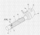
- a thin-walled sleeve 1 made in accordance with the present invention is mounted on a rotary support or mandrel 61 of a printing machine that is schematically designated by the numeral 60.
- the sleeve 1 carries a printing plate 45 shown in phantom (dashed line) with an image 46 (or character) that is also shown in phantom.
- the printing machine 60 is provided with a positioning scanner 62 that is mounted at the printing station of the mandrel 61. Desirably, a separate positioning scanner 62 will be provided at each printing station of the machine 60.
- the positioning scanner 62 is electronically connected to the controller 63 of the printing machine 60.
- the positioning scanner 62 detects the precise location of the microprocessor chip 32 in the transponder 30 and provides this information to the controller 63 of the printing machine 60. Using this information, the printing machine 60 can index the position of each sleeve so that all of the sleeves at all of the printing stations of the machine are in common registration to produce the desired image on the substrate that is being printed. In this way, all of the colors in the image (or the characters) are in proper registration from the very first image that is printed on the substrate by the machine. The improved method thereby eliminates the wastage of the substrate that occurs during manual registration of conventional sleeves.
- a label 31 can be placed on the outer surface of this first layer 21 that is to form the final thin-walled sleeve 1.
- the label 31, which desirably is formed of paper that carries data expressed in ink markings, also can be covered with a second run of fiberglass tape coated with epoxy resin.
- the label 31 also can be embedded within the thin-walled sleeve 1 as the different layers of fiberglass tape are wound around the prior layers of fiberglass tape. Indeed, as shown in Fig. 6B, such a label 31 can be disposed between the same two layers that sandwich the transponder 30.
- such a label 31 can be disposed between different layers than the ones that sandwich the transponder 30.
- the label 31 can include a machine-readable bar code or information that is readable by the naked human eye and readily comprehensible by the human reader, as desired.
- Such label has a thickness of less than one millimeter and typically is provided with information concerning the ultimate sleeve that is to be formed.
- the innermost core layer 1 of a multi-layer sleeve can be formed before it is known what type of sleeve is going to be built, and the label 31 could be created with generic information that is not particular to any specific customer or type of sleeve or merely provided with a trademark. In an alternative case such as shown in Fig. 6D, the label 31 can be omitted altogether.
- a second, subsidiary cylinder receives the inked data (characters or images) to be printed (i.e., "the impression") from a first cylinder and transfers the data to a substrate or web of paper or other material (for example plastic), that is interposed between the blanket cylinder and a third cylinder or pressing (or printing) cylinder.
- the surface of the blanket cylinder passes through a bath of solvents that wash the residual ink from the surface of the blanket cylinder.
Landscapes
- Engineering & Computer Science (AREA)
- Mechanical Engineering (AREA)
- Printing Plates And Materials Therefor (AREA)
- Manufacture Or Reproduction Of Printing Formes (AREA)
- Burglar Alarm Systems (AREA)
- Printers Or Recording Devices Using Electromagnetic And Radiation Means (AREA)
- Discharging, Photosensitive Material Shape In Electrophotography (AREA)
- Golf Clubs (AREA)
- Chemical And Physical Treatments For Wood And The Like (AREA)
- Adhesives Or Adhesive Processes (AREA)
- Inspection Of Paper Currency And Valuable Securities (AREA)
Priority Applications (1)
| Application Number | Priority Date | Filing Date | Title |
|---|---|---|---|
| PL04106912T PL1559572T3 (pl) | 2004-01-27 | 2004-12-22 | Człon drukujący wyposażony w elementy identyfikujące i sposób osadzania wspomnianych elementów we wspomnianym członie |
Applications Claiming Priority (4)
| Application Number | Priority Date | Filing Date | Title |
|---|---|---|---|
| ITMI20040109 ITMI20040109A1 (it) | 2004-01-27 | 2004-01-27 | Organo da stampa provvisto di mezzi di identificazione definiti da o collegabili a mezzi di registrazione aggiornabili di dati relativi a tale organo ed utili per l'impiego di quest'ultimo |
| ITMI20040109 | 2004-01-27 | ||
| US56474604P | 2004-04-23 | 2004-04-23 | |
| US564746P | 2004-04-23 |
Publications (2)
| Publication Number | Publication Date |
|---|---|
| EP1559572A1 true EP1559572A1 (de) | 2005-08-03 |
| EP1559572B1 EP1559572B1 (de) | 2007-08-29 |
Family
ID=34655274
Family Applications (1)
| Application Number | Title | Priority Date | Filing Date |
|---|---|---|---|
| EP04106912A Expired - Lifetime EP1559572B1 (de) | 2004-01-27 | 2004-12-22 | Druckelement mit Identifikationsmittel und Verfahren zum Einbetten von Identifikationsmittel in einem Druckelement |
Country Status (7)
| Country | Link |
|---|---|
| US (2) | US7308854B2 (de) |
| EP (1) | EP1559572B1 (de) |
| AT (1) | ATE371540T1 (de) |
| DE (1) | DE602004008571T2 (de) |
| DK (1) | DK1559572T3 (de) |
| ES (1) | ES2288663T3 (de) |
| PL (1) | PL1559572T3 (de) |
Cited By (9)
| Publication number | Priority date | Publication date | Assignee | Title |
|---|---|---|---|---|
| DE102006006136A1 (de) * | 2006-02-10 | 2007-08-23 | Koenig & Bauer Aktiengesellschaft | Systeme zur Überprüfung der Bestückung eines Druckformmagazins und ein System zur Zuführung mindestens einer in einem Druckformmagazin gespeicherten Druckform zu einem Zylinder |
| DE102006024280A1 (de) * | 2006-05-24 | 2007-11-29 | Man Roland Druckmaschinen Ag | Druckmaschinenmesssystem |
| US7331287B2 (en) | 2003-03-28 | 2008-02-19 | Koenig & Bauer Aktiengesellschaft | Devices for storing a blanket to be exchanged on a cylinder of a printing machine |
| DE102007052295A1 (de) * | 2007-10-31 | 2009-05-07 | Manroland Ag | Druckmaschine mit einer Vorrichtung zur kontaktlosen Messdatenerfassung |
| EP1826004A3 (de) * | 2006-02-22 | 2010-12-08 | Rolf-Peter Lehner | Vorrichtung zur Einstellung und/oder Identifizierung von auf Formzylindern einer Druckmaschine aufgebrachten Druckformen |
| EP2583830A1 (de) | 2011-10-20 | 2013-04-24 | Janoschka Holding GmbH | Transpondereinsatz an Druckwalzen |
| EP2604431A3 (de) * | 2011-12-16 | 2015-09-23 | Gallus Stanz- und Druckmaschinen GmbH | Tiefdruckwerk mit Bahnspannungsausgleich und Verfahren zum Warten eines solchen Tiefdruckwerks |
| ITUA20163968A1 (it) * | 2016-05-31 | 2017-12-01 | Trelleborg Coated Systems Italy S P A | Vasca di impregnazione di un tessuto e dispositivo di fabbricazione di un cilindro per macchina da stampa che include detta vasca di impregnazione |
| CN108128667A (zh) * | 2016-12-01 | 2018-06-08 | 何政豪 | 具无线射频识别的智能型卷盘 |
Families Citing this family (19)
| Publication number | Priority date | Publication date | Assignee | Title |
|---|---|---|---|---|
| CA2572787A1 (en) * | 2004-07-01 | 2006-01-12 | Powerid Ltd. | Battery-assisted backscatter rfid transponder |
| WO2006077732A1 (ja) * | 2005-01-18 | 2006-07-27 | Konica Minolta Medical & Graphic, Inc. | 印刷版材料、製版方法、印刷方法、平版印刷版材料集合体用包装体、平版印刷版材料の集合体及び製版印刷方法 |
| JP4438955B2 (ja) | 2005-04-01 | 2010-03-24 | トヨタ自動車株式会社 | 蓄圧装置 |
| US20080272890A1 (en) * | 2005-06-30 | 2008-11-06 | Zvi Nitzan | Battery-assisted backscatter RFID transponder |
| ATE459470T1 (de) † | 2006-10-23 | 2010-03-15 | Fischer & Krecke Gmbh | Verfahren, monatagevorrichtung und steuereinheit zur justierung einer walze in einer druckmaschine |
| DE202007007835U1 (de) * | 2007-05-21 | 2008-09-25 | Day International, Inc., Dayton | Dünnwandige Verbundhülse |
| DE102007059507B4 (de) * | 2007-12-11 | 2012-01-26 | Fischer & Krecke Gmbh | Druckmaschine mit Walzensensor |
| US20090165662A1 (en) * | 2007-12-31 | 2009-07-02 | Nim-Cor, Inc. | Bridge mandrels for anilox and print roller applications and techniques for making them |
| US20100307356A1 (en) * | 2008-02-04 | 2010-12-09 | Felice Rossini | Bridged sleeve/cylinder and method of making same for web offset printing machines |
| US20090193991A1 (en) | 2008-02-04 | 2009-08-06 | Felice Rossini | Blanket sleeve and cylinder and method of making same |
| EP2090944B1 (de) * | 2008-02-14 | 2011-10-26 | Siemens Aktiengesellschaft | Druckmaschinen und Verfahren zur kabellosen Datenerfassung von den mit RFID ausgestattenen internen Komponenten |
| US8181572B2 (en) * | 2008-12-15 | 2012-05-22 | Mark Van Denend | System and method for matching a corrected sleeve to a substrate printing cylinder |
| JP5955539B2 (ja) * | 2010-12-03 | 2016-07-20 | イー・アイ・デュポン・ドウ・ヌムール・アンド・カンパニーE.I.Du Pont De Nemours And Company | 印刷で使用するシリンダ形状要素を作製する方法 |
| US9346258B2 (en) * | 2012-05-02 | 2016-05-24 | Printing Research, Inc. | Method for cleaning anti-marking jackets |
| DE102012214824A1 (de) * | 2012-08-21 | 2014-02-27 | Ball Europe Gmbh | Verfahren und Vorrichtung zum Ausrichten von Druckplatten auf Druckzylindern |
| CN110894029A (zh) * | 2019-11-25 | 2020-03-20 | 昆山聚创新能源科技有限公司 | 电池极片收放卷结构 |
| EP3988309B1 (de) * | 2020-10-22 | 2026-04-15 | Heidelberger Druckmaschinen AG | Verfahren zum betreiben einer flexodruckmaschine, flexodruckmaschine, system und hülse |
| ES2999608T3 (en) * | 2020-10-22 | 2025-02-26 | Heidelberger Druckmasch Ag | Printing machine with a printing roller and an anilox roller or an anilox sleeve |
| EP3988305A1 (de) * | 2020-10-22 | 2022-04-27 | Heidelberger Druckmaschinen AG | Verfahren zum betreiben einer flexodruckmaschine, flexodruckmaschine, system und hülse für eine flexodruckform |
Citations (12)
| Publication number | Priority date | Publication date | Assignee | Title |
|---|---|---|---|---|
| US4144812A (en) | 1975-01-08 | 1979-03-20 | Strachan & Henshaw Limited | Printing sleeves |
| US4903597A (en) | 1988-10-24 | 1990-02-27 | Lavalley Industries, Inc. | Printing sleeves and methods for mounting and dismounting |
| US5048353A (en) * | 1990-03-01 | 1991-09-17 | Beloit Corporation | Method and apparatus for roll profile measurement |
| US5323704A (en) * | 1992-07-30 | 1994-06-28 | Heidelberg-Harris Gmbh | Device for the identification of a flexible roller shell |
| US5735206A (en) | 1995-03-20 | 1998-04-07 | Erminio Rossini, Spa | Deformable mandrels for rotary printing cylinders |
| US5782181A (en) | 1995-03-14 | 1998-07-21 | Erminio Rossini S.P.A. | Concentric double sleeve for a rotary printing cylinder |
| US5819657A (en) | 1996-03-11 | 1998-10-13 | Ermino Rossini, Spa | Air carrier spacer sleeve for a printing cylinder |
| US6110085A (en) * | 1997-04-11 | 2000-08-29 | Felix Bottcher Gmbh & Co. | Coated roller with permanent identification and method for providing such identification |
| JP2001353842A (ja) * | 2000-06-14 | 2001-12-25 | Dainippon Printing Co Ltd | 非接触式データキャリアおよびシリンダ装置 |
| US20020056392A1 (en) * | 2000-10-09 | 2002-05-16 | Man Roland Druckmaschinen Ag | Apparatus and method for storing sleeves for rotary printing machines |
| US6688226B2 (en) | 2000-10-03 | 2004-02-10 | Erminio Rossini, S.P.A. | Sleeve for blanket cylinder of an indirect or offset printing machine and method of making said sleeve |
| US6691614B2 (en) | 2000-06-16 | 2004-02-17 | Rossini North America, Inc. | Multi-layered printing sleeve |
Family Cites Families (15)
| Publication number | Priority date | Publication date | Assignee | Title |
|---|---|---|---|---|
| DE3543704A1 (de) * | 1985-12-11 | 1987-06-19 | Md Papierfabrik Pasing Nicolau | Vorrichtung und verfahren zum bedrucken einer bahn |
| CA2068629C (en) * | 1991-05-14 | 1996-05-07 | James B. Vrotacoe | Gapless tubular printing blanket |
| US5860360A (en) * | 1996-12-04 | 1999-01-19 | Day International, Inc. | Replaceable printing sleeve |
| ATE313817T1 (de) * | 1998-12-25 | 2006-01-15 | Asahi Kasei Chemicals Corp | Flexodruckplatte und deren rohling |
| DE10032281A1 (de) * | 2000-07-03 | 2002-01-17 | Heidelberger Druckmasch Ag | Verfahren zur Beeinflussung einer Emulsion in einer Druckmaschine |
| US7037865B1 (en) * | 2000-08-08 | 2006-05-02 | Moldite, Inc. | Composite materials |
| JP4141122B2 (ja) * | 2000-11-06 | 2008-08-27 | サカセ・アドテック株式会社 | インフレータブル構造及びインフレータブル構造を備えたアレーアンテナ及びインフレータブル構造の展開方法 |
| US6823795B2 (en) * | 2001-05-16 | 2004-11-30 | Mars, Inc. | Method and apparatus for forming multicolor registered images on edible pieces |
| US7081815B2 (en) * | 2001-08-23 | 2006-07-25 | Battelle Memorial Institute | Radio frequency security system, method for a building facility or the like, and apparatus and methods for remotely monitoring the status of fire extinguishers |
| US7011021B2 (en) * | 2001-09-10 | 2006-03-14 | Day International, Inc. | Printing blanket sleeve with replaceable printing surface |
| US6799510B2 (en) * | 2002-05-02 | 2004-10-05 | New Hudson Corporation | Thin-walled bridge mandrel |
| US20030233557A1 (en) * | 2002-06-13 | 2003-12-18 | Zimmerman Thomas Guthrie | Electronic signature verification method and apparatus |
| JP4090798B2 (ja) * | 2002-06-21 | 2008-05-28 | 大日本印刷株式会社 | 熱転写受像シートロール |
| US6799511B2 (en) * | 2002-12-03 | 2004-10-05 | Day International, Inc. | Gapless compressible cylinder assembly |
| US7159654B2 (en) * | 2004-04-15 | 2007-01-09 | Varco I/P, Inc. | Apparatus identification systems and methods |
-
2004
- 2004-12-22 DK DK04106912T patent/DK1559572T3/da active
- 2004-12-22 PL PL04106912T patent/PL1559572T3/pl unknown
- 2004-12-22 AT AT04106912T patent/ATE371540T1/de not_active IP Right Cessation
- 2004-12-22 DE DE602004008571T patent/DE602004008571T2/de not_active Expired - Lifetime
- 2004-12-22 EP EP04106912A patent/EP1559572B1/de not_active Expired - Lifetime
- 2004-12-22 ES ES04106912T patent/ES2288663T3/es not_active Expired - Lifetime
-
2005
- 2005-01-26 US US11/043,427 patent/US7308854B2/en not_active Expired - Lifetime
-
2007
- 2007-07-24 US US11/782,364 patent/US20080011173A1/en not_active Abandoned
Patent Citations (12)
| Publication number | Priority date | Publication date | Assignee | Title |
|---|---|---|---|---|
| US4144812A (en) | 1975-01-08 | 1979-03-20 | Strachan & Henshaw Limited | Printing sleeves |
| US4903597A (en) | 1988-10-24 | 1990-02-27 | Lavalley Industries, Inc. | Printing sleeves and methods for mounting and dismounting |
| US5048353A (en) * | 1990-03-01 | 1991-09-17 | Beloit Corporation | Method and apparatus for roll profile measurement |
| US5323704A (en) * | 1992-07-30 | 1994-06-28 | Heidelberg-Harris Gmbh | Device for the identification of a flexible roller shell |
| US5782181A (en) | 1995-03-14 | 1998-07-21 | Erminio Rossini S.P.A. | Concentric double sleeve for a rotary printing cylinder |
| US5735206A (en) | 1995-03-20 | 1998-04-07 | Erminio Rossini, Spa | Deformable mandrels for rotary printing cylinders |
| US5819657A (en) | 1996-03-11 | 1998-10-13 | Ermino Rossini, Spa | Air carrier spacer sleeve for a printing cylinder |
| US6110085A (en) * | 1997-04-11 | 2000-08-29 | Felix Bottcher Gmbh & Co. | Coated roller with permanent identification and method for providing such identification |
| JP2001353842A (ja) * | 2000-06-14 | 2001-12-25 | Dainippon Printing Co Ltd | 非接触式データキャリアおよびシリンダ装置 |
| US6691614B2 (en) | 2000-06-16 | 2004-02-17 | Rossini North America, Inc. | Multi-layered printing sleeve |
| US6688226B2 (en) | 2000-10-03 | 2004-02-10 | Erminio Rossini, S.P.A. | Sleeve for blanket cylinder of an indirect or offset printing machine and method of making said sleeve |
| US20020056392A1 (en) * | 2000-10-09 | 2002-05-16 | Man Roland Druckmaschinen Ag | Apparatus and method for storing sleeves for rotary printing machines |
Non-Patent Citations (1)
| Title |
|---|
| PATENT ABSTRACTS OF JAPAN vol. 2002, no. 04 4 August 2002 (2002-08-04) * |
Cited By (15)
| Publication number | Priority date | Publication date | Assignee | Title |
|---|---|---|---|---|
| US7331287B2 (en) | 2003-03-28 | 2008-02-19 | Koenig & Bauer Aktiengesellschaft | Devices for storing a blanket to be exchanged on a cylinder of a printing machine |
| US8001897B2 (en) | 2006-02-10 | 2011-08-23 | Koenig & Bauer Aktiengesellschaft | Systems for checking the loading of a print forme magazine and systems for transporting at least one print forme stored in a print forme magazine to a cylinder |
| DE102006006136A1 (de) * | 2006-02-10 | 2007-08-23 | Koenig & Bauer Aktiengesellschaft | Systeme zur Überprüfung der Bestückung eines Druckformmagazins und ein System zur Zuführung mindestens einer in einem Druckformmagazin gespeicherten Druckform zu einem Zylinder |
| EP1826004A3 (de) * | 2006-02-22 | 2010-12-08 | Rolf-Peter Lehner | Vorrichtung zur Einstellung und/oder Identifizierung von auf Formzylindern einer Druckmaschine aufgebrachten Druckformen |
| EP1862308A3 (de) * | 2006-05-24 | 2008-02-06 | MAN Roland Druckmaschinen AG | Druckmaschinenmesssystem |
| EP1862308A2 (de) | 2006-05-24 | 2007-12-05 | MAN Roland Druckmaschinen AG | Druckmaschinenmesssystem |
| DE102006024280A1 (de) * | 2006-05-24 | 2007-11-29 | Man Roland Druckmaschinen Ag | Druckmaschinenmesssystem |
| DE102007052295A1 (de) * | 2007-10-31 | 2009-05-07 | Manroland Ag | Druckmaschine mit einer Vorrichtung zur kontaktlosen Messdatenerfassung |
| EP2583830A1 (de) | 2011-10-20 | 2013-04-24 | Janoschka Holding GmbH | Transpondereinsatz an Druckwalzen |
| DE102011084907A1 (de) | 2011-10-20 | 2013-04-25 | Janoschka Holding GmbH | Transpondereinsatz an Druckwalzen |
| DE102011084907B4 (de) * | 2011-10-20 | 2014-02-13 | Janoschka Holding GmbH | Transpondereinsatz an Druckwalzen |
| EP2604431A3 (de) * | 2011-12-16 | 2015-09-23 | Gallus Stanz- und Druckmaschinen GmbH | Tiefdruckwerk mit Bahnspannungsausgleich und Verfahren zum Warten eines solchen Tiefdruckwerks |
| ITUA20163968A1 (it) * | 2016-05-31 | 2017-12-01 | Trelleborg Coated Systems Italy S P A | Vasca di impregnazione di un tessuto e dispositivo di fabbricazione di un cilindro per macchina da stampa che include detta vasca di impregnazione |
| WO2017207413A1 (en) * | 2016-05-31 | 2017-12-07 | Trelleborg Coated Systems Italy S.P.A. | Impregnation tank for impregnating a fabric and a device for manifacturing a cylinder for a printing machine which includes said impregnation tank |
| CN108128667A (zh) * | 2016-12-01 | 2018-06-08 | 何政豪 | 具无线射频识别的智能型卷盘 |
Also Published As
| Publication number | Publication date |
|---|---|
| ATE371540T1 (de) | 2007-09-15 |
| PL1559572T3 (pl) | 2008-01-31 |
| US7308854B2 (en) | 2007-12-18 |
| DE602004008571D1 (de) | 2007-10-11 |
| EP1559572B1 (de) | 2007-08-29 |
| US20080011173A1 (en) | 2008-01-17 |
| US20050194087A1 (en) | 2005-09-08 |
| DE602004008571T2 (de) | 2008-05-21 |
| DK1559572T3 (da) | 2008-01-02 |
| ES2288663T3 (es) | 2008-01-16 |
Similar Documents
| Publication | Publication Date | Title |
|---|---|---|
| EP1559572B1 (de) | Druckelement mit Identifikationsmittel und Verfahren zum Einbetten von Identifikationsmittel in einem Druckelement | |
| CN1606505A (zh) | 打印机中使用的可消耗物品上的射频识别标签及相关设备 | |
| JPH06210834A (ja) | ローラシェルの識別装置 | |
| EP2463112B1 (de) | Hülsen und Hülsensegmente für den Flexodruck | |
| JPH08207235A (ja) | 特にフレキソ印刷機のための、薄肉スリーブ支持用中間スリーブおよび印刷胴装置 | |
| US6792857B2 (en) | Apparatus and method for storing sleeves for rotary printing machines | |
| US8910572B2 (en) | High-rigidity adapter sleeves for printing sleeves | |
| EP4382303B1 (de) | Druckvorrichtung | |
| US7287721B2 (en) | Winding tube | |
| JP2007522570A (ja) | Rfidラベルの製造方法 | |
| JP2007261769A (ja) | ロール紙の支持部材及びロール紙ユニット | |
| CN1281756A (zh) | 由金属辊芯和弹性体包层构成的辊及为辊涂覆外层的方法 | |
| EP3206874A1 (de) | Grundkörper zur aufnahme einer druckbildstruktur | |
| US20030102978A1 (en) | Spindle sleeve with transponder | |
| US8181572B2 (en) | System and method for matching a corrected sleeve to a substrate printing cylinder | |
| US8551593B2 (en) | Laminated product with an electronic identification element and identification and follow-up device for said products | |
| JP2023130269A (ja) | グラビア印刷用のシリンダーの版照合方法 | |
| JP7057699B2 (ja) | 情報処理装置、情報処理装置の消耗品管理方法、および消耗品管理システム | |
| US7037011B1 (en) | Ribbon cartridge having updatable data communication component | |
| JP7421147B1 (ja) | タイヤの管理方法および管理システム | |
| JP2001199035A (ja) | 圧胴管理システムとそれに使用する圧胴 | |
| JP4642247B2 (ja) | 無線式icタグを備えた被製版ロール | |
| CN115884877B (zh) | 一种用于管理、控制和验证由印刷版执行的印刷操作的系统 | |
| JP2006056085A (ja) | グラビア印刷用シリンダの管理方法、グラビア印刷用シリンダおよびグラビア印刷機 | |
| JP2024087428A (ja) | タイヤの製造方法 |
Legal Events
| Date | Code | Title | Description |
|---|---|---|---|
| PUAI | Public reference made under article 153(3) epc to a published international application that has entered the european phase |
Free format text: ORIGINAL CODE: 0009012 |
|
| AK | Designated contracting states |
Kind code of ref document: A1 Designated state(s): AT BE BG CH CY CZ DE DK EE ES FI FR GB GR HU IE IS IT LI LT LU MC NL PL PT RO SE SI SK TR |
|
| AX | Request for extension of the european patent |
Extension state: AL BA HR LV MK YU |
|
| 17P | Request for examination filed |
Effective date: 20060202 |
|
| AKX | Designation fees paid |
Designated state(s): AT BE BG CH CY CZ DE DK EE ES FI FR GB GR HU IE IS IT LI LT LU MC NL PL PT RO SE SI SK TR |
|
| GRAP | Despatch of communication of intention to grant a patent |
Free format text: ORIGINAL CODE: EPIDOSNIGR1 |
|
| GRAS | Grant fee paid |
Free format text: ORIGINAL CODE: EPIDOSNIGR3 |
|
| GRAA | (expected) grant |
Free format text: ORIGINAL CODE: 0009210 |
|
| AK | Designated contracting states |
Kind code of ref document: B1 Designated state(s): AT BE BG CH CY CZ DE DK EE ES FI FR GB GR HU IE IS IT LI LT LU MC NL PL PT RO SE SI SK TR |
|
| REG | Reference to a national code |
Ref country code: GB Ref legal event code: FG4D |
|
| REG | Reference to a national code |
Ref country code: CH Ref legal event code: EP |
|
| REG | Reference to a national code |
Ref country code: IE Ref legal event code: FG4D |
|
| REF | Corresponds to: |
Ref document number: 602004008571 Country of ref document: DE Date of ref document: 20071011 Kind code of ref document: P |
|
| REG | Reference to a national code |
Ref country code: CH Ref legal event code: NV Representative=s name: R. A. EGLI & CO. PATENTANWAELTE |
|
| REG | Reference to a national code |
Ref country code: SE Ref legal event code: TRGR |
|
| REG | Reference to a national code |
Ref country code: DK Ref legal event code: T3 |
|
| REG | Reference to a national code |
Ref country code: ES Ref legal event code: FG2A Ref document number: 2288663 Country of ref document: ES Kind code of ref document: T3 |
|
| PG25 | Lapsed in a contracting state [announced via postgrant information from national office to epo] |
Ref country code: LT Free format text: LAPSE BECAUSE OF FAILURE TO SUBMIT A TRANSLATION OF THE DESCRIPTION OR TO PAY THE FEE WITHIN THE PRESCRIBED TIME-LIMIT Effective date: 20070829 Ref country code: FI Free format text: LAPSE BECAUSE OF FAILURE TO SUBMIT A TRANSLATION OF THE DESCRIPTION OR TO PAY THE FEE WITHIN THE PRESCRIBED TIME-LIMIT Effective date: 20070829 Ref country code: IS Free format text: LAPSE BECAUSE OF FAILURE TO SUBMIT A TRANSLATION OF THE DESCRIPTION OR TO PAY THE FEE WITHIN THE PRESCRIBED TIME-LIMIT Effective date: 20071229 |
|
| REG | Reference to a national code |
Ref country code: PL Ref legal event code: T3 |
|
| ET | Fr: translation filed | ||
| PG25 | Lapsed in a contracting state [announced via postgrant information from national office to epo] |
Ref country code: GR Free format text: LAPSE BECAUSE OF FAILURE TO SUBMIT A TRANSLATION OF THE DESCRIPTION OR TO PAY THE FEE WITHIN THE PRESCRIBED TIME-LIMIT Effective date: 20071130 |
|
| PG25 | Lapsed in a contracting state [announced via postgrant information from national office to epo] |
Ref country code: SK Free format text: LAPSE BECAUSE OF FAILURE TO SUBMIT A TRANSLATION OF THE DESCRIPTION OR TO PAY THE FEE WITHIN THE PRESCRIBED TIME-LIMIT Effective date: 20070829 Ref country code: PT Free format text: LAPSE BECAUSE OF FAILURE TO SUBMIT A TRANSLATION OF THE DESCRIPTION OR TO PAY THE FEE WITHIN THE PRESCRIBED TIME-LIMIT Effective date: 20080129 Ref country code: CZ Free format text: LAPSE BECAUSE OF FAILURE TO SUBMIT A TRANSLATION OF THE DESCRIPTION OR TO PAY THE FEE WITHIN THE PRESCRIBED TIME-LIMIT Effective date: 20070829 |
|
| PG25 | Lapsed in a contracting state [announced via postgrant information from national office to epo] |
Ref country code: RO Free format text: LAPSE BECAUSE OF FAILURE TO SUBMIT A TRANSLATION OF THE DESCRIPTION OR TO PAY THE FEE WITHIN THE PRESCRIBED TIME-LIMIT Effective date: 20070829 |
|
| PLBE | No opposition filed within time limit |
Free format text: ORIGINAL CODE: 0009261 |
|
| STAA | Information on the status of an ep patent application or granted ep patent |
Free format text: STATUS: NO OPPOSITION FILED WITHIN TIME LIMIT |
|
| PG25 | Lapsed in a contracting state [announced via postgrant information from national office to epo] |
Ref country code: MC Free format text: LAPSE BECAUSE OF NON-PAYMENT OF DUE FEES Effective date: 20071231 |
|
| 26N | No opposition filed |
Effective date: 20080530 |
|
| PG25 | Lapsed in a contracting state [announced via postgrant information from national office to epo] |
Ref country code: IE Free format text: LAPSE BECAUSE OF NON-PAYMENT OF DUE FEES Effective date: 20071224 |
|
| PG25 | Lapsed in a contracting state [announced via postgrant information from national office to epo] |
Ref country code: EE Free format text: LAPSE BECAUSE OF FAILURE TO SUBMIT A TRANSLATION OF THE DESCRIPTION OR TO PAY THE FEE WITHIN THE PRESCRIBED TIME-LIMIT Effective date: 20070829 |
|
| PGFP | Annual fee paid to national office [announced via postgrant information from national office to epo] |
Ref country code: DK Payment date: 20081210 Year of fee payment: 5 Ref country code: NL Payment date: 20081219 Year of fee payment: 5 Ref country code: TR Payment date: 20081118 Year of fee payment: 5 |
|
| PGFP | Annual fee paid to national office [announced via postgrant information from national office to epo] |
Ref country code: AT Payment date: 20081210 Year of fee payment: 5 Ref country code: PL Payment date: 20081127 Year of fee payment: 5 |
|
| PGFP | Annual fee paid to national office [announced via postgrant information from national office to epo] |
Ref country code: SE Payment date: 20081217 Year of fee payment: 5 Ref country code: BE Payment date: 20081201 Year of fee payment: 5 |
|
| PG25 | Lapsed in a contracting state [announced via postgrant information from national office to epo] |
Ref country code: SI Free format text: LAPSE BECAUSE OF FAILURE TO SUBMIT A TRANSLATION OF THE DESCRIPTION OR TO PAY THE FEE WITHIN THE PRESCRIBED TIME-LIMIT Effective date: 20070829 |
|
| PG25 | Lapsed in a contracting state [announced via postgrant information from national office to epo] |
Ref country code: CY Free format text: LAPSE BECAUSE OF FAILURE TO SUBMIT A TRANSLATION OF THE DESCRIPTION OR TO PAY THE FEE WITHIN THE PRESCRIBED TIME-LIMIT Effective date: 20070829 |
|
| PG25 | Lapsed in a contracting state [announced via postgrant information from national office to epo] |
Ref country code: LU Free format text: LAPSE BECAUSE OF NON-PAYMENT OF DUE FEES Effective date: 20071222 Ref country code: BG Free format text: LAPSE BECAUSE OF FAILURE TO SUBMIT A TRANSLATION OF THE DESCRIPTION OR TO PAY THE FEE WITHIN THE PRESCRIBED TIME-LIMIT Effective date: 20071129 |
|
| PG25 | Lapsed in a contracting state [announced via postgrant information from national office to epo] |
Ref country code: HU Free format text: LAPSE BECAUSE OF FAILURE TO SUBMIT A TRANSLATION OF THE DESCRIPTION OR TO PAY THE FEE WITHIN THE PRESCRIBED TIME-LIMIT Effective date: 20080301 |
|
| BERE | Be: lapsed |
Owner name: ROSSINI S.P.A. Effective date: 20091231 |
|
| REG | Reference to a national code |
Ref country code: NL Ref legal event code: V1 Effective date: 20100701 |
|
| EUG | Se: european patent has lapsed | ||
| REG | Reference to a national code |
Ref country code: DK Ref legal event code: EBP |
|
| PG25 | Lapsed in a contracting state [announced via postgrant information from national office to epo] |
Ref country code: AT Free format text: LAPSE BECAUSE OF NON-PAYMENT OF DUE FEES Effective date: 20091222 |
|
| PG25 | Lapsed in a contracting state [announced via postgrant information from national office to epo] |
Ref country code: BE Free format text: LAPSE BECAUSE OF NON-PAYMENT OF DUE FEES Effective date: 20091231 Ref country code: NL Free format text: LAPSE BECAUSE OF NON-PAYMENT OF DUE FEES Effective date: 20100701 |
|
| PG25 | Lapsed in a contracting state [announced via postgrant information from national office to epo] |
Ref country code: DK Free format text: LAPSE BECAUSE OF NON-PAYMENT OF DUE FEES Effective date: 20100104 |
|
| PG25 | Lapsed in a contracting state [announced via postgrant information from national office to epo] |
Ref country code: PL Free format text: LAPSE BECAUSE OF NON-PAYMENT OF DUE FEES Effective date: 20091222 Ref country code: SE Free format text: LAPSE BECAUSE OF NON-PAYMENT OF DUE FEES Effective date: 20091223 |
|
| REG | Reference to a national code |
Ref country code: PL Ref legal event code: LAPE |
|
| PG25 | Lapsed in a contracting state [announced via postgrant information from national office to epo] |
Ref country code: TR Free format text: LAPSE BECAUSE OF NON-PAYMENT OF DUE FEES Effective date: 20091222 |
|
| REG | Reference to a national code |
Ref country code: FR Ref legal event code: PLFP Year of fee payment: 12 |
|
| REG | Reference to a national code |
Ref country code: FR Ref legal event code: PLFP Year of fee payment: 13 |
|
| REG | Reference to a national code |
Ref country code: FR Ref legal event code: PLFP Year of fee payment: 14 |
|
| PGFP | Annual fee paid to national office [announced via postgrant information from national office to epo] |
Ref country code: GB Payment date: 20231227 Year of fee payment: 20 |
|
| PGFP | Annual fee paid to national office [announced via postgrant information from national office to epo] |
Ref country code: IT Payment date: 20231122 Year of fee payment: 20 Ref country code: FR Payment date: 20231227 Year of fee payment: 20 |
|
| PGFP | Annual fee paid to national office [announced via postgrant information from national office to epo] |
Ref country code: ES Payment date: 20240102 Year of fee payment: 20 |
|
| PGFP | Annual fee paid to national office [announced via postgrant information from national office to epo] |
Ref country code: DE Payment date: 20231229 Year of fee payment: 20 |
|
| PGFP | Annual fee paid to national office [announced via postgrant information from national office to epo] |
Ref country code: CH Payment date: 20240101 Year of fee payment: 20 |
|
| REG | Reference to a national code |
Ref country code: DE Ref legal event code: R071 Ref document number: 602004008571 Country of ref document: DE |
|
| REG | Reference to a national code |
Ref country code: CH Ref legal event code: PL |
|
| REG | Reference to a national code |
Ref country code: ES Ref legal event code: FD2A Effective date: 20250102 |
|
| REG | Reference to a national code |
Ref country code: GB Ref legal event code: PE20 Expiry date: 20241221 |
|
| PG25 | Lapsed in a contracting state [announced via postgrant information from national office to epo] |
Ref country code: GB Free format text: LAPSE BECAUSE OF EXPIRATION OF PROTECTION Effective date: 20241221 |
|
| PG25 | Lapsed in a contracting state [announced via postgrant information from national office to epo] |
Ref country code: ES Free format text: LAPSE BECAUSE OF EXPIRATION OF PROTECTION Effective date: 20241223 |
|
| PG25 | Lapsed in a contracting state [announced via postgrant information from national office to epo] |
Ref country code: GB Free format text: LAPSE BECAUSE OF EXPIRATION OF PROTECTION Effective date: 20241221 Ref country code: ES Free format text: LAPSE BECAUSE OF EXPIRATION OF PROTECTION Effective date: 20241223 |