EP1559633A1 - Procédé et dispositif de contrôle d'un moteur d' assistance électrique en utilisant un filtre de mélangeage modifié - Google Patents
Procédé et dispositif de contrôle d'un moteur d' assistance électrique en utilisant un filtre de mélangeage modifié Download PDFInfo
- Publication number
- EP1559633A1 EP1559633A1 EP05250191A EP05250191A EP1559633A1 EP 1559633 A1 EP1559633 A1 EP 1559633A1 EP 05250191 A EP05250191 A EP 05250191A EP 05250191 A EP05250191 A EP 05250191A EP 1559633 A1 EP1559633 A1 EP 1559633A1
- Authority
- EP
- European Patent Office
- Prior art keywords
- high frequency
- gain
- low
- speed
- assist
- Prior art date
- Legal status (The legal status is an assumption and is not a legal conclusion. Google has not performed a legal analysis and makes no representation as to the accuracy of the status listed.)
- Granted
Links
- 238000000034 method Methods 0.000 title claims abstract description 25
- 238000002156 mixing Methods 0.000 title claims description 78
- 230000004044 response Effects 0.000 claims abstract description 18
- 238000001914 filtration Methods 0.000 claims abstract description 12
- 230000009977 dual effect Effects 0.000 claims description 14
- 230000003044 adaptive effect Effects 0.000 claims description 4
- 230000006870 function Effects 0.000 description 48
- 125000000174 L-prolyl group Chemical group [H]N1C([H])([H])C([H])([H])C([H])([H])[C@@]1([H])C(*)=O 0.000 description 6
- 238000004364 calculation method Methods 0.000 description 6
- 230000007423 decrease Effects 0.000 description 4
- 238000010586 diagram Methods 0.000 description 4
- 230000001419 dependent effect Effects 0.000 description 3
- XEBWQGVWTUSTLN-UHFFFAOYSA-M phenylmercury acetate Chemical compound CC(=O)O[Hg]C1=CC=CC=C1 XEBWQGVWTUSTLN-UHFFFAOYSA-M 0.000 description 3
- 230000004043 responsiveness Effects 0.000 description 3
- 238000012937 correction Methods 0.000 description 2
- 238000012544 monitoring process Methods 0.000 description 2
- 239000007787 solid Substances 0.000 description 2
- 238000012546 transfer Methods 0.000 description 2
- 230000001052 transient effect Effects 0.000 description 2
- 230000001133 acceleration Effects 0.000 description 1
- 238000013459 approach Methods 0.000 description 1
- 230000005669 field effect Effects 0.000 description 1
- 239000000203 mixture Substances 0.000 description 1
- 238000012986 modification Methods 0.000 description 1
- 230000004048 modification Effects 0.000 description 1
- 238000012806 monitoring device Methods 0.000 description 1
- 238000012545 processing Methods 0.000 description 1
Images
Classifications
-
- B—PERFORMING OPERATIONS; TRANSPORTING
- B62—LAND VEHICLES FOR TRAVELLING OTHERWISE THAN ON RAILS
- B62D—MOTOR VEHICLES; TRAILERS
- B62D5/00—Power-assisted or power-driven steering
- B62D5/04—Power-assisted or power-driven steering electrical, e.g. using an electric servo-motor connected to, or forming part of, the steering gear
- B62D5/0457—Power-assisted or power-driven steering electrical, e.g. using an electric servo-motor connected to, or forming part of, the steering gear characterised by control features of the drive means as such
- B62D5/046—Controlling the motor
- B62D5/0463—Controlling the motor calculating assisting torque from the motor based on driver input
Definitions
- the present invention is directed to a method and apparatus for controlling an electric assist motor.
- the present invention is directed to a method and apparatus for controlling an electric motor of an electric assist steering system using a modified blending filter.
- Electric assist steering systems are well known in the art.
- an electric assist motor when energized, provides steering assist torque to aid the driver in turning steerable wheels of the vehicle.
- the electric assist motor is typically controlled in response to both steering torque applied to the vehicle steering wheel and measured vehicle speed.
- a controller monitors steering torque and controls a drive circuit which, in turn, supplies electric current to the electric assist motor.
- Such drive circuits typically include field effect transistors (“FETs”) or other forms of solid state switches operatively coupled between the vehicle battery and the electric assist motor. Motor current is controlled by pulse width modulation (“PWM”) of the FETs.
- FETs field effect transistors
- PWM pulse width modulation
- On-center feel is defined as the responsiveness of the steering system for a vehicle traveling in a substantially straight line. Good on-center feel occurs when the driver senses the vehicle lateral acceleration for small steering wheel angle inputs and when the vehicle travels in a straight line with minimal input from the driver. A vehicle that tends to wander or drift from the desired straight line is considered to have poor on-center feel.
- Off-center feel is the responsiveness of the steering system in a steady state turn. Good off-center feel occurs when the driver, while in a steady state turn at.a high vehicle speed, e.g., on a curved entrance ramp onto a freeway, can easily make small changes in the steering wheel angle that clearly modify the vehicle path. If the angular corrections are difficult to make due to high friction or hysteresis, or if the corrections do not causally modify the vehicle's path, the vehicle is characterized as having poor off-center feel.
- Known electric assist steering systems have a dynamic performance characteristic, i.e., system bandwidth, that varies as a function of vehicle speed.
- system bandwidth a dynamic performance characteristic
- the electric assist motor is energized to provide steering assist in response to the sensed steering inputs.
- the response of the steering system at a particular frequency of back-and-forth steering wheel movement is indicative of the system's dynamic performance.
- the frequency range over which the steering system satisfactorily responds is the system's bandwidth.
- the amount of local change at the electric assist motor divided by the amount of local change in steering torque applied by the driver is the steering system gain. Due to the control function of processing the sensed torque into a desired motor command, a time delay occurs from the time steering torque is applied to the steering wheel to the time the assist motor responds. This time delay is a function of the frequency at which the input command is applied. This is referred to as the system response time.
- the system gain is set to a predetermined value so as to have a short system response time while still maintaining overall system stability.
- the system response time and system gain are factors in the steering system bandwidth.
- the bandwidth of a steering system varies as a function of vehicle speed. If dynamic steering frequency or the frequency of a transient steering input in an electric assist steering system exceeds the system bandwidth at a particular vehicle speed, the steering feel becomes "sluggish” (felt as a "hesitation” to a steering input) since the steering assist motor can not respond quick enough. Steering system gain as well as system bandwidth decreases in an electric assist steering system as the vehicle speed increases resulting in system hesitation or sluggishness becoming more noticeable as vehicle speed increases.
- the present invention provides a method and apparatus for improving the steering feel in an electric motor in an electric assist steering system.
- a high frequency assist gain value is determined in response to vehicle speed and applied steering torque.
- the high frequency assist gain value is used to control a torque command value so as to provide good off-center tracking as well as good on-center feel.
- the present invention is directed to a method for controlling an electric assist motor for providing steering assist in response to a sensed torque signal.
- the method comprises the step of filtering the sensed torque signal ⁇ s to provide a low frequency torque signal ⁇ sL and a high frequency torque signal ⁇ sH .
- a low frequency assist torque signal ⁇ assistLF is determined as a function of the low frequency torque signal ⁇ sL .
- a high frequency assist gain signal K max is determined as a function of the sensed torque signal ⁇ s and a sensed vehicle speed ⁇ .
- the high frequency assist gain signal K max is applied to the high frequency torque signal ⁇ sH ' to determine a high frequency assist torque signal ⁇ assistHP .
- a torque command signal ⁇ cmd is determined as a function of the low frequency assist torque signal ⁇ assistLF and the high frequency assist signal ⁇ assistHF .
- the electric assist motor is commanded to provide steering assist in accordance with the torque command signal ⁇ cmd .
- the present invention is also directed to an apparatus for controlling a vehicle electric assist steering motor.
- the apparatus includes a vehicle speed sensor that provides a speed signal having a value indicative of sensed vehicle speed.
- An applied steering torque sensor provides a sensed torque signal indicative of the applied steering torque.
- the apparatus also includes filtering means that filters the sensed torque signal to provide a low frequency torque signal and a high frequency torque signal; means for determining a low frequency assist torque value as a function of the low frequency torque signal provides a low frequency assist torque signal; means for determining a high frequency assist gain value as a function of the sensed torque signal and a sensed vehicle speed provides a high frequency assist gain signal; means for determining a high frequency assist torque value related to the product of the high frequency torque signal and the high frequency assist gain signal and providing a high frequency assist torque signal; means for determining a torque command value as a function of the low frequency assist torque signal and the high frequency assist torque signal to provide a torque command signal; and motor commanding means which command the electric assist motor to provide steering assist
- said step of determining a high frequency assist gain signal comprises the steps of:
- the blending of said low-speed high frequency assist gain and said high-speed high frequency assist gain is based on a 2D map in dependence upon vehicle speed and steering input torque.
- said step of blending said low-speed high frequency assist gain and said high speed high frequency assist gain comprises the steps of:
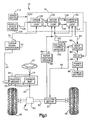
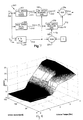
- an electric assist steering system 10 includes a steering wheel 12 connected to an input shaft 14.
- the input shaft (14) is operatively connected to an output shaft 20 through a torsion bar 16.
- the torsion bar 16 twists in response to applied steering torque thereby permitting relative rotation between the input shaft 14 and the output shaft 20. Stops (not shown) limit the amount of relative rotation between the input and output shafts 14 and 20 in a manner known in the art.
- the torsion bar 16 has a spring constant, referred to herein as K t .
- K t The amount of applied steering torque as a function of relative rotational movement between the input shaft 14 and the output shaft 20 in response to applied steering torque is a function of K t .
- the spring constant K t may be expressed in units of Newton-meters (N•M) or in-lbs. per degree of rotation between the input shaft 14 and the output shaft 20.
- a position sensor 22 is operatively connected to the input shaft 14 and to the output shaft 20.
- the position sensor 22 in combination with the torsion bar 16 forms a torque sensor 30.
- the position sensor 22 determines the relative rotational position between the input shaft 14 and the output shaft 20.
- the torque sensor 30 provides an applied torque signal ⁇ app , indicated at 24, to a torque signal processor 32.
- the applied torque signal ⁇ app is indicative of the relative rotational position between the input shaft 14 and the output shaft 20.
- the torque signal processor 32 monitors the angle between the input shaft 14 and the output shaft 20 via the applied torque signal ⁇ app and, given the spring constant K t of the torsion bar 16, provides a signal, shown at 34, indicative of the applied steering torque ⁇ s .
- the output shaft 20 is connected to a pinion gear 40.
- the pinion gear 40 as is well known in the art, has helical teeth that engage or mesh with straight cut teeth on a steering rack or linear steering number 42.
- the pinion gear 40 in combination with the gear teeth on the steering rack 42 form a rack and pinion gear set 44.
- the steering rack 42 is operatively coupled to the vehicle's steerable wheels 46 via steering linkage (not shown) in a known manner.
- the rack and pinion gear set 44 converts the rotary motion of the steering wheel 12 into linear motion of the steering rack 42.
- the steerable wheels 46 pivot about their associated steering axes.
- an electric assist motor 50 is operatively connected to the steering rack 42 through a ball-nut assembly (not shown) in a known manner or other desired gearing arrangement (such as a worm and wheel, bevel gear or belt driven system).
- a ball-nut assembly not shown
- gearing arrangement such as a worm and wheel, bevel gear or belt driven system.
- the electric assist motor 50 may have an alternative connection to the steering members for the purpose of providing steering assist.
- the electric assist motor 50 could be operatively connected to the output shaft 20, to a separate pinion drive arrangement, etc. When energized, the electric assist motor 50 provides power assist to aid in the rotation of the vehicle steering wheel 12 by the vehicle operator.
- the electric motor 50 of the example embodiment may be of any known type suitable for use in the electric assist steering system 10.
- the electric. motor 50 may be a variable reluctance ("VR") motor, a permanent magnet alternating current (“PMAC”) motor or a brushless direct current (“BLDC”) motor.
- the electric motor 50 is described herein as having the specific purpose of providing power assist in the electric assist steering system 10.
- the present invention is equally applicable to other motor configurations and other motor purposes such as providing mechanical power for machine tools.
- an electric assist motor in an electric assist steering system 10 is well known in the art. Basically, the stator poles are energized to achieve a desired amount of motor torque in a desired rotational direction. The direction of motor rotation is controlled in response to the sequence in which the stator coils are energized in certain motor types and the direction of current flow in other motor types. The torque produced by the motor is controlled by the amount of current through the stator coils.
- the electric assist motor 50 is a PMAC motor.
- the motor rotor When the electric motor 50 is energized, the motor rotor turns which, in turn, rotates the nut portion of the ball-nut drive arrangement to which the rotor is connected. When the nut rotates, the balls transfer a linear force to the steering rack 42. The direction of movement of the steering rack 50 is dependent upon the direction of rotation of the electric motor 50.
- a rotor position sensor 60 is operatively connected to the motor 50 and senses the position of the rotor relative to the stator.
- the position sensor 60 provides a rotor position signal ⁇ , indicated at 62, having a value indicating that relative position between the rotor and the stator.
- the structure and operation of a rotor position sensor is known in the art and, therefore, is not described herein in detail. It is necessary to know the position of the rotor relative to the stator to achieve the desired rotational direction and output torque of the electric motor 50.
- the electric assist steering system 10 includes an electronic control unit (ECU) 70.
- the ECU 70 is preferably a microcomputer having suitable memory. It will be appreciated that the ECU 70 may have other suitable configurations.
- the ECU 70 is programmed with control algorithms that are operative to control the electric motor 50 in a predetermined manner in response to sensed parameters.
- the ECU 70 is operatively connected to a drive circuit 80.
- the drive circuit 80 is operatively connected to a power supply 84 via a relay 82.
- the power supply 84 is operatively connected to a vehicle battery 86 and regulates electrical power supplied to the drive circuit 80.
- the ECU 70 provides a voltage control output signal ⁇ out , indicated at 90, to the drive circuit 80.
- the voltage control output signal ⁇ out is indicative of the voltage to be supplied to each phase of the electric motor 50, as determined by the control algorithms programmed in the ECU 70 and described below in detail.
- the drive circuit 80 include FETs or other suitable forms of controllable solid state switches that are operative to provide motor current , indicated at 92, to the phases of the electric motor 50. Motor current for each phase of the electric motor 50 is controlled by PWM of the FETs in accordance with the voltage control output signal ⁇ out .
- a voltage/current monitoring device 100 monitors the motor current provided to the electric motor 50 and provides a measured motor current signal of each phase to the ECU 70. These measured motor current signals are indicated at 102.
- the rotor position sensor 60 and the torque signal processor 32 provide the rotor position ⁇ signal and the sensed torque ⁇ s signal, respectively, to the ECU 70.
- a vehicle speed sensor 104 provides a vehicle speed signal ⁇ , indicated at 106, to the ECU 70.
- Other inputs, indicated generally at 114, may also be provided to the ECU 70 for control, safety, or system monitoring purposes.
- the control algorithms stored in the ECU 70 comprise a torque control loop 120, a motor control loop 130, and a current control loop 140.
- the torque control loop 120 is operative to determine a requested torque command signal ⁇ cmd , indicated at 126.
- the torque command signal ⁇ cmd is indicative of the amount of steering assist torque required from the electric motor 50, based at least partially on the sensed steering applied torque ⁇ s and the sensed vehicle speed ⁇ .
- the torque control loop 120 provides the torque command signal ⁇ cmd to the motor control loop 130.
- the motor control loop 130 is operative to determine a motor current command , indicated at 132, and a dq current advance angle ⁇ , indicated at 134.
- a dq current control loop is used to control the current in the electric motor 50.
- the current command signal indicates the amount of current to be supplied to the electric motor 50.
- the dq current advance angle ⁇ indicates rotational angle of the motor current with respect to the q-axis to which the motor is to be commanded.
- the dq-current advance angle ⁇ is determined as a function of motor speed and is non-zero only for high motor speeds.
- the current command signal and the dq current advance angle ⁇ are determined based on the torque command ⁇ cmd and the sensed rotor velocity ⁇ .
- the measured motor current and the sensed rotor position ⁇ are provided to the motor control loop 130 for feedback and monitoring purposes.
- the motor control loop 130 provides the motor current command and the dq current advance angle ⁇ to the current control loop 140.
- the current control loop 140 is operative to determine the voltage output signal ⁇ out .
- the voltage output signal ⁇ out is indicative of the voltage to be supplied to each phase of the PMAC electric assist motor 50.
- the voltage output signal ⁇ out is determined based at least partially on the current command , the dq current advance angle ⁇ , and the sensed rotor position ⁇ .
- the voltage output signal ⁇ out is formatted to control PWM of the FETs in the drive circuit 80 such that appropriate amounts of motor current are provided to each phase of the electric motor 50.
- the measured motor current is provided to the motor control loop 130 and the current control loop 140.
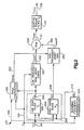
- the torque control loop 120 is illustrated in Fig. 2. In this explanation, some of the functions performed by the ECU 70 are interchangeably referred to as functions or circuits.
- the sensed torque signal ⁇ B is provided to a blending filter 200 of the torque control loop 120.
- the blending filter 200 is designed by measuring the open loop transfer function G p as a function of vehicle speed.
- the blending filter 200 is designed to meet stability and performance specifications for all vehicle speeds ⁇ .
- the blending filter 200 is also designed to meet desired performance objectives, gain stability margins, and phase stability margins.
- the blending filter 200 includes a low pass filter (G L ) 202 and a high pass filter (G H ) 204.
- the low and high pass filters 202 and 204 are designed such that summation of the two filters is equal to one for all frequencies.
- the low pass filter 202 allows all of the sensed torque signal ⁇ s with frequency content below a blending frequency ⁇ b to pass through while rejecting all high frequency content of the signal.
- the high pass filter 204 allows all of the sensed torque signal ⁇ s with frequency content above the blending frequency ⁇ b to pass through while rejecting all low frequency content of the signal.
- the blending filter frequency ⁇ b is determined as a function of vehicle speed ⁇ by a blending filter determination function 210. The determination of ⁇ b may be accomplished using a look-up table in the ECU 70 or may be accomplished by performing a calculation in accordance with a predetermined equation.
- the low pass filter 202 is chosen to be a first order filter with a pole at the blending frequency ⁇ b .
- the sensed torque signal ⁇ o input to the blending filters is passed through the low pass filter to obtain the low-passed torque signal ⁇ sL .
- the high-passed torque signal is the sensed torque ⁇ s minus the low-passed torque signal ⁇ sL .
- the low pass filter 202 provides a low-passed torque signal ⁇ sL , indicated at 206, to a low frequency dual assist curve circuit 220.
- the dual assist curve circuit 220 provides a low frequency assist torque signal ⁇ assistLF having a value functionally related to the low-passed torque signal ⁇ sL and the sensed vehicle speed v.
- the dual assist curve function 220 is illustrated in Fig. 3.
- the dual assist curve circuit 220 is illustrative of one method for determining the low frequency assist torque ⁇ assistLF based on the low-passed torque signal ⁇ SL . Those skilled in the art will appreciate that there are other methods for determining the low frequency assist torque ⁇ assistLF based on the low-passed torque signal ⁇ sL .
- the low-passed torque signal ⁇ sL is provided to a low-speed assist curve function 230, which provides a low-speed assist torque signal ⁇ assistLS , indicated at 234.
- the low-speed assist torque signal ⁇ assistLS represents an assist torque value intended for low or zero speed situations, such as vehicle parking.
- the low-speed assist torque signal ⁇ assistLS is determined as a function of the low-passed torque signal ⁇ sL , which may be accomplished using a look-up table stored in the ECU 70 or may be accomplished by performing a calculation in accordance with a predetermined equation.
- the low speed assist curve typically has a deadband, wherein no assist is provided until the steering wheel torque exceeds a predetermined level. The deadband is required so that the steering wheel returns to center when released by the driver.
- the low-passed torque signal ⁇ sL is also provided to a high-speed assist curve function 232, which provides a high-speed assist torque signal ⁇ assistHS , indicated at 236.
- the high-speed assist torque signal ⁇ assistHS represents an assist torque value intended for high speed vehicle operation, such as highway driving.
- the high-speed assist torque signal ⁇ assistHS is determined as a function of the low-passed torque signal ⁇ sL , which may be accomplished using a look-up table stored in the ECU 70 or may be accomplished by performing a calculation in accordance with a predetermined equation.
- the vehicle speed signal ⁇ is provided to a blending gain curve circuit 240, which provides a speed proportional blending term or value S p , indicated at 242.
- the speed proportional blending term Sp varies between zero and one as a function of vehicle speed.
- speed proportional blending term S p varies between zero at high or maximum vehicle speeds and one at low or zero vehicle speed.
- the speed proportional blending term S p is used to blend the low-speed assist torque ⁇ assistLS with the high-speed assist torque ⁇ assistHS .
- the speed proportional blending term S p and the low-speed assist torque ⁇ assistLS are provided to a low-speed blending gain circuit 250, which provides a blended low-speed assist torque signal ⁇ assistLS ', indicated at 252.
- the low-speed blending gain circuit 250 multiplies the low-speed assist torque ⁇ assistLS by a low-speed blending gain value which is equal to the speed proportional blending term S p .
- the speed proportional blending term S p is subtracted from one at a summation circuit 254 to determine a high-speed blending gain value 1-S p , indicated at 256.
- the high-speed blending gain value 1-S p and the high-speed assist torque ⁇ assistHS are provided to a high-speed blending gain circuit 260, which provides a blended high-speed assist torque signal ⁇ assistHS ', indicated at 262.
- the high-speed blending gain circuit 260 multiplies the high-speed assist torque ⁇ assistHS by the high-speed blending gain value 1-S p .
- the sum of the low and high-speed blending gain values are thus always equal to one.
- the blended low-speed assist torque signal ⁇ assistLS ' and the blended high-speed assist torque signal ⁇ assistHS ' are summed at a summing circuit 264 to provide a low frequency assist torque signal ⁇ assistLF , indicated at 266.
- the high-passed torque signal ⁇ SH is provided to a high frequency assist gain circuit 280, which determines a high frequency assist signal ⁇ assistHF , indicated at 282.
- the high frequency assist signal ⁇ assistHF is added to the low frequency assist torque signal ⁇ assistLF at a summing circuit 284 to determine a torque assist signal ⁇ assist , indicated at: 122.
- the torque assist signal ⁇ assist may be filtered through an adaptive torque filter G f , indicated at 124, to determine the motor command signal ⁇ cmd .
- An example of such an adaptive torque filter G f is described in U.S. Patent No. 5,473,231, issued to McLaughlin et al., to which reference is hereby directed.
- the high frequency assist signal ⁇ assistHF is determined as the product of the high-passed torque signal ⁇ sH and a high frequency assist gain K max .
- the high frequency assist gain K max helps determine the bandwidth of the electric assist steering system 10. At high vehicle speeds, it is desirable to incorporate a relatively high value for the high frequency gain K max in order to provide good off-center tracking. It is, however, also desirable, at high vehicle speeds, to incorporate a relatively low value for the high frequency gain K max in order to provide good on-center feel- According to the present invention, the high frequency gain K max is determined according to an algorithm that provides good off-center tracking and good on-center feel at high vehicle speeds.
- the high frequency assist gain K max is determined at a K max computation function 290.
- the high frequency assist gain K max is determined as a function of the vehicle speed ⁇ and the sensed torque signal ⁇ s .
- the high frequency assist gain K max is determined as a function of the vehicle speed ⁇ and the low-passed torque signal ⁇ sL .
- the high frequency assist gain K max could, however, be determined as a function of the vehicle speed ⁇ and the sensed torque signal ⁇ s , as illustrated by the dashed line labeled 294 in Fig. 2. Of course, in this instance, it would not be necessary to provide the low-passed torque signal ⁇ sL to the K max computation circuit 290.
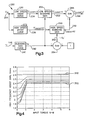
- the graph of Fig. 4 illustrates an example by which the high frequency assist gain K max is determined as a function of the vehicle speed ⁇ and the input torque. It will be appreciated that this graph may change, depending on the particular vehicle platform and/or desired steering response characteristics.
- the input torque may be the sensed torque signal ⁇ s or the low-passed torque signal ⁇ sL .
- the high frequency assist gain K max for low or zero speed is defined by the curve indicated at 300.
- the high frequency assist gain K max for high or maximum speed is defined by the curve indicated at 302.
- the curves spaced between the low-speed and high-speed high frequency assist curves 300 and 302 indicate the high frequency assist gain K max at predetermined incremental variations in vehicle speed.
- the high frequency assist gain K max is constant, i.e., is the same regardless of the amount of input torque.
- the low-speed K max curve 300 could, however, be adapted to provide a high frequency assist gain K max that varies with the amount of input torque.
- the high frequency assist gain K max increases depending on the vehicle speed and the input torque, i.e., the low-passed torque ⁇ sL .
- the high frequency assist gain K max increases from a minimum value, depending on vehicle speed, as the input torque increases from zero N•M.
- the high frequency assist gain K max increases at a generally low rate or slope from zero N•M. to about 0.3 N•M.
- the high frequency assist gain K max increases at a higher rate or slope from 0.3 N•M. to just over 1.0 N•M. At about just over 1.0 N•M., the high frequency assist gain K max remains constant regardless of the amount of input torque.
- the K max computation circuit 290 determines the high frequency assist gain K max in accordance with the curves illustrated in Fig. 4. The computation may be accomplished using a look-up table stored in the ECU 70. Interpolation techniques may be used to determine the high frequency assist gain K max when the vehicle speed ⁇ is between the predetermined speeds defined by the two closest speed curves. The K max computation circuit 290 alternatively could determine the high frequency assist gain K max by performing a calculation in accordance with a predetermined equation selected in accordance with the K max curves in Fig. 4.
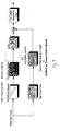
- the K max computation circuit 290 performs a dual curve blending algorithm, similar to the algorithm incorporated in the low frequency dual assist curve circuit 220 (Fig. 3), to determine the high frequency assist gain K max .
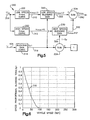
- the low-speed K max curve 300 (Fig. 4) is blended with the high-speed K max curve 302 to determine the high frequency assist gain K max . This is illustrated in Fig. 5.
- the low-passed torque signal ⁇ sL 206 is provided to the low-speed K max curve 300, which provides a low-speed high frequency assist gain K maxLS , indicated at 310.
- the low-speed high frequency assist gain K maxLS represents a high frequency assist gain value intended for low or zero vehicle speed situations, such as vehicle parking.
- the low-speed high frequency assist gain K maxLS is determined as a function of the low-passed torque signal ⁇ sL , which may be accomplished using a look-up table stored in the ECU 70 or may be accomplished by performing a calculation in accordance with a predetermined equation.
- the low-passed torque signal T sL is also provided to the high-speed K max curve 302, which provides a high-speed high frequency assist gain K maxHS , indicated at 312.
- the high-speed high frequency assist gain K maxHS represents a high frequency assist gain intended for high speed vehicle operation, such as highway driving.
- the high-speed high frequency assist gain K maxHS is determined as a function of the low-passed torque signal ⁇ sL , which may be accomplished using a look-up table stored in the ECU 70 or may be accomplished by performing a calculation in accordance with a predetermined equation.
- the vehicle speed signal ⁇ 106 is provided to a blending gain curve circuit 314, which provides a speed proportional blending term or value S p1 (also referred to as a foldback gain), indicated at 316.
- S p1 also referred to as a foldback gain
- the speed proportional blending term S p1 varies between zero and one as a function of vehicle speed v, as illustrated by the graph of Fig. 6. As shown in Fig. 6, in the example embodiment, speed proportional blending term S p1 , indicated at 316, varies between zero at high vehicle speeds and one at zero vehicle speed.
- the speed proportional blending term S p1 is used to blend the low-speed high frequency assist gain K maxLS with the high-speed high frequency assist gain K maxHS .
- the speed proportional blending term S p1 and the low-speed high frequency assist gain K maxLS are provided to a low-speed blending gain function 320, which provides a blended low-speed high frequency assist gain K maxLS ', indicated at 322.
- the low-speed blending gain circuit 320 multiplies the low-speed high frequency assist gain K maxLS by a low-speed blending gain value which is equal to the speed proportional blending term S p1 .
- the speed proportional blending term S p1 is subtracted from one at a summation circuit 324 to determine a high-speed blending gain value 1-S p1 , indicated at 326.
- the high-speed blending gain value 1-S p1 and the high-speed high frequency assist gain K maxHS are pxovided to a high-speed blending gain circuit 330, which provides a blended high-speed high frequency assist gain K maxHS ', indicated at 332.
- the high-speed blending gain circuit 330 multiplies the high-speed high frequency assist gain K maxHS by the high-speed blending gain value 1-S p1 .
- the sum of the low and high-speed blending gain values are thus always equal to one.
- K max S p 1 ⁇ K max LS + (1 - S p 1 ) ⁇ K max HS ; and thus provides a smooth interpolation of the low and high-speed high frequency assist gain values K maxLS and K maxHS as vehicle speed ⁇ changes.
- the high frequency assist gain K max is determined based on both vehicle speed ⁇ and input torque ⁇ sL . As illustrated by the K max curves in Fig. 4 and Fig. 8, in general, the high frequency assist gain K max increases as vehicle speed ⁇ decreases. Also, at any given speed, the high frequency assist gain K max varies as a function of input torque ⁇ sL . In general, for the particular K max curves illustrated in Fig. 4, at any given speed (except zero speed where K max is constant), the high frequency assist gain K max is lower for low input torque values and higher for high input torque values. Therefore, at high vehicle speeds ⁇ , the high frequency assist gain K max is adapted to provide good off-center tracking as well as good on-center feel.
- the torque control loop 120 is dominated by the high frequency assist gain portion 280 of the loop. Stability is easily analyzed and tested because the system behaves like a linear system near the zero crossover frequency. Since the blending frequency ⁇ b and the high frequency assist gain K max are both functions of vehicle speed ⁇ , the system bandwidth of the electric assist steering system 10 can be controlled as a function of vehicle speed. This can be done by modifying the high frequency assist gain K max via the speed proportional blending term S p1 . The bandwidth decreases as the high frequency assist gain K max decreases. Therefore, the high frequency portion of the torque control loop 120 defines the transient response and stability characteristics of the electric assist steering system 10.
- the torque control loop 120 is dominated by the low frequency dual assist curve portion 220 of the loop. This low frequency portion of the torque control loop 120 determines how the electric assist steering system 10 feels to the driver for slow, steady inputs.
- the dual assist curves may be tuned such that the electric assist steering system 10 provides a desired steering feel.
- the amount of assist torque provided by the electric assist steering system 10 increases gradually as input torque ( ⁇ meas ) increases away from the steering wheel torque dead-band.
- the local gain of the electric assist steering system 10 is generally very low, i.e., it takes a large change in input torque to produce a small change in steering assist torque.
- the high frequency assist gain portion 280 of the torque control loop 120 Without the high frequency assist gain portion 280 of the torque control loop 120, the overall system bandwidth would be reduced at low-input torque and the electric assist steering system 10 would feel sluggish.
- the inclusion of the high frequency assist gain portion 280 of the torque control loop 120 allows the system bandwidth to be selectable and causes the system to respond smoothly coming off of the deadband.
- the non-linear low frequency dual assist curve portion 220 of the torque control loop 120 is a slowly varying phenomena when compared to the dynamics of the steering system. In essence, the non-linear low frequency portion is dynamically decoupled from the linear high frequency assist gain portion 280 of the torque control loop 120.
- the electric assist steering system 10 thus behaves in a non-linear fashion for low frequency inputs, and in a linear fashion for high frequency inputs.
- DAC dual assist curve
- speed pro speed dependent ratio
- the "speed pro" 314 is used to determine the preponderance of each of the low and high speed curves at a given vehicle speed.
- the "speed pro” is provided by the blending gain curve 314 which is responsive to vehicle speed alone to provide a speed proportional blending term S p1 on line 316.
- the speed pro based on vehicle speed has the limitation in practice of slightly limiting the tuning freedom of the system, namely the balance between the desired characteristic wherein good on-centre feel requires a low value of high frequency gain K max whereas good off-centre feel needs the high frequency gain K max to have a high value.
- the speed pro/blending gain curve of Fig. 5 is replaced by a two-dimensional look-up table which has two inputs, namely vehicle speed and low frequency torque, and an output K max .
- the latter arrangement is shown in Fig. 7 wherein parts which have the same function as in Fig. 5 are given the same reference numerals as in Fig. 5.
- the embodiment of Fig. 7 includes a two-dimensional map 350 having an input from line 106 carrying a signal ⁇ corresponding to the vehicle speed and an input from a line 206 carrying the low frequency torque signal T SL and an output K max 292.
- the K max computation circuit 290 performs a two-dimensional linearly-interpolated map look-up function to determine the high frequency gain K max .
- the two-dimensional look-up table 350 is stored in the ECU 70.
- the high frequency assist algorithm 280 generates the high frequency assist torque signal ⁇ assist HF 282 by forming the product of K max 292 and the high-pass filtered torque signal ⁇ SH 208.
- An example of a possible 2D map 350 is shown in Fig. 8.
- FIG. 9 A block diagram of the overall system incorporating the modifications of Figs 7 and 8 is shown in Fig. 9.
Landscapes
- Engineering & Computer Science (AREA)
- Chemical & Material Sciences (AREA)
- Combustion & Propulsion (AREA)
- Transportation (AREA)
- Mechanical Engineering (AREA)
- Steering Control In Accordance With Driving Conditions (AREA)
- Power Steering Mechanism (AREA)
Applications Claiming Priority (2)
| Application Number | Priority Date | Filing Date | Title |
|---|---|---|---|
| GB0401965 | 2004-01-30 | ||
| GBGB0401965.9A GB0401965D0 (en) | 2004-01-30 | 2004-01-30 | Method and apparatus for controlling an electric assist motor using a modified blending filter |
Publications (2)
| Publication Number | Publication Date |
|---|---|
| EP1559633A1 true EP1559633A1 (fr) | 2005-08-03 |
| EP1559633B1 EP1559633B1 (fr) | 2007-09-05 |
Family
ID=31971678
Family Applications (1)
| Application Number | Title | Priority Date | Filing Date |
|---|---|---|---|
| EP05250191A Expired - Lifetime EP1559633B1 (fr) | 2004-01-30 | 2005-01-14 | Procédé et dispositif de contrôle d'un moteur d' assistance électrique en utilisant un filtre de mélangeage modifié |
Country Status (6)
| Country | Link |
|---|---|
| US (2) | US20050251311A1 (fr) |
| EP (1) | EP1559633B1 (fr) |
| JP (1) | JP4303689B2 (fr) |
| DE (1) | DE602005002275T2 (fr) |
| ES (1) | ES2289662T3 (fr) |
| GB (1) | GB0401965D0 (fr) |
Cited By (1)
| Publication number | Priority date | Publication date | Assignee | Title |
|---|---|---|---|---|
| EP1932745A3 (fr) * | 2006-12-15 | 2008-09-03 | Delphi Technologies, Inc. | Procédé et dispositif pour compenser le tirage d'une direction vers un côté |
Families Citing this family (22)
| Publication number | Priority date | Publication date | Assignee | Title |
|---|---|---|---|---|
| US20060184300A1 (en) * | 2005-02-11 | 2006-08-17 | Schubert Peter J | Vehicle rollover detection method based on differential z-axis acceleration |
| RU2278797C1 (ru) * | 2005-08-19 | 2006-06-27 | Открытое акционерное общество "Калужский завод электронных изделий" | Электромеханический усилитель руля автомобиля и электродвигатель для усилителя руля |
| US20070144814A1 (en) * | 2005-12-22 | 2007-06-28 | Arnold Steven D | Torque sensor based steering response |
| JP4637933B2 (ja) * | 2008-05-29 | 2011-02-23 | 三菱電機株式会社 | 電動パワーステアリング装置 |
| JP5235536B2 (ja) * | 2008-07-03 | 2013-07-10 | 三菱電機株式会社 | 電動パワーステアリング制御装置 |
| JP2010100217A (ja) * | 2008-10-24 | 2010-05-06 | Jtekt Corp | 電動パワーステアリング装置 |
| US8335611B2 (en) * | 2008-12-02 | 2012-12-18 | GM Global Technology Operations LLC | Methods and systems for controlling motor current in steering systems of vehicles equipped with electric steering assist |
| US8473158B2 (en) * | 2009-08-26 | 2013-06-25 | Steering Solutions Ip Holding Corporation | Stability-based steering control methods and systems |
| WO2011052470A1 (fr) * | 2009-10-30 | 2011-05-05 | 三菱電機株式会社 | Dispositif de commande de direction assistée électrique |
| KR101680898B1 (ko) * | 2010-05-20 | 2016-11-29 | 엘지이노텍 주식회사 | 스티어링 시스템의 토크 센서 |
| DE102011016052A1 (de) * | 2011-04-05 | 2012-10-11 | Volkswagen Ag | Verfahren und Vorrichtung zur Bestimmung eines Soll-Unterstützungsmoments in einem Lenksystem und Lenksystem |
| US8498783B2 (en) * | 2011-07-28 | 2013-07-30 | Trw Automotive U.S. Llc | Method of controlling a vehicle steering apparatus |
| US8886408B2 (en) | 2012-01-30 | 2014-11-11 | Honda Motor Co., Ltd. | Vehicle steering control system and method |
| US9966890B2 (en) * | 2016-02-16 | 2018-05-08 | Steering Solutions Ip Holding Corporation | Detection of offset errors in phase current measurement for motor control system |
| US9873450B2 (en) * | 2016-02-16 | 2018-01-23 | Steering Solutions Ip Holding Corporation | Detection of offset errors in phase current measurement for motor control system |
| JP6584658B2 (ja) * | 2016-05-24 | 2019-10-02 | 三菱電機株式会社 | 電動パワーステアリング装置 |
| KR101858180B1 (ko) | 2017-07-04 | 2018-06-27 | 이래에이엠에스 주식회사 | 전동 어시스트 조향 시스템의 모터 제어 방법 및 장치 |
| KR101954762B1 (ko) | 2018-01-02 | 2019-05-23 | 이래에이엠에스 주식회사 | 전동 어시스트 조향 시스템의 모터 제어 방법 및 장치 |
| KR101998368B1 (ko) | 2018-01-03 | 2019-07-09 | 이래에이엠에스 주식회사 | 전동 어시스트 조향 시스템의 모터 제어 방법 및 장치 |
| KR102018153B1 (ko) | 2018-01-04 | 2019-09-04 | 이래에이엠에스 주식회사 | 전동 어시스트 조향 시스템의 모터 제어 방법 및 장치 |
| US11117612B2 (en) * | 2018-03-09 | 2021-09-14 | Steering Solutions Ip Holding Corporation | Dither noise management in electric power steering systems |
| US11511795B2 (en) * | 2018-10-11 | 2022-11-29 | Steering Solutions Ip Holding Corporation | Dither noise management in electric power steering systems |
Citations (4)
| Publication number | Priority date | Publication date | Assignee | Title |
|---|---|---|---|---|
| EP0842841A1 (fr) * | 1996-11-19 | 1998-05-20 | General Motors Corporation | Commande pour direction assistée électrique |
| EP0943527A2 (fr) * | 1998-03-20 | 1999-09-22 | Trw Inc. | Système de direction assistée électrique muni d'un moyen de commande de courant de moteur amélioré avec filtre coupe-bande |
| WO2001012492A1 (fr) * | 1999-08-17 | 2001-02-22 | Trw Lucas Varity Electric Steering Ltd. | Procede et appareil de commande d'un systeme de direction assistee electrique utilisant un filtre adaptatif combinant pour signal de couple |
| WO2004017487A2 (fr) * | 2002-08-14 | 2004-02-26 | Trw Automotive U.S. Llc | Procede et appareil pour controler un moteur assiste electriquement au moyen d'un filtre de melangeage modifie |
Family Cites Families (17)
| Publication number | Priority date | Publication date | Assignee | Title |
|---|---|---|---|---|
| US4415054A (en) * | 1982-08-05 | 1983-11-15 | Trw Inc. | Steering gear |
| JP2592610B2 (ja) * | 1987-06-08 | 1997-03-19 | 富士重工業株式会社 | 電動式パワーステアリング装置のモータ制御装置 |
| US4961038A (en) * | 1989-10-16 | 1990-10-02 | General Electric Company | Torque estimator for switched reluctance machines |
| US5257828A (en) * | 1992-06-03 | 1993-11-02 | Trw Inc. | Method and apparatus for controlling damping in an electric assist steering system for vehicle yaw rate control |
| US5568389A (en) * | 1994-03-11 | 1996-10-22 | Trw Inc. | Method and apparatus for controlling an electric assist steering system |
| JPH07264712A (ja) * | 1994-03-18 | 1995-10-13 | Hitachi Ltd | 電気車の制御装及び制御方法 |
| US5473231A (en) * | 1994-05-11 | 1995-12-05 | Trw Inc. | Method and apparatus for controlling an electric assist steering system using an adaptive torque filter |
| US5517415A (en) * | 1994-10-26 | 1996-05-14 | Trw Inc. | Method and apparatus for detecting a motor stall condition in an electric assist steering system |
| US5623409A (en) * | 1994-10-31 | 1997-04-22 | Trw Inc. | Method and apparatus for non-linear damping of an electric assist steering system for vehicle yaw rate control |
| US5475289A (en) * | 1994-11-04 | 1995-12-12 | Trw Inc. | Method and apparatus for controlling an electric assist steering system using two-dimensional interpolation for current commands |
| JP3493806B2 (ja) * | 1995-04-21 | 2004-02-03 | 日本精工株式会社 | 電動パワ−ステアリング装置の制御装置 |
| US5704446A (en) * | 1995-10-02 | 1998-01-06 | General Motors Corporation | Electric power steering control |
| US5743351A (en) * | 1996-05-29 | 1998-04-28 | Trw Inc. | Method and apparatus for controlling an electric assist steering sysem by linearizing system input-output torque gain |
| US6046560A (en) * | 1998-03-20 | 2000-04-04 | Trw Inc. | Electric assist steering system having an improved motor current controller with gain scheduler |
| US6965820B2 (en) * | 2001-09-18 | 2005-11-15 | Delphi Technologies, Inc. | Robust steering-pull torque compensation |
| US20050182542A1 (en) * | 2002-09-06 | 2005-08-18 | Volkswagen Aktiengesellschaft | Device and procedure for a steering support for vehicles with electromechanical steering system |
| US6863150B1 (en) * | 2003-09-25 | 2005-03-08 | Mitsubishi Denki Kabushiki Kaisha | Electric power steering control apparatus |
-
2004
- 2004-01-30 GB GBGB0401965.9A patent/GB0401965D0/en not_active Ceased
-
2005
- 2005-01-14 ES ES05250191T patent/ES2289662T3/es not_active Expired - Lifetime
- 2005-01-14 EP EP05250191A patent/EP1559633B1/fr not_active Expired - Lifetime
- 2005-01-14 DE DE602005002275T patent/DE602005002275T2/de not_active Expired - Lifetime
- 2005-01-28 JP JP2005021566A patent/JP4303689B2/ja not_active Expired - Fee Related
- 2005-01-28 US US11/046,182 patent/US20050251311A1/en not_active Abandoned
-
2010
- 2010-01-28 US US12/695,702 patent/US20100198461A1/en not_active Abandoned
Patent Citations (4)
| Publication number | Priority date | Publication date | Assignee | Title |
|---|---|---|---|---|
| EP0842841A1 (fr) * | 1996-11-19 | 1998-05-20 | General Motors Corporation | Commande pour direction assistée électrique |
| EP0943527A2 (fr) * | 1998-03-20 | 1999-09-22 | Trw Inc. | Système de direction assistée électrique muni d'un moyen de commande de courant de moteur amélioré avec filtre coupe-bande |
| WO2001012492A1 (fr) * | 1999-08-17 | 2001-02-22 | Trw Lucas Varity Electric Steering Ltd. | Procede et appareil de commande d'un systeme de direction assistee electrique utilisant un filtre adaptatif combinant pour signal de couple |
| WO2004017487A2 (fr) * | 2002-08-14 | 2004-02-26 | Trw Automotive U.S. Llc | Procede et appareil pour controler un moteur assiste electriquement au moyen d'un filtre de melangeage modifie |
Cited By (3)
| Publication number | Priority date | Publication date | Assignee | Title |
|---|---|---|---|---|
| EP1932745A3 (fr) * | 2006-12-15 | 2008-09-03 | Delphi Technologies, Inc. | Procédé et dispositif pour compenser le tirage d'une direction vers un côté |
| EP2070803A1 (fr) * | 2006-12-15 | 2009-06-17 | Delphi Technologies, Inc. | Procédé, système et appareil pour la fourniture d'une compensation améliorée du déséquilibre directionnel |
| US8903606B2 (en) | 2006-12-15 | 2014-12-02 | Steering Solutiions IP Holding Corporation | Method, system, and apparatus for providing enhanced steering pull compensation |
Also Published As
| Publication number | Publication date |
|---|---|
| GB0401965D0 (en) | 2004-03-03 |
| JP4303689B2 (ja) | 2009-07-29 |
| DE602005002275T2 (de) | 2008-05-29 |
| US20050251311A1 (en) | 2005-11-10 |
| EP1559633B1 (fr) | 2007-09-05 |
| JP2005212778A (ja) | 2005-08-11 |
| ES2289662T3 (es) | 2008-02-01 |
| DE602005002275D1 (de) | 2007-10-18 |
| US20100198461A1 (en) | 2010-08-05 |
Similar Documents
| Publication | Publication Date | Title |
|---|---|---|
| US6789641B2 (en) | Method and apparatus for controlling an electric assist motor using a modified blending filter | |
| US20100198461A1 (en) | Method and apparatus for controlling an electric assist motor using a modified blending filter | |
| US6631781B2 (en) | Method and apparatus for controlling an electric powered assisted steering system using an adaptive blending torque filter | |
| US6422335B1 (en) | Method and apparatus for controlling steering feel with diagnostics | |
| US5504403A (en) | Method and apparatus for controlling an electric assist steering system using an adaptive blending torque filter | |
| EP1884447A1 (fr) | Amortissement actif dépendant du quadrant pour direction assistée électrique | |
| EP1052161A2 (fr) | Système de direction pour véhicules automobiles | |
| US6671597B2 (en) | Electric power steering controller | |
| EP1211160A1 (fr) | Système d'assistance électrique de direction | |
| EP0842841B1 (fr) | Commande pour direction assistée électrique | |
| EP0683086B1 (fr) | Procédé et appareil pour contrôler un système de direction assistée électrique avec un filtre transitionnel adaptif du couple | |
| EP1316494B1 (fr) | Procédé et dispositif pour commander la sensation de direction avec diagnostics | |
| KR101858180B1 (ko) | 전동 어시스트 조향 시스템의 모터 제어 방법 및 장치 | |
| EP0842840A1 (fr) | Commande pour direction assistée électrique | |
| CN1516659A (zh) | 电动机驱动的伺服转向单元 | |
| JP6252062B2 (ja) | ステアリング制御装置 | |
| EP4088990B1 (fr) | Dispositif de commande de braquage | |
| JP2838053B2 (ja) | 適応混合トルク・フィルタを用いた電気アシスト・ステアリング・システムの制御方法及び装置 | |
| JP2026011533A (ja) | 制御装置、ステアリング装置、制御方法、プログラム |
Legal Events
| Date | Code | Title | Description |
|---|---|---|---|
| PUAI | Public reference made under article 153(3) epc to a published international application that has entered the european phase |
Free format text: ORIGINAL CODE: 0009012 |
|
| AK | Designated contracting states |
Kind code of ref document: A1 Designated state(s): AT BE BG CH CY CZ DE DK EE ES FI FR GB GR HU IE IS IT LI LT LU MC NL PL PT RO SE SI SK TR |
|
| AX | Request for extension of the european patent |
Extension state: AL BA HR LV MK YU |
|
| 17P | Request for examination filed |
Effective date: 20050919 |
|
| AKX | Designation fees paid |
Designated state(s): DE ES FR GB IT |
|
| GRAP | Despatch of communication of intention to grant a patent |
Free format text: ORIGINAL CODE: EPIDOSNIGR1 |
|
| GRAS | Grant fee paid |
Free format text: ORIGINAL CODE: EPIDOSNIGR3 |
|
| GRAA | (expected) grant |
Free format text: ORIGINAL CODE: 0009210 |
|
| AK | Designated contracting states |
Kind code of ref document: B1 Designated state(s): DE ES FR GB IT |
|
| REG | Reference to a national code |
Ref country code: GB Ref legal event code: FG4D |
|
| REF | Corresponds to: |
Ref document number: 602005002275 Country of ref document: DE Date of ref document: 20071018 Kind code of ref document: P |
|
| REG | Reference to a national code |
Ref country code: ES Ref legal event code: FG2A Ref document number: 2289662 Country of ref document: ES Kind code of ref document: T3 |
|
| EN | Fr: translation not filed | ||
| PLBE | No opposition filed within time limit |
Free format text: ORIGINAL CODE: 0009261 |
|
| STAA | Information on the status of an ep patent application or granted ep patent |
Free format text: STATUS: NO OPPOSITION FILED WITHIN TIME LIMIT |
|
| ET | Fr: translation filed | ||
| REG | Reference to a national code |
Ref country code: FR Ref legal event code: EERR Free format text: CORRECTION DE BOPI 08/18 - BREVETS EUROPEENS DONT LA TRADUCTION A ETE REMISE A L INPI. IL Y A LIEU DE SUPPRIMER : LA MENTION DE LA NON-REMISE. LA REMISE DE LA TRADUCTION EST PUBLIEE DANS LE PRESENT BOPI. |
|
| 26N | No opposition filed |
Effective date: 20080606 |
|
| PG25 | Lapsed in a contracting state [announced via postgrant information from national office to epo] |
Ref country code: FR Free format text: LAPSE BECAUSE OF FAILURE TO SUBMIT A TRANSLATION OF THE DESCRIPTION OR TO PAY THE FEE WITHIN THE PRESCRIBED TIME-LIMIT Effective date: 20080502 |
|
| REG | Reference to a national code |
Ref country code: GB Ref legal event code: 732E Free format text: REGISTERED BETWEEN 20130829 AND 20130904 |
|
| REG | Reference to a national code |
Ref country code: GB Ref legal event code: 732E Free format text: REGISTERED BETWEEN 20130905 AND 20130911 |
|
| REG | Reference to a national code |
Ref country code: FR Ref legal event code: PLFP Year of fee payment: 11 |
|
| REG | Reference to a national code |
Ref country code: FR Ref legal event code: PLFP Year of fee payment: 12 |
|
| REG | Reference to a national code |
Ref country code: FR Ref legal event code: PLFP Year of fee payment: 13 |
|
| REG | Reference to a national code |
Ref country code: FR Ref legal event code: PLFP Year of fee payment: 14 |
|
| PGFP | Annual fee paid to national office [announced via postgrant information from national office to epo] |
Ref country code: ES Payment date: 20180201 Year of fee payment: 14 |
|
| PGFP | Annual fee paid to national office [announced via postgrant information from national office to epo] |
Ref country code: FI Payment date: 20190122 Year of fee payment: 15 |
|
| REG | Reference to a national code |
Ref country code: ES Ref legal event code: FD2A Effective date: 20200309 |
|
| PG25 | Lapsed in a contracting state [announced via postgrant information from national office to epo] |
Ref country code: ES Free format text: LAPSE BECAUSE OF NON-PAYMENT OF DUE FEES Effective date: 20190115 |
|
| REG | Reference to a national code |
Ref country code: DE Ref legal event code: R082 Ref document number: 602005002275 Country of ref document: DE Representative=s name: HGF EUROPE LLP, DE Ref country code: DE Ref legal event code: R082 Ref document number: 602005002275 Country of ref document: DE Representative=s name: HGF EUROPE LP, DE |
|
| PG25 | Lapsed in a contracting state [announced via postgrant information from national office to epo] |
Ref country code: IT Free format text: LAPSE BECAUSE OF NON-PAYMENT OF DUE FEES Effective date: 20200114 |
|
| PGFP | Annual fee paid to national office [announced via postgrant information from national office to epo] |
Ref country code: GB Payment date: 20220127 Year of fee payment: 18 Ref country code: DE Payment date: 20220127 Year of fee payment: 18 |
|
| PGFP | Annual fee paid to national office [announced via postgrant information from national office to epo] |
Ref country code: FR Payment date: 20220125 Year of fee payment: 18 |
|
| REG | Reference to a national code |
Ref country code: DE Ref legal event code: R119 Ref document number: 602005002275 Country of ref document: DE |
|
| GBPC | Gb: european patent ceased through non-payment of renewal fee |
Effective date: 20230114 |
|
| PG25 | Lapsed in a contracting state [announced via postgrant information from national office to epo] |
Ref country code: GB Free format text: LAPSE BECAUSE OF NON-PAYMENT OF DUE FEES Effective date: 20230114 Ref country code: DE Free format text: LAPSE BECAUSE OF NON-PAYMENT OF DUE FEES Effective date: 20230801 |
|
| PG25 | Lapsed in a contracting state [announced via postgrant information from national office to epo] |
Ref country code: FR Free format text: LAPSE BECAUSE OF NON-PAYMENT OF DUE FEES Effective date: 20230131 |