EP1559800B1 - Matériau métallique composite et son procédé de préparation - Google Patents
Matériau métallique composite et son procédé de préparation Download PDFInfo
- Publication number
- EP1559800B1 EP1559800B1 EP05250437.0A EP05250437A EP1559800B1 EP 1559800 B1 EP1559800 B1 EP 1559800B1 EP 05250437 A EP05250437 A EP 05250437A EP 1559800 B1 EP1559800 B1 EP 1559800B1
- Authority
- EP
- European Patent Office
- Prior art keywords
- metal
- elastomer
- composite
- group
- filler particles
- Prior art date
- Legal status (The legal status is an assumption and is not a legal conclusion. Google has not performed a legal analysis and makes no representation as to the accuracy of the status listed.)
- Expired - Lifetime
Links
Images


Classifications
-
- B—PERFORMING OPERATIONS; TRANSPORTING
- B22—CASTING; POWDER METALLURGY
- B22D—CASTING OF METALS; CASTING OF OTHER SUBSTANCES BY THE SAME PROCESSES OR DEVICES
- B22D19/00—Casting in, on, or around objects which form part of the product
- B22D19/14—Casting in, on, or around objects which form part of the product the objects being filamentary or particulate in form
-
- B—PERFORMING OPERATIONS; TRANSPORTING
- B22—CASTING; POWDER METALLURGY
- B22F—WORKING METALLIC POWDER; MANUFACTURE OF ARTICLES FROM METALLIC POWDER; MAKING METALLIC POWDER; APPARATUS OR DEVICES SPECIALLY ADAPTED FOR METALLIC POWDER
- B22F1/00—Metallic powder; Treatment of metallic powder, e.g. to facilitate working or to improve properties
- B22F1/09—Mixtures of metallic powders
-
- B—PERFORMING OPERATIONS; TRANSPORTING
- B22—CASTING; POWDER METALLURGY
- B22F—WORKING METALLIC POWDER; MANUFACTURE OF ARTICLES FROM METALLIC POWDER; MAKING METALLIC POWDER; APPARATUS OR DEVICES SPECIALLY ADAPTED FOR METALLIC POWDER
- B22F3/00—Manufacture of workpieces or articles from metallic powder characterised by the manner of compacting or sintering; Apparatus specially adapted therefor ; Presses and furnaces
- B22F3/24—After-treatment of workpieces or articles
- B22F3/26—Impregnating
-
- C—CHEMISTRY; METALLURGY
- C22—METALLURGY; FERROUS OR NON-FERROUS ALLOYS; TREATMENT OF ALLOYS OR NON-FERROUS METALS
- C22C—ALLOYS
- C22C1/00—Making non-ferrous alloys
- C22C1/02—Making non-ferrous alloys by melting
-
- C—CHEMISTRY; METALLURGY
- C22—METALLURGY; FERROUS OR NON-FERROUS ALLOYS; TREATMENT OF ALLOYS OR NON-FERROUS METALS
- C22C—ALLOYS
- C22C1/00—Making non-ferrous alloys
- C22C1/10—Alloys containing non-metals
- C22C1/1036—Alloys containing non-metals starting from a melt
-
- C—CHEMISTRY; METALLURGY
- C22—METALLURGY; FERROUS OR NON-FERROUS ALLOYS; TREATMENT OF ALLOYS OR NON-FERROUS METALS
- C22C—ALLOYS
- C22C1/00—Making non-ferrous alloys
- C22C1/10—Alloys containing non-metals
- C22C1/1036—Alloys containing non-metals starting from a melt
- C22C1/1047—Alloys containing non-metals starting from a melt by mixing and casting liquid metal matrix composites
-
- B—PERFORMING OPERATIONS; TRANSPORTING
- B22—CASTING; POWDER METALLURGY
- B22F—WORKING METALLIC POWDER; MANUFACTURE OF ARTICLES FROM METALLIC POWDER; MAKING METALLIC POWDER; APPARATUS OR DEVICES SPECIALLY ADAPTED FOR METALLIC POWDER
- B22F2998/00—Supplementary information concerning processes or compositions relating to powder metallurgy
- B22F2998/10—Processes characterised by the sequence of their steps
-
- Y—GENERAL TAGGING OF NEW TECHNOLOGICAL DEVELOPMENTS; GENERAL TAGGING OF CROSS-SECTIONAL TECHNOLOGIES SPANNING OVER SEVERAL SECTIONS OF THE IPC; TECHNICAL SUBJECTS COVERED BY FORMER USPC CROSS-REFERENCE ART COLLECTIONS [XRACs] AND DIGESTS
- Y10—TECHNICAL SUBJECTS COVERED BY FORMER USPC
- Y10T—TECHNICAL SUBJECTS COVERED BY FORMER US CLASSIFICATION
- Y10T428/00—Stock material or miscellaneous articles
- Y10T428/12—All metal or with adjacent metals
- Y10T428/12486—Laterally noncoextensive components [e.g., embedded, etc.]
Definitions
- the present invention relates to a composite metal material and a method of producing the same.
- fillers particulate fillers (hereinafter called "filler particles”) and fibrous filler are used.
- the composite metal material using a ceramic or the like as the reinforcing material has been conventionally proposed.
- room for improvement still remains in dispersibility of the filler particles in the metal matrix.
- the compositing performance of the composite metal material is affected by wettability between the matrix metal and the reinforcing material and dispersibility of the reinforcing material in the matrix metal.
- US 5,458,181 discloses a fiber-organic composition including from about 5% to 50% by volume of uniformly dispersed, non-planar or three dimensionally random oriented inorganic fibers or whiskers, and a thermoplastic material such as paraffin wax.
- EP 1 500 677 A2 discloses a method of producing a carbon fiber composite material including: mixing an elastomer which includes an unsaturated bond or a group having affinity to carbon nanofibers with metal particles; and dispersing the carbon nanofibers into the elastomer including the metal particles by a shear force.
- a method of producing a composite metal material comprising:
- a composite metal material is obtained by the above method.
- the following embodiment of the present invention provides a method of producing a composite metal material in which dispersibility of filler particles in a matrix metal is improved.
- a method of producing a composite metal material comprising:
- a composite material in which filler particles are uniformly dispersed in an elastomer can be obtained by mixing the elastomer and the filler particles, and a composite metal material in which filler particles are uniformly dispersed in a metal can be produced by using the composite material.
- the composite metal material in this embodiment thus obtained is an excellent material in which dispersibility of the filler particles is improved and which has a uniform compositing performance such as improved strength and improved abrasion resistance.
- the step (b) may include decomposing and removing the elastomer in the composite material when mixing the composite material and the metal.
- the step (a) may include mixing and dispersing the filler particles in the elastomer by a shear force.
- the filler particles can be comparatively easily dispersed in the elastomer by performing the step (a) in this manner.
- the step (a) of obtaining the composite material may be performed by a method such as:
- the step (b) may be performed by a method such as:
- the filler particles used in this method may be metal filler particles or nonmetal filler particles.
- the nonmetal filler particles may be ceramic filler particles.
- the metal filler particles Since a metal the same as the matrix metal or its alloy or a metal having relatively excellent wettability with the matrix metal can be used as the metal filler particles, a desired compositing performance can be obtained. Since the nonmetal filler particles, in particular ceramic filler particles, excel in heat resistance, abrasion resistance, insulating properties, and the like, excellent characteristics as the composite metal material can be obtained.
- the metal used in this method may be aluminum or an aluminum alloy.
- the weight of the composite metal material can be reduced by using aluminum or an aluminum alloy.
- nonmetal particles such as ceramic filler particles, metal filler particles, or a combination of these particles may be used.
- the ceramic filler particles excel in heat resistance, abrasion resistance, insulating properties, and the like.
- nonmetal filler particles organic filler materials, ceramic filler particles, and the like can be given.
- organic filler materials a polyolefin, a polyester, a polyamide, a polyimide, a polyurethane, a mixture of these, or the like may be used.
- ceramic filler particles alumina, silicon carbide, silicon nitride, magnesium oxide, a mixture of these, or the like may be used.
- metal filler particles chromium, copper, iron, nickel, or the like may be used.
- the average particle diameter of the filler particles is preferably 1 nm to 300 ⁇ m, and still more preferably 100 nm to 50 ⁇ m in order to improve the strength of the composite metal material.
- the amount of filler particles to be added is not particularly limited, and may be set corresponding to the application. It is preferable that the amount be 1 to 50 vol% with respect to the metal material used for the composite metal material. If the amount is less than 1 vol%, the effect of the composite material cannot be obtained. If the amount exceeds 50 vol%, processing becomes difficult.
- the shape of the filler particle is not limited to globular, but may be flat or scaly.
- the metal filler particles a metal or an alloy which forms a matrix in the step (b) may be used.
- the amount of filler particles is 10 to 3,000 parts by weight, and preferably 100 to 1,000 parts by weight for 100 parts by weight of the elastomer. If the amount of filler particles is less than 10 parts by weight, the permeation rate of a molten metal is decreased due to a small degree of capillary phenomenon, thereby giving rise to problems from the viewpoint of productivity and cost. If the amount of metal particles and ceramics particles exceeds 3,000 parts by weight, impregnation with the elastomer becomes difficult when producing a composite material.
- the filler particles in this embodiment are used as a raw material when producing a composite material by mixing the filler particles with the elastomer, and producing a composite metal material using the composite material.
- the filler particles may be provided with improved adhesion and wettability with the elastomer by subjecting the filler particles to a surface treatment such as an ion-injection treatment, sputter-etching treatment, or plasma treatment before kneading the filler particles and the elastomer or the metal material.
- a surface treatment such as an ion-injection treatment, sputter-etching treatment, or plasma treatment before kneading the filler particles and the elastomer or the metal material.
- the filler particles are easily aggregated and are dispersed in the metal material to only a small extent, the filler particles are mixed with the elastomer to obtain a composite material in which the filler particles are dispersed in the elastomer.
- the elastomer an elastomer having a molecular weight of preferably 5,000 to 5,000,000, and still more preferably 20,000 to 3,000,000 is used. If the molecular weight of the elastomer is within this range, the elastomer molecules are entangled and linked, whereby the elastomer easily enters the space between the aggregated filler particles. Therefore, the effect of separating the filler particles is increased.
- the molecular weight of the elastomer is less than 5,000, the elastomer molecules cannot be sufficiently entangled, whereby the effect of dispersing the filler particles is reduced even if a shear force is applied in the subsequent step. If the molecular weight of the elastomer is greater than 5,000,000, the elastomer becomes too hard, whereby processing becomes difficult.
- the network component of the elastomer in a noncrosslinked form has a spin-spin relaxation time (T2n/30°C) measured at 30°C by a Hahn-echo method using a pulsed nuclear magnetic resonance (NMR) technique of preferably 100 to 3,000 ⁇ sec, and still more preferably 200 to 1,000 ⁇ sec. If the elastomer has the spin-spin relaxation time (T2n/30°C) within the above range, the elastomer is flexible and has sufficiently high molecular mobility. Therefore, when the elastomer and the filler particles are mixed, the elastomer can easily enter the space between the filler particles due to high molecular mobility.
- T2n/30°C spin-spin relaxation time measured at 30°C by a Hahn-echo method using a pulsed nuclear magnetic resonance (NMR) technique of preferably 100 to 3,000 ⁇ sec, and still more preferably 200 to 1,000 ⁇ sec.
- the spin-spin relaxation time (T2n/30°C) is shorter than 100 ⁇ sec, the elastomer cannot have sufficient molecular mobility. If the spin-spin relaxation time (T2n/30°C) is longer than 3,000 ⁇ sec, the elastomer tends to flow as a liquid, whereby it becomes difficult to disperse the filler particles.
- a network component of the elastomer in a crosslinked form may preferably have a spin-spin relaxation time (T2n) measured at 30°C by a Hahn-echo method using a pulsed nuclear magnetic resonance (NMR) technique of 100 to 2,000 ⁇ sec.
- T2n spin-spin relaxation time measured at 30°C by a Hahn-echo method using a pulsed nuclear magnetic resonance (NMR) technique of 100 to 2,000 ⁇ sec.
- NMR pulsed nuclear magnetic resonance
- the spin-spin relaxation time obtained by the Hahn-echo method using the pulsed NMR technique is a measure which represents molecular mobility of a substance.
- a first component having a first shorter spin-spin relaxation time (T2n) and a second component having a second longer spin-spin relaxation time (T2nn) are detected.
- the first component corresponds to the network component (backbone molecule) of the polymer
- the second component corresponds to the non-network component (branched component such as a terminal chain) of the polymer.
- the shorter the first spin-spin relaxation time the lower the molecular mobility and the harder the elastomer.
- the longer the first spin-spin relaxation time the higher the molecular mobility and the softer the elastomer.
- a solid-echo method As the measurement method in the pulsed NMR technique, a solid-echo method, a Carr-Purcell-Meiboom-Gill (CPMG) method, or a 90° pulse method may be applied in addition to the Hahn-echo method.
- the composite material according to this embodiment has a medium spin-spin relaxation time (T2)
- the Hahn-echo method is most suitable.
- the solid-echo method and the 90° pulse method are suitable for the measurement of a short spin-spin relaxation time (T2)
- the Hahn-echo method is suitable for the measurement of a medium spin-spin relaxation time (T2)
- the CPMG method is suitable for the measurement of a long spin-spin relaxation time (T2).
- At least one of the main chain, the side chain, and the terminal chain of the elastomer may include at least one of a double bond, a triple bond, ⁇ -hydrogen, a carbonyl group, a carboxyl group, a hydroxyl group, an amino group, a nitrile group, a ketone group, an amide group, an epoxy group, an ester group, a vinyl group, a halogen group, a urethane group, a biuret group, an allophanate group, and a urea group as an unsaturated bond or a group.
- elastomers such as natural rubber (NR), epoxidized natural rubber (ENR), styrene butadiene rubber (SBR), nitrile rubber (NBR), chloroprene rubber (CR), ethylene propylene rubber (EPR or EPDM), butyl rubber (IIR), chlorobutyl rubber (CIIR), acrylic rubber (ACM), silicone rubber (Q), fluorine rubber (FKM), butadiene rubber (BR), epoxidized butadiene rubber (EBR), epichlorohydrin rubber (CO or CEO), urethane rubber (U), and polysulfide rubber (T); thermoplastic elastomers such as olefin-based elastomers (TPO), poly(vinyl chloride)-based elastomers (TPVC), polyester-based elastomers (TPEE), polyurethane-based elastomers (TPU), polyamide-based elastomers (TPEA), and polyst
- NR natural rubber
- the filler particles are generally easily aggregated and are dispersed in a medium to only a small extent. However, if the filler particles in this embodiment are used as a raw material for a composite metal material, since the filler particles are present in the elastomer in a dispersed state, the filler particles can be easily dispersed in a medium by mixing the raw material and the medium such as a metal.
- step (a) of obtaining the composite material the following methods may be used while using the above-described filler particles and elastomer, for example:
- the elastomer Since it is difficult to disperse the filler particles, it is preferable that the elastomer have the features described in II, for example.
- FIG. 1 is a view schematically showing the open-roll method using two rolls.
- a reference numeral 10 indicates a first roll
- a reference numeral 20 indicates a second roll.
- the first roll 10 and the second roll 20 are disposed at a predetermined distance d of preferably 1.0 mm or less, and still more preferably 0.1 to 0.5 mm.
- the first and second rolls are rotated normally or reversely. In the example shown in FIG. 1 , the first roll 10 and the second roll 20 are rotated in the directions indicated by the arrows.
- the surface velocity ratio (V1/V2) of the first roll 10 to the second roll 20 is preferably 1.05 to 3.00.
- a desired shear force can be obtained by using such a surface velocity ratio.
- Filler particles 40 are added to the bank 32 in which the elastomer 30 has been deposited, and the first and second rolls 10 and 20 are rotated. The distance between the first and second rolls 10 and 20 is reduced to the distance d, and the first and second rolls 10 and 20 are rotated at the above-mentioned predetermined surface velocity ratio. This causes a high shear force to be applied to the elastomer 30. The aggregated filler particles are separated by the shear force, and dispersed in the elastomer 30.
- the filler particles and the elastomer be kneaded at a shear force as high as possible.
- the elastomer and the filler particles are mixed at a comparatively low temperature of preferably 0 to 50°C, and still more preferably 5 to 30°C in order to obtain a shear force as high as possible.
- the elastomer having an appropriately long molecular length and high molecular mobility enters the space between the filler particles.
- the filler particles move accompanying the movement of the elastomer, whereby the aggregated filler particles are separated and dispersed in the elastomer.
- the filler particles in the composite material can have excellent dispersion stability.
- the step (a) of obtaining the composite material may be performed by using the above-mentioned closed kneading method (a-2) or multi-screw extrusion kneading method (a-3) in addition to the open roll method (a-1). In other words, it suffices that this step apply a shear force to the elastomer sufficient to separate the aggregated filler particles.
- a composite material obtained by the step of mixing and dispersing the filler particles in the elastomer may be crosslinked using a crosslinking agent and formed into a desired shape, or may be formed without crosslinking the composite material.
- the composite material thus obtained may produce a composite metal material by the step (b).
- additives usually used for processing elastomers such as rubber may be added.
- conventional additives may be used.
- additives include a crosslinking agent, a vulcanizing agent, a vulcanization accelerator, a vulcanization retarder, a softener, a plasticizer, a curing agent, a reinforcing agent, a filler, an aging preventive, a colorant, and the like.
- step (b) of obtaining the composite metal material the following forming methods may be used while using the composite material obtained in the step (a), for example:
- a composite metal material may be obtained by compressing the composite material obtained in the step (a) or frozen and ground particles of the composite material in a die, and sintering the compressed product at a metal sintering temperature (550°C in the case of aluminum, for example). Therefore, the powder-forming in this embodiment includes powder metallurgy.
- the powder-forming in this embodiment includes not only the case of using a powdered raw material, but also the case of using a raw material formed in the shape of a block by compression preforming the composite material.
- the frozen and ground particles of the composite material obtained in the step (a) and particles of another metal which become the matrix of the composite metal material may be mixed (dry-blended or wet-blended, for example) and sintered using the sintering method to obtain a composite metal material.
- the frozen and ground particles of the composite material and particles of another metal may be mixed (dry-blended, for example), compression-formed in a die, and sintered to obtain a composite metal material.
- a generally-used sintering method a spark plasma sintering method (SPS) using a plasma sintering device, or the like may be employed.
- SPS spark plasma sintering method
- Particles of another metal and the particles of the composite material may be mixed (dry-blended, for example), and a composite metal material may be obtained by using a powder forging method or a powder injection method.
- the composite metal material produced by such powder-forming allows the filler particles to be dispersed in the metal material.
- the particles of another metal used in this step be the same material as the particles of the metal used to obtain the composite metal material.
- the size of the particles may be arbitrarily selected depending on the application of the composite material obtained by powder-forming or the like.
- the composite material obtained in the step (a) and a metal in a fluid state (molten metal) are mixed and caused to solidify to obtain a composite metal material, for example.
- the composite material and the molten metal are mixed first.
- a metal such as aluminum is dissolved (650 to 800°C) in a crucible, and the composite material is placed in the crucible while stirring the dissolved aluminum to mix the aluminum and the composite material.
- the stirring may be caused by rotation in one direction.
- the mixing effect is increased by stirring the mixture in three directions (three dimensions).
- the molten aluminum metal mixed in an air atmosphere or inert atmosphere may be cast using a metal mold casting method, a diecasting method, or a low-pressure diecasting method, in which the molten metal is poured into a die made of steel, for example.
- a method classified as a special casting method such as a high-pressure casting method (squeeze casting) in which a molten metal is caused to solidify at a high pressure, a thixocasting method in which a molten metal is stirred, or a centrifugal casting method in which a molten metal is cast in a die by utilizing a centrifugal force may also be employed.
- the molten metal is caused to solidify in a die in a state in which the composite material is mixed into the molten metal to form a composite metal material having a desired shape.
- thixocasting it is preferable that aluminum be dissolved at 700 to 800°C, the temperature be lowered while stirring the dissolved aluminum to obtain a thixotropic state at 400 to 600°C, and the composite material be mixed in this state. Since the viscosity is increased in the thixotropic state, uniform dispersion can be achieved. It is preferable to perform the casting step in an inert atmosphere, such as a nitrogen atmosphere, a weak reducing atmosphere in which a small amount of hydrogen gas is added to nitrogen, or under vacuum, since the molten metal (molten aluminum metal, for example) is prevented from being oxidized to exhibit higher wettability with the filler particles. In this casting step, the elastomer in the composite material is decomposed and removed by the heat from the molten metal.
- an inert atmosphere such as a nitrogen atmosphere, a weak reducing atmosphere in which a small amount of hydrogen gas is added to nitrogen, or under vacuum, since the molten metal (molten aluminum metal, for example) is prevented from being
- the composite metal material obtained by the above production method may be used as an ingot and formed into a desired form by using a casting method, a powder forging method, a powder extrusion forming method, or a powder injection forming method, for example.
- the composite metal material produced by such a casting method allows the filler particles to be dispersed in the metal material.
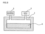
- the casting step (b-3) using a pressureless permeation method in which the molten metal is caused to permeate the composite material obtained in the step (a) is described below in detail with reference to FIGS. 2 and 3 .
- FIGS. 2 and 3 are schematic configuration diagrams of a device for producing the composite metal material by using the pressureless permeation method.
- a composite material 4 which is compression-formed in a forming die having a shape of the final product may be used, for example. It is preferable that the composite material 4 be not crosslinked. If the composite material 4 is not crosslinked, the permeation rate of the molten metal is increased.
- the composite material 4 such as a composite material 4 in which the filler particles 40 are mixed into the noncrosslinked elastomer 30 is placed in a sealed container 1. As shown in the enlarged diagram in FIG.
- the composite material 4 is formed in a state in which the filler particles 40 are dispersed in the matrix of the elastomer 30.
- a metal ingot such as an aluminum ingot 5 is disposed on the composite material 4.
- the composite material 4 and the aluminum ingot 5 disposed in the container 1 are heated to a temperature equal to or higher than the melting point of aluminum by using a heating means (not shown) provided at the container 1.
- the heated aluminum ingot 5 melts to become a molten aluminum metal (molten metal).
- the elastomer 30 in the composite material 4 which is in contact with the molten aluminum metal is decomposed and vaporized, and the molten aluminum metal (molten metal) permeates the space formed by decomposition of the elastomer 30.
- the space formed by decomposition of the elastomer 30 allows the molten aluminum metal to permeate the entire formed product due to a capillary phenomenon.
- the molten aluminum metal permeates the elastomer 30 by the capillary phenomenon, whereby the composite material is completely filled with the molten aluminum metal.
- the heating by the heating means of the container 1 is then terminated, and the molten metal which has permeated the composite material 4 is allowed to cool and solidify to obtain a composite metal material 6 as shown in FIG. 3 in which the filler particles 40 are uniformly dispersed.
- the atmosphere inside the container 1 may be removed by a decompression means 2 such as a vacuum pump connected with the container 1 before heating the container 1.
- Nitrogen gas may be introduced into the container 1 from an inert-gas supply means 3 such as a nitrogen gas cylinder connected with the container 1.
- the surface of the aluminum ingot 5 is covered with an oxide.
- the molecular end of the thermally decomposed elastomer becomes a radical, and the oxide (alumina) on the surface of the molten aluminum metal is reduced by the radical.
- the reducing atmosphere can be generated even inside the composite material by decomposition of the elastomer included in the composite material, the casting process using the pressureless permeation method can be performed without providing a reducing atmosphere processing chamber as in a conventional method.
- the reducing effect may be promoted by mixing magnesium particles in the composite material in advance as the reducing agent.
- the surfaces of the filler particles are activated by the radicals of the elastomer molecules decomposed by permeation of the molten aluminum metal, whereby wettability with the molten aluminum metal is improved.
- the composite metal material thus obtained includes the filler particles uniformly dispersed in the aluminum matrix.
- the pressureless permeation method is described as the step (b-3).
- a pressure permeation method which pressurizes the material by the pressure of inert gas atmosphere may also be used, for example.
- the permeation method in the step (b-3) since the elastomer in the composite material is replaced by the metal material, the dispersion state of the filler particles is uniform in comparison with another casting method. Therefore, the permeation method is relatively advantageous.
- the metal used in the casting step (b) may be appropriately selected from metals used in a conventional powder-forming and casting process, such as iron and an iron alloy, aluminum and an aluminum alloy, titanium and a titanium alloy, magnesium and a magnesium alloy, copper and a copper alloy, and zinc and a zinc alloy, either individually or in combination of two or more depending on the application.
- metals used in a conventional powder-forming and casting process such as iron and an iron alloy, aluminum and an aluminum alloy, titanium and a titanium alloy, magnesium and a magnesium alloy, copper and a copper alloy, and zinc and a zinc alloy, either individually or in combination of two or more depending on the application.
- Step 1 An open roll with a roll diameter of six inches (roll temperature: 10 to 20°C) was provided with a predetermined amount (100 g) (100 parts by weight (phr)) of an elastomer shown in Table 1, and the elastomer was wound around the roll.
- the elastomer natural rubber (NR) with a molecular weight of 3,000,000 was used.
- Step 2 Filler particles were added to the elastomer in an amount (parts by weight) shown in Table 1. The roll distance was set at 1.5 mm. As the filler particles, alumina (average particle diameter: 38 ⁇ m), SiC (average particle diameter: 45 ⁇ m), and tungsten (average particle diameter: 150 ⁇ m) were used.
- Step 3 After the addition of the filler particles, the mixture of the elastomer and the filler particles was removed from the rolls.
- Step 4 The roll distance was reduced from 1.5 mm to 0.3 mm, and the mixture was positioned in the open roll and tight milled.
- the surface velocity ratio of the two rolls was set at 1.1.
- the tight milling was repeated ten times.
- Step 5 The rolls were set at a predetermined distance (1.1 mm), and the mixture which had been tight milled was positioned and sheeted.
- Noncrosslinked composite materials of Examples 1 to 3 were obtained in this manner.
- the noncrosslinked composite material obtained in (1) was disposed in a container (furnace).
- An aluminum ingot (metal) was placed on the noncrosslinked composite material, and the composite material and the aluminum ingot were heated to the melting point of aluminum in an inert gas (nitrogen) atmosphere.
- the aluminum ingot melted to become a molten aluminum metal.
- the molten metal permeated the composite material to replace the elastomer in the composite material. After permeation of the molten aluminum metal was completed, the molten aluminum metal was allowed to cool and solidify to obtain composite metal materials of Examples 1 to 3.
- Comparative Example 1 a composite metal material sample obtained by adding filler particles to a molten aluminum metal in an amount shown in Table 1, stirring the mixture, and casting the stirred mixture was used.
- An aluminum alloy AC3C was used as the aluminum ingot in Examples 1 to 3 and Comparative Examples 1 and 2.
- the filler particles which can be generally dispersed in a matrix to only a small extent, can be uniformly dispersed in the metal matrix.
Landscapes
- Chemical & Material Sciences (AREA)
- Engineering & Computer Science (AREA)
- Mechanical Engineering (AREA)
- Materials Engineering (AREA)
- Metallurgy (AREA)
- Organic Chemistry (AREA)
- Manufacturing & Machinery (AREA)
- Composite Materials (AREA)
- Manufacture Of Alloys Or Alloy Compounds (AREA)
- Powder Metallurgy (AREA)
- Processes Of Treating Macromolecular Substances (AREA)
Claims (16)
- Un procédé de production d'un matériau métallique composite, le procédé comprenant :(a) le mélange d'un élastomère et de particules de charge de façon à obtenir un matériau composite, et(b) le mélange du matériau composite et d'un métal de façon à obtenir un matériau métallique composite dans lequel les particules de charge sont dispersées de manière uniforme dans le métal,où l'opération (b) ne comprend pas :le mélange d'un métal fondu dans un matériau composite contenant un élastomère qui comprend une liaison insaturée ou un groupe possédant une affinité pour des nanofibres de carbone, des particules métalliques mélangées à celui-ci et des nanofibres de carbone dispersées dans celui-ci par une force de cisaillement, oula perméation d'un métal fondu dans le produit formé d'un composite de fibres de carbone obtenu par la formation en une forme prédéterminée d'un matériau composite de fibres de carbone contenant un élastomère qui comprend une liaison insaturée ou un groupe possédant une affinité pour des nanofibres de carbone et des particules métalliques et des nanofibres de carbone dispersées dans l'élastomère, ladite perméation d'un métal fondu étant destinée à remplacer l'élastomère du produit formé d'un composite de fibres de carbone par le métal perméé dans le produit formé d'un composite de fibres de carbone, oula perméation d'un métal fondu dans le produit formé d'un composite de fibres de carbone obtenu par la réticulation d'un matériau composite de fibres de carbone contenant un élastomère qui comprend une liaison insaturée ou un groupe possédant une affinité pour des nanofibres de carbone et des particules métalliques et des nanofibres de carbone dispersées dans l'élastomère, ladite perméation d'un métal fondu étant destinée à remplacer l'élastomère du produit formé d'un composite de fibres de carbone par le métal perméé dans le produit formé d'un composite de fibres de carbone, oula perméation d'un métal fondu dans le produit formé d'un composite de fibres de carbone obtenu par la réticulation et la formation en une forme prédéterminée d'un matériau composite de fibres de carbone contenant un élastomère qui comprend une liaison insaturée ou un groupe possédant une affinité pour des nanofibres de carbone et des particules métalliques et des nanofibres de carbone dispersées dans l'élastomère, ladite perméation d'un métal fondu étant destinée à remplacer l'élastomère du produit formé d'un composite de fibres de carbone par le métal perméé dans le produit formé d'un composite de fibres de carbone.
- Le procédé de production d'un matériau métallique composite selon la revendication 1, où l'opération (b) comprend la décomposition et l'élimination de l'élastomère dans le matériau composite lors du mélange du matériau composite et du métal.
- Le procédé de production d'un matériau métallique composite selon la revendication 1 ou 2, où l'opération (a) comprend le mélange et la dispersion des particules de charge dans l'élastomère par une force de cisaillement.
- Le procédé de production d'un matériau métallique composite selon l'une quelconque des revendications 1 à 3,
où l'opération (b) comprend la formation en poudre du matériau composite. - Le procédé de production d'un matériau métallique composite selon l'une quelconque des revendications 1 à 3,
où l'opération (b) comprend le mélange du matériau composite et du métal en un état fluide et une opération consistant à amener le mélange à se solidifier. - Le procédé de production d'un matériau métallique composite selon l'une quelconque des revendications 1 à 3,
où l'opération (b) comprend une opération consistant à amener le métal fondu à perméer le matériau composite de façon à remplacer l'élastomère par le métal fondu. - Le procédé de production d'un matériau métallique composite selon l'une quelconque des revendications 1 à 6,
où les particules de charge sont des particules de charge métalliques. - Le procédé de production d'un matériau métallique composite selon l'une quelconque des revendications 1 à 6,
où les particules de charge sont des particules de charge non métalliques. - Le procédé de production d'un matériau métallique composite selon la revendication 8, où les particules de charge non métalliques sont des particules de charge céramiques.
- Le procédé de production d'un matériau métallique composite selon l'une quelconque des revendications 1 à 9,
où l'élastomère possède une masse moléculaire de 5 000 à 5 000 000. - Le procédé de production d'un matériau métallique composite selon l'une quelconque des revendications 1 à 10,
où au moins une chaîne parmi une chaîne principale, une chaîne latérale et une chaîne terminale de l'élastomère contient au moins un élément parmi une liaison double, une liaison triple, α-hydrogène, un groupe carbonyle, un groupe carboxyle, un groupe hydroxyle, un groupe amino, un groupe nitrile, un groupe cétone, un groupe amide, un groupe époxy, un groupe ester, un groupe vinyle, un groupe halogène, un groupe uréthane, un groupe biuret, un groupe allophanate et un groupe urée. - Le procédé de production d'un matériau métallique composite selon l'une quelconque des revendications 1 à 11,
où un composant de réseau de l'élastomère dans une forme non réticulée possède un temps de relaxation spin-spin (T2n) mesuré à 30°C par un procédé d'écho de Hahn au moyen d'une technique de résonance magnétique nucléaire pulsée (NMR) de 100 à 3 000 µsec. - Le procédé de production d'un matériau métallique composite selon l'une quelconque des revendications 1 à 12,
où un composant de réseau de l'élastomère dans une forme réticulée possède un temps de relaxation spin-spin (T2n) mesuré à 30°C par un procédé d'écho de Hahn au moyen d'une technique de résonance magnétique nucléaire pulsée (NMR) de 100 à 2 000 µsec. - Le procédé de production d'un matériau métallique composite selon l'une quelconque des revendications 1 à 13,
où le métal est aluminium ou un alliage d'aluminium. - Le procédé selon l'une quelconque des revendications 1 à 14 comprenant en outre l'utilisation du matériau métallique composite sous la forme d'un lingot et la formation de celui en une forme souhaitée.
- Le procédé selon la revendication 15, où la formation en une forme souhaitée est exécutée au moyen d'un procédé de coulée, un procédé de forgeage de poudre, un procédé d'extrusion de poudre ou un procédé de formation par injection de poudre.
Applications Claiming Priority (2)
| Application Number | Priority Date | Filing Date | Title |
|---|---|---|---|
| JP2004021146A JP4224407B2 (ja) | 2004-01-29 | 2004-01-29 | 複合金属材料の製造方法 |
| JP2004021146 | 2004-01-29 |
Publications (3)
| Publication Number | Publication Date |
|---|---|
| EP1559800A2 EP1559800A2 (fr) | 2005-08-03 |
| EP1559800A3 EP1559800A3 (fr) | 2006-12-20 |
| EP1559800B1 true EP1559800B1 (fr) | 2014-12-17 |
Family
ID=34650812
Family Applications (1)
| Application Number | Title | Priority Date | Filing Date |
|---|---|---|---|
| EP05250437.0A Expired - Lifetime EP1559800B1 (fr) | 2004-01-29 | 2005-01-27 | Matériau métallique composite et son procédé de préparation |
Country Status (5)
| Country | Link |
|---|---|
| US (1) | US7252135B2 (fr) |
| EP (1) | EP1559800B1 (fr) |
| JP (1) | JP4224407B2 (fr) |
| KR (1) | KR100643725B1 (fr) |
| CN (1) | CN100564020C (fr) |
Families Citing this family (13)
| Publication number | Priority date | Publication date | Assignee | Title |
|---|---|---|---|---|
| JP4005058B2 (ja) * | 2003-07-23 | 2007-11-07 | 日信工業株式会社 | 炭素繊維複合材料及びその製造方法、炭素繊維複合成形品及びその製造方法 |
| JP4224428B2 (ja) * | 2004-05-24 | 2009-02-12 | 日信工業株式会社 | 金属材料の製造方法、炭素繊維複合金属材料の製造方法 |
| JP4224438B2 (ja) * | 2004-07-16 | 2009-02-12 | 日信工業株式会社 | 炭素繊維複合金属材料の製造方法 |
| US8052918B2 (en) * | 2004-07-21 | 2011-11-08 | Nissin Kogyo Co., Ltd. | Carbon-based material and method of producing the same, and composite material and method of producing the same |
| JP4293957B2 (ja) | 2004-09-03 | 2009-07-08 | 日信工業株式会社 | 炭素系材料及びその製造方法、複合材料の製造方法 |
| JP4279220B2 (ja) * | 2004-09-09 | 2009-06-17 | 日信工業株式会社 | 複合材料及びその製造方法、複合金属材料及びその製造方法 |
| JP2007039638A (ja) * | 2005-03-23 | 2007-02-15 | Nissin Kogyo Co Ltd | 炭素繊維複合材料 |
| JP4224499B2 (ja) | 2005-06-30 | 2009-02-12 | 日信工業株式会社 | 繊維複合材料の製造方法 |
| JP2007039649A (ja) * | 2005-06-30 | 2007-02-15 | Nissin Kogyo Co Ltd | 複合材料 |
| JP5188425B2 (ja) * | 2009-03-09 | 2013-04-24 | 日本碍子株式会社 | 坏土の評価方法、及び坏土の製造方法 |
| CN103233189A (zh) * | 2013-04-18 | 2013-08-07 | 邱献腾 | 一种铝基复合材料及其加工工艺 |
| CN107267840B (zh) * | 2017-06-06 | 2019-01-29 | 苏州轩朗塑料制品有限公司 | 多孔泡沫生物质复合金属材料的制备方法 |
| JP7683278B2 (ja) | 2021-03-30 | 2025-05-27 | セイコーエプソン株式会社 | チクソ成形用材料、チクソ成形用材料の製造方法およびチクソ成形体 |
Family Cites Families (14)
| Publication number | Priority date | Publication date | Assignee | Title |
|---|---|---|---|---|
| JPS59177336A (ja) | 1983-03-25 | 1984-10-08 | Nippon Denso Co Ltd | 繊維強化金属複合材料の製造方法 |
| DE3686239T2 (de) * | 1985-11-14 | 1993-03-18 | Ici Plc | Faserverstaerkter verbundwerkstoff mit metallmatrix. |
| US5108964A (en) * | 1989-02-15 | 1992-04-28 | Technical Ceramics Laboratories, Inc. | Shaped bodies containing short inorganic fibers or whiskers and methods of forming such bodies |
| AU5336190A (en) | 1989-03-03 | 1990-09-26 | Hyperion Catalysis International | Applications for graphite fibrils |
| IT1230775B (it) * | 1989-05-05 | 1991-10-29 | Sir Ind Spa | Preforme ceramiche per compositi a matrice metallica, procedimento per la loro preparazione e compositi con esse ottenuti. |
| KR100256365B1 (ko) | 1995-11-30 | 2000-05-15 | 이구택 | 방향성을 갖는 금속복합재료의 제조방법 |
| JP2002020801A (ja) | 2000-07-07 | 2002-01-23 | Kawasaki Steel Corp | 粉末冶金用鉄基混合粉 |
| JP2002115017A (ja) | 2000-10-10 | 2002-04-19 | Aisin Takaoka Ltd | アルミニウム基複合材料の製造方法 |
| IL142254A0 (en) | 2001-03-26 | 2002-03-10 | Univ Ben Gurion | Method for the preparation of stable suspensions of single carbon nanotubes |
| KR100592527B1 (ko) | 2002-01-17 | 2006-06-23 | (주)케이에이치 케미컬 | 탄소나노튜브를 강화제로 포함하는 고무 조성물 및 이의제조방법 |
| JP4005048B2 (ja) * | 2003-04-09 | 2007-11-07 | 日信工業株式会社 | 炭素繊維複合材料およびその製造方法 |
| JP4005058B2 (ja) * | 2003-07-23 | 2007-11-07 | 日信工業株式会社 | 炭素繊維複合材料及びその製造方法、炭素繊維複合成形品及びその製造方法 |
| JP4177210B2 (ja) | 2003-09-04 | 2008-11-05 | 日信工業株式会社 | 炭素繊維複合金属材料の製造方法 |
| JP4224445B2 (ja) * | 2004-02-06 | 2009-02-12 | 日信工業株式会社 | カーボンブラック複合材料の製造方法 |
-
2004
- 2004-01-29 JP JP2004021146A patent/JP4224407B2/ja not_active Expired - Fee Related
-
2005
- 2005-01-25 US US11/041,258 patent/US7252135B2/en not_active Expired - Lifetime
- 2005-01-27 EP EP05250437.0A patent/EP1559800B1/fr not_active Expired - Lifetime
- 2005-01-27 KR KR1020050007697A patent/KR100643725B1/ko not_active Expired - Fee Related
- 2005-01-28 CN CNB2005100509135A patent/CN100564020C/zh not_active Expired - Fee Related
Also Published As
| Publication number | Publication date |
|---|---|
| US20050194115A1 (en) | 2005-09-08 |
| KR100643725B1 (ko) | 2006-11-10 |
| KR20050077770A (ko) | 2005-08-03 |
| CN1647916A (zh) | 2005-08-03 |
| CN100564020C (zh) | 2009-12-02 |
| JP4224407B2 (ja) | 2009-02-12 |
| US7252135B2 (en) | 2007-08-07 |
| JP2005213577A (ja) | 2005-08-11 |
| EP1559800A2 (fr) | 2005-08-03 |
| EP1559800A3 (fr) | 2006-12-20 |
Similar Documents
| Publication | Publication Date | Title |
|---|---|---|
| EP1500677B1 (fr) | Matériau composite de fibres de carbone-mé tal et son procédé de fabrication | |
| EP1616972B1 (fr) | Matériau composite à matrice métallique renforcé à la fibre de carbone et son procédé de fabrication | |
| EP1600231B1 (fr) | Materiau métallique et méthode de fabrication, matériau composite de métal et fibres de carbone et son procédé de fabrication | |
| EP2287237A1 (fr) | Matériau composite de fibres de carbone et son procédé de fabrication, matériau composite de fibres de carbone à base de métal et son procédé de fabrication, matériau composite de fibres de carbone à base de non-métal et son procédé de fabrication | |
| US7252135B2 (en) | Composite metal material and method of producing the same | |
| EP1561771B1 (fr) | Composite formé de noir de carbone et son procédé de préparation, et composition d'élastomère | |
| EP1637255B1 (fr) | Matériau composite métallique et sa méthode de production | |
| EP1619262B1 (fr) | Materiau à base de carbone, son procédé de production, matériau composite et son procédé de production | |
| JP4005018B2 (ja) | 炭素繊維複合材料及びその製造方法、炭素繊維複合成形品及びその製造方法 | |
| JP4224418B2 (ja) | 繊維複合金属材料の製造方法 | |
| JP4224388B2 (ja) | ウイスカ複合金属材料の製造方法 |
Legal Events
| Date | Code | Title | Description |
|---|---|---|---|
| PUAI | Public reference made under article 153(3) epc to a published international application that has entered the european phase |
Free format text: ORIGINAL CODE: 0009012 |
|
| AK | Designated contracting states |
Kind code of ref document: A2 Designated state(s): AT BE BG CH CY CZ DE DK EE ES FI FR GB GR HU IE IS IT LI LT LU MC NL PL PT RO SE SI SK TR |
|
| AX | Request for extension of the european patent |
Extension state: AL BA HR LV MK YU |
|
| PUAL | Search report despatched |
Free format text: ORIGINAL CODE: 0009013 |
|
| AK | Designated contracting states |
Kind code of ref document: A3 Designated state(s): AT BE BG CH CY CZ DE DK EE ES FI FR GB GR HU IE IS IT LI LT LU MC NL PL PT RO SE SI SK TR |
|
| AX | Request for extension of the european patent |
Extension state: AL BA HR LV MK YU |
|
| RIC1 | Information provided on ipc code assigned before grant |
Ipc: C22C 1/10 20060101AFI20050511BHEP Ipc: B22F 1/00 20060101ALI20061116BHEP |
|
| 17P | Request for examination filed |
Effective date: 20070613 |
|
| AKX | Designation fees paid |
Designated state(s): DE FR GB |
|
| 17Q | First examination report despatched |
Effective date: 20120319 |
|
| RIC1 | Information provided on ipc code assigned before grant |
Ipc: B22D 19/14 20060101ALI20140624BHEP Ipc: B22F 1/00 20060101ALI20140624BHEP Ipc: C22C 1/10 20060101AFI20140624BHEP Ipc: B22F 3/26 20060101ALI20140624BHEP |
|
| GRAP | Despatch of communication of intention to grant a patent |
Free format text: ORIGINAL CODE: EPIDOSNIGR1 |
|
| INTG | Intention to grant announced |
Effective date: 20140813 |
|
| GRAS | Grant fee paid |
Free format text: ORIGINAL CODE: EPIDOSNIGR3 |
|
| GRAA | (expected) grant |
Free format text: ORIGINAL CODE: 0009210 |
|
| RAP1 | Party data changed (applicant data changed or rights of an application transferred) |
Owner name: NISSIN KOGYO CO., LTD. |
|
| RIN1 | Information on inventor provided before grant (corrected) |
Inventor name: MAGARIO, AKIRA Inventor name: NOGUCHI, TORU |
|
| AK | Designated contracting states |
Kind code of ref document: B1 Designated state(s): DE FR GB |
|
| REG | Reference to a national code |
Ref country code: GB Ref legal event code: FG4D |
|
| REG | Reference to a national code |
Ref country code: DE Ref legal event code: R096 Ref document number: 602005045443 Country of ref document: DE Effective date: 20150205 |
|
| REG | Reference to a national code |
Ref country code: DE Ref legal event code: R097 Ref document number: 602005045443 Country of ref document: DE |
|
| PLBE | No opposition filed within time limit |
Free format text: ORIGINAL CODE: 0009261 |
|
| STAA | Information on the status of an ep patent application or granted ep patent |
Free format text: STATUS: NO OPPOSITION FILED WITHIN TIME LIMIT |
|
| 26N | No opposition filed |
Effective date: 20150918 |
|
| REG | Reference to a national code |
Ref country code: FR Ref legal event code: PLFP Year of fee payment: 12 |
|
| REG | Reference to a national code |
Ref country code: FR Ref legal event code: PLFP Year of fee payment: 13 |
|
| REG | Reference to a national code |
Ref country code: FR Ref legal event code: PLFP Year of fee payment: 14 |
|
| REG | Reference to a national code |
Ref country code: DE Ref legal event code: R082 Ref document number: 602005045443 Country of ref document: DE Representative=s name: HL KEMPNER PATENTANWALT, RECHTSANWALT, SOLICIT, DE |
|
| PGFP | Annual fee paid to national office [announced via postgrant information from national office to epo] |
Ref country code: FR Payment date: 20201210 Year of fee payment: 17 |
|
| PGFP | Annual fee paid to national office [announced via postgrant information from national office to epo] |
Ref country code: DE Payment date: 20210112 Year of fee payment: 17 Ref country code: GB Payment date: 20210120 Year of fee payment: 17 |
|
| REG | Reference to a national code |
Ref country code: DE Ref legal event code: R119 Ref document number: 602005045443 Country of ref document: DE |
|
| GBPC | Gb: european patent ceased through non-payment of renewal fee |
Effective date: 20220127 |
|
| PG25 | Lapsed in a contracting state [announced via postgrant information from national office to epo] |
Ref country code: GB Free format text: LAPSE BECAUSE OF NON-PAYMENT OF DUE FEES Effective date: 20220127 Ref country code: DE Free format text: LAPSE BECAUSE OF NON-PAYMENT OF DUE FEES Effective date: 20220802 |
|
| PG25 | Lapsed in a contracting state [announced via postgrant information from national office to epo] |
Ref country code: FR Free format text: LAPSE BECAUSE OF NON-PAYMENT OF DUE FEES Effective date: 20220131 |