EP1559854A2 - Structure repliable en toile - Google Patents
Structure repliable en toile Download PDFInfo
- Publication number
- EP1559854A2 EP1559854A2 EP05250512A EP05250512A EP1559854A2 EP 1559854 A2 EP1559854 A2 EP 1559854A2 EP 05250512 A EP05250512 A EP 05250512A EP 05250512 A EP05250512 A EP 05250512A EP 1559854 A2 EP1559854 A2 EP 1559854A2
- Authority
- EP
- European Patent Office
- Prior art keywords
- base
- fabric
- canopy
- tent
- frame members
- Prior art date
- Legal status (The legal status is an assumption and is not a legal conclusion. Google has not performed a legal analysis and makes no representation as to the accuracy of the status listed.)
- Withdrawn
Links
Images




Classifications
-
- E—FIXED CONSTRUCTIONS
- E04—BUILDING
- E04H—BUILDINGS OR LIKE STRUCTURES FOR PARTICULAR PURPOSES; SWIMMING OR SPLASH BATHS OR POOLS; MASTS; FENCING; TENTS OR CANOPIES, IN GENERAL
- E04H15/00—Tents or canopies, in general
- E04H15/006—Tents used as toys
-
- E—FIXED CONSTRUCTIONS
- E04—BUILDING
- E04H—BUILDINGS OR LIKE STRUCTURES FOR PARTICULAR PURPOSES; SWIMMING OR SPLASH BATHS OR POOLS; MASTS; FENCING; TENTS OR CANOPIES, IN GENERAL
- E04H15/00—Tents or canopies, in general
- E04H15/32—Parts, components, construction details, accessories, interior equipment, specially adapted for tents, e.g. guy-line equipment, skirts, thresholds
- E04H15/34—Supporting means, e.g. frames
- E04H15/36—Supporting means, e.g. frames arch-shaped type
- E04H15/38—Supporting means, e.g. frames arch-shaped type expansible, e.g. extensible in a fan type manner
-
- E—FIXED CONSTRUCTIONS
- E04—BUILDING
- E04H—BUILDINGS OR LIKE STRUCTURES FOR PARTICULAR PURPOSES; SWIMMING OR SPLASH BATHS OR POOLS; MASTS; FENCING; TENTS OR CANOPIES, IN GENERAL
- E04H15/00—Tents or canopies, in general
- E04H15/32—Parts, components, construction details, accessories, interior equipment, specially adapted for tents, e.g. guy-line equipment, skirts, thresholds
- E04H15/34—Supporting means, e.g. frames
- E04H15/36—Supporting means, e.g. frames arch-shaped type
- E04H15/40—Supporting means, e.g. frames arch-shaped type flexible
Definitions
- the present specification relates to collapsible, fabric structures, for example, tents, children's play structures, tunnels and shade structures having an igloo/dome tent shape.
- a foldable tent structure having an igloo/dome tent shape is known from US Patent 2,167,219. It discloses a foldable tent with a generally circular base made from four rod segments. Two further arcuate rods are provided hinged to the base rods to support a fabric canopy. The structure is erected by folding out the structure like a fan and linking the rods of the base together to form a continuous loop.
- a problem with the structure is that it is bulky to carry as the arcuate rods that support the canopy are long, rigid, semi-circular rods. If the rods were removed from the fabric canopy then they would be difficult to feed back into their locating fabric pockets.
- the present invention presents a solution to this problem by providing a structure of similar external shape that can be readily assembled from a more compact storage configuration, for example, a storage configuration suitable for shipping and marketing of the product.
- Igloo/dome tents which use collapsible rods, for example, made of fibre reinforced resins, have become popular for camping and these can take many forms.
- a campsite it is necessary to assemble the collapsible rods into long flexible frame members which are then fed into sleeves or pockets that connect the fabric of the tent to the frame members.
- the fabric induces a curve in the frame members and it can be difficult to feed these members into the sleeves or pockets because of friction and snagging.
- the base of the structure can also lack form at this stage and this can also make it difficult to insert the frame members. In some instances, users may peg out the base of their tent to assist with the insertion of the frame members.
- igloo/dome tents have become available recently that are based on frame members in the form of coilable loops. In many instances these can self- erect upon release from their storage configuration with little or no intervention by the camper. US-A-4,858,634, US-A-5,163,461, US-A-5,337,772 and US-A-6,363,955 are examples of these. These tent structures, however, are complicated and expensive to manufacture. In addition, many users are not able to follow the instructions to collapse these structures back into their most compact configuration in which they are coiled up into a loop a third of the size of the expanded loop structure. Users may also lose the instructions after purchase and not be able to figure out how to fully collapse the structures.
- This non-coiling is particularly a problem with play structures intended for indoor use that are of a much smaller scale than the adult equivalents, as their partially folded condition where the frame members are simply folded together and not coiled may be seen as "small enough", for example, to store behind a sofa or in a cupboard.
- a collapsible fabric structure in the form of an igloo/ dome tent having a base frame member and at least two additional canopy supporting frame members extending as arches from common points on the base frame member to support the fabric canopy of the tent, wherein the canopy supporting frame members each comprise a plurality of rods that are connected together and fed into means (for example sleeves, loops or pockets) which locate the fabric to the frame members and force the frame members into an arcuate form, and wherein the base frame member comprises a resilient member in the form of a loop which extends around substantially the perimeter of the structure to expand the base upon release from a collapsed configuration.
- loop base frame member provides form to the structure prior to the insertion of the canopy supporting frame members. This makes it easier for the user to locate the frame members in the sleeves, loops or pockets and slide them into the fabric structure.
- the user will also be familiar with the way the rods of the canopy supporting frame members connect together and feed into the sleeves, loops or pockets of the fabric structure from existing igloo/dome tent structures. After use, these frame members can be extracted leaving the fabric structure with just a resilient loop frame member in its base.
- the presence of just a single coilable member, rather than two or more coilable frame members, means that the tent can be coiled up into a more compact configuration with greater ease and this may be within the capability of the user even after the instructions have been lost.
- the structure may instead be simply folded in half for storage purposes.
- the loop base frame member is sufficiently resilient to allow the loop to be folded in two.
- the arch-like canopy supporting frame members hinge about the fold line, where the ends of these frame members meet the base frame member at the common points, so as to fold flat against each other like the pages of a book.
- a fastener for example, in the form of Velcro, a tie, a buckle, a push fastener, button, etc., may be provided to secure the structure in this partially collapsed configuration.
- the resilience of the base loop frame member means that the structure is self-opening from this partially collapsed configuration and provides some tension into the fabric canopy. Preferably this is sufficient to allow the structure to be used indoors, i.e., without the aid of tent pegs.
- ties or pockets for sand may also be provided to secure the structure to the ground in the case of outdoor use. These may also serve to pull the structure slightly tauter.
- the structure has a coilable member in the form of a fibre reinforced resin wire, more preferably an epoxy based wire, and in particular one in which at least the surface layer of fibre is wound helically around the core of the wire.
- the wire is preferably between 1 and 4 mm in diameter, more preferably 2-3 mm, and readily deformable to allow it to be coiled easily.
- a resilient strip e.g., of steel can be used to form the loop, although this is seen as less desirable for play structures than the fibre reinforced resin wire because it may present a sharp edge in the base which could hurt a young child and can be more difficult to coil up.
- the base may be generally circular or a more complex ornamental shape, for example, including features to replicate the appearance of a flower, animal, insect, bird etc. However more preferably the base has a substantially oval perimeter with major and minor axes. In such arrangements the structure will fold about the minor axis to bring the ends of the structure (the ends of the major axis) together.
- the base frame member may extend around the perimeter of the design, or more preferably in an oval shape within but still relatively close to the edge of the structure. For example, petals of a flower design could be created by providing additional curved areas of fabric extending out from the base frame member.
- the base of the structure can be coiled into three loops once the canopy supporting members have been removed. This will reduce the base to approximately one third of its size.
- Fastening means for example, snap fasteners, straps, ties, Velcro, zips etc may be provided to retain the structure in a fully collapsed configuration. This can help hold the structure in a compact form for ease of putting it away into a storage bag.
- the ends of three arch-like canopy supporting frame members meet substantially where the base frame member crosses the minor axis of the elliptical base (the "common points").
- the frame members do not need to contact each other, though they do need to be sufficiently close to transfer forces to hold the canopy in an expanded configuration.
- there would be a central arch disposed substantially perpendicular to the base and second and third arches disposed to each side dividing the right angle between the central arch and the base.
- Arrangements are also envisaged where four or more arch-like canopy supporting members are provided.
- the structure may also include additional arch or other frame members that are hinged to the base at positions between a central fold line (the minor axis) and an end of the base (an end of a major axis), for example, as supports for doorways.
- Arch frame members on one side of a centre line e.g., the minor axis of an oval base, should all hinge and fold flat in the same direction, and all arch members on the other side should all hinge and fold flat in the opposite direction during folding together of the opposing end portions.
- the arch frame members may be made of a similar material to the loop frame member.
- conventional fibre reinforced resin rods for example, of between 2 to 4 mm in diameter and between 30 to 60 mm in length, are adequate for the purpose and provide a cost effect solution to supporting the fabric canopy.
- Connectable rods of this type for example, fitted with sleeves to provide male/female connections are known from existing tent structures and so will be familiar to the user in terms of assembly and disassembly of the frame members.
- the ends of the frame members may be fitted with pads to reduce snagging and their respective receiving pockets may be reinforced to prevent wear.
- the base of the structure includes a floor panel so that the interior space is enclosed from above and below.
- a floor panel so that the interior space is enclosed from above and below.
- an entrance is provided to give access to the interior. Entrances are preferably closable with a door that can be fastened in its closed position. Preferably such an entrance and door has an arcuate edge with the base of the door remaining connected to the base of the structure. This creates a partial disc shaped mat when the door is opened and resting on the ground. In addition to the aesthetics, such an arrangement avoids the creation of a potential trip hazard for a young child. This may be important in a structure having entrances in opposite ends and functioning as a tunnel for the child to run or crawl down.
- the floor panel may include additional detail to continue features provided on the door, for example, to give the appearance of a full disc at the entrance to the structure.
- a zip may be provided as a means for closing the door or other fastening means such as Velcro, snap fasteners, ties, etc., may be used instead.
- a second entrance and door may be provided of the same or a different shape.
- An additional resilient member e.g., in the form of an arch, may be incorporated into the door entrance to support the fabric when the door is open.
- fabric is intended to cover any sheet-like flexible material that might be used for such a structure, for example, a woven fabric, film, netting, transparent or coloured sheet material.
- the structure may include windows of transparent or coloured material and may include openings and other features as amusement features.
- the new structure has great applicability for use as play structures, for example, in the form of play tents or tunnels.
- the structure can also be used in full size structures for grown-ups.
- the first aspect of the present invention uses the resilience of a flexible coilable frame member in the base of the structure to open up the structure into an erected configuration.
- the present specification also concerns other structures having substantially the same shape, which through a function of the base, also expand into an erected structure.
- the base of the structure is elliptical and the two additional frame members hinge about axes which are parallel to the minor axis but spaced approximately midway between the minor axis and the ends of the structure that extend in the direction of the major axis. Straps or webs of fabric connecting these additional loops to the ends of the base pull the loops into their substantially upright configuration to hold the fabric in a tunnel shape.
- the present invention provides a collapsible fabric structure in the form of an igloo/dome tent having at least two canopy supporting frame members extending as arches from common points on a base of the structure to support the fabric canopy of the tent, wherein the base comprises an air chamber.
- the base can be inflated to expand the structure from a storage configuration to an erected configuration.
- the inflated base acts as a tensioning element to pull the fabric canopy taut. It is also comfortable on the knees of young children as they are crawling through the structure and provides an amusement feature.
- the air chamber provides the base with necessary form and rigidity to make insertion of the rods simpler, as with the first aspect of the present invention.
- the air chamber is inflated to give the base rigidity. It is this rigidity and form that pulls the rest of the structure into an erected configuration in a similar way to inflatable bouncy castles.
- the air chamber also acts as a mattress to provide a play structure in the form of a tent that children can sleep in or play in comfortably.
- the structures of the second aspect are substantially the same as the first aspect and the comments made above in relation to the first aspect apply equally to the second.
- the base will need to be of about 4 to 15 cm thick, preferably about 10 cm thick to accommodate the air chamber.
- the air chamber is made of plastic and retained within a fabric pocket of the base of the structure.
- the air chamber is an integral part of the structure.
- the air chamber is a fabric coated material that is fixed to the rest of the structure.
- the air chamber may also be removable from the rest of the structure and connected to the structure by a releasable connection, for example Velcro®, press fasteners, buttons, ties, straps and buckles, etc.
- the tent of the first aspect is provided with releasable connections to attach an inflatable chamber to the base of the structure.
- a collapsible fabric structure in the form of an igloo/dome tent comprising a fabric canopy, at least two canopy supporting frame members extending as arches from common points on a base of the structure to support the fabric canopy of the tent and a base comprising an inflatable air chamber, wherein the canopy supporting frame members and the canopy are secured to the base by releasable connections so that the base can be separated from the frame members and canopy for storage purposes.
- the structure has the canopy supporting frame members which pivot about the common points in relation to the base, wherein one side of the fabric canopy (i.e., a portion extending from one common point around one end of the base to the other common point) is provided with releasable connections for detaching the fabric canopy from the base.
- one side detached from the base the fabric canopy can be folded down onto the base by rotating the arches about their common points, in a similar way to folding down a hood of a car.
- an advantage of this embodiment is that the inflatable air chamber provides rigidity and form to the structure. Once inflated, attachment of the additional tent components is a relatively simple task and it would be easy for the average person to work out how to erect and disassemble the structure even if the instructions had become lost.
- the arches are semi-circular and the base is circular.
- the fabric canopy in two halves that are connected at a suitable halfway point, for example a central arch member.
- the two halves can be connected to the inflated base if they are not already fitted, and the canopy erected through manually pulling together the two halves of the canopy together until the canopy is pulled substantially taut against the rigidity of the base.
- a further development disclosed herein provides a self-erecting, collapsible, fabric structure comprising a base and a canopy of fabric to define an interior within, the base having a resilient frame member in the form of a loop extending around a periphery thereof, the base being substantially elliptical and foldable about its minor axis such that the end portions of the structure can be folded together to collapse the structure, wherein the canopy is supported by at least two additional frame members which are in the form of arches that extend from the base, the ends of each arch frame member being positioned substantially on the minor axis such that the arches are capable of hinging with respect to the base so that they fold flat when the end portions of the base are folded together.
- the structure is self-erecting in the sense that it will pop open into an expanded configuration upon release from a collapsed configuration.
- the base loop frame member is resilient and therefore resists any deflection out of a plane or neutral position. This resilience provides a force on the rest of the structure which is sufficient to expand it from a collapsed configuration into an expanded configuration and to pull the fabric of the canopy sufficiently taut for use as a play structure.
- This development may incorporate any of the features described in connection with the other tents.
- FIG. 1 there is shown a perspective view of a preferred tent 1 structure according to the first aspect of the present invention.
- the fabric canopy for the tent 1 has been omitted for clarity.
- the structure in its most basic form consists of a base frame member 2 and at least two canopy supporting frame members 3 (in the embodiment illustrated there are three) extending from common points 4 of the base frame member 2.
- the base frame member 2 may consist of resilient metal strip formed into a loop.
- the nature of the strip profile means that the loop has a neutral position when it is flat. Bending the loop out of this plane is resisted by the resilience of the strip, which is forced to bend and deflect to allow deflection out of the plane. In the present invention, this resilience provides the force to keep the structure in its erected or substantially erected configuration.
- a fibre reinforced member (wire or rod) is used in place of the steel strip.
- Such members tend to have a circular profile, which while this has an effect on the deflection characteristics because of the isotropic properties of the material, it is preferred from the point of view of not presenting a sharp edge at a location where a small child could be crawling over.
- the most preferred material of this type is manufactured by a company called Sportex and takes the form of an epoxy wire reinforced with longitudinal glass fibre or other material and bound at its surface with a helically wound thread. It has good all-round bend characteristics without suffering from delamination after repeated deflection.
- the base frame member 2 is preferably housed within a sleeve that extends around the periphery of a floor panel that forms the base of the tent 1.
- the periphery constrains the base frame member 2 into a circular form, or more preferably an oval shape as shown with major axis A-A and minor axis B-B.
- the floor panel (not shown) is preferably cut so that it is pulled taut by the base frame member 2.
- a central arch 3 is positioned in a substantially upright configuration and two further arches 3 are positioned either side inclined at an angle ⁇ to the first one.
- the angle ⁇ is preferably between 30 to 60 degrees and more preferably about 45 degrees.
- All three canopy supporting frame members 3 are preferably of the same size and arranged to pivot about their free ends 5 at the common points 4. In this way the two inclined arches 3 can be pivoted between a storage configuration where they are stacked flat side by side against the central arch, and an erected configuration as shown in Figure 1 where they are inclined to the central arch by an angle ⁇ .
- the canopy supporting frame members 3 can be made of any suitable frame material. It is preferred to use conventional glass fibre rod material which has been cut into transportable lengths and which can be joined together to form the arches during the erection of the tent from a cost point of view. Conventional metal sleeves can be used as suitable connectors for this. A set of rods may also be joined together by a length of elastic material running through the middle of the rods. Alternatively more exotic material such as the helically bound rods described above can be used. In such an embodiment, due to the bendability of the material, the frame members 3 may consist of single lengths of wire that remain housed within sleeves of the structure during erection and collapsing of the tent into a compact size for shipping.
- the frame members 2,3 are housed within sleeves sewn into the fabric canopy.
- loops, pockets or any other suitable feature may be used to secure the fabric to the frame members 2,3.
- the sleeves may include reinforced pockets at their ends to protect against wear from the free ends 5 of the arches 3.
- the free ends 5 of the arches 3 are shown close together at the common points 4 so that the points of pivot allow the arches 3 to be folded flat against each other and to provide a neat arrangement.
- common point 4 is used in a broad sense, in that it is possible for the free ends 5 to be slightly more spaced apart and for the arches to fold approximately flat, but a better effect is achieved when the free ends are positioned closer together and so this is preferred.
- the two ends of the base are folded together like closing a book. If it is desired to collapse the structure further then the arches 3 can be dismantled and the base frame member 2 coiled into three loops. In the embodiments where coilable material is used for the arches, then it may be possible to leave these arches in place when coiling up the structure.
- two additional canopy supporting frame members 6 are provided spaced from the free ends 5 of the other three arches 3.
- These secondary arches 6 provide support to design features, for example a doorway. These may be made of finer gauge material than the primary arches 3.
- the arches are preferably of a size and in a position where when they fold flat against the central arch they adopt substantially the same profile to provide a neat arrangement for storage.
- Figure 2 is a side elevation viewing the structure in cross section along the major axis A-A.
- the fabric canopy 7 is supported by the arches to create a dome or igloo shape tent (a tent of substantially hemispherical shape).
- the fabric canopy 7 is pulled taut over the arches 3 by the resilience of the base frame member 2, the resilience urging the ends of the tent 1 (the portion of the perimeter lying on the major axis A-A) back into the neutral planar position.
- the resilience should be sufficient to provide a useable structure for indoor use.
- the tent 1 may also be provided with loops for tent pegs to allow outdoor use too, and these may pull the fabric canopy tauter.
- Pockets may also be provided for filling with sand for use on a beach as an alternative to tent pegs.
- the fabric canopy 7 may incorporate different materials, for example, netting or transparent material to provide windows, and may incorporate openings for children to view out of or climb out of.
- FIG. 3 illustrates the tent when viewed from one end looking down the major axis A-A.
- a doorway 8 can be seen, with the fabric immediately adjacent the doorway 8 supported by one of the secondary arches 6.
- a semi-circular doorway 8 is provided with a zip fastener 9 extending around the perimeter to close the door.
- the door 8 when fully unzipped, can fold down flat like a draw bridge, hinging about an axis perpendicular to the major axis along the junction with the base.
- a design is provided in this doorway to mimic the semi-circular door shape and create a disc.
- this disc incorporates a swirl pattern which is only visualised properly when the door 8 is open.
- Figure 4 shows an alternative tent 11 having a base 12 and three canopy supporting frame members (or arches) 13.
- the base 12 comprises an inflatable air chamber 20 which is shown more clearly in Figure 5.
- the three arches 13 meet at a common point 14 on the base 12. This allows the arches 13 to pivot with respect to the base 12 so that they can fold together to collapse the structure.
- the tent 11 may incorporate a range of different materials to increase interest for a child.
- the fabric canopy 17 is integral with the base 12 and the arches 13 are formed from helically bound fibre reinforced epoxy rods.
- the arches 13 are sufficiently flexible to allow the structure to be folded up without first having to remove these rods. Erection of the structure consists of simply inflating the base 12 with a pump, the air pressure within the base 12 being enough to unfold and expand the structure, and then pull the fabric canopy 17 taut. It is possible to use conventional rods if preferred, however these have the disadvantage that they cannot be coiled up into a smaller size for storage and therefore would need to be removed to reduce the collapsed tent to a smaller size.
- FIG. 5 An alternative method of erection is illustrated using Figures 5 through to 8.
- an inflatable chamber 20 of approximately circular form is shown in the top of the figure.
- the base 22 of the tent 21 is shown in the bottom of the figure in an inverted configuration.
- the air chamber is inflated to create an air mattress.
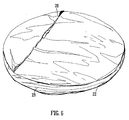
- This is then placed within the fabric envelope of the base 22 through the slot 28 to create the inflated base as shown in Figure 6.
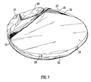
- the base 22 is then flipped over so that it is the correct way up as shown in Figure 7.
- Around a portion of the perimeter of the base 22 are positioned releasable fasteners 29 in the form of Velcro® strips.
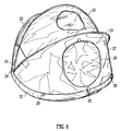
- the fabric canopy 27 is pulled from its collapsed configuration shown in Figure 7 in a direction which is perpendicular to the plane of the arches 23 to cause the arches 23 to rotate about their free ends 25 located at the common points 24, and into the erected configuration illustrated in Figure 8.
- the releasable fasteners 29 are then secured to corresponding portions of Velcro® on the fabric canopy 27 to hold it in position.
- the tent 21 may be provided with a doorway 28 which can be circular, triangular (see Figure 9) or other shape.
- FIG 10 shows the tent 21 from the opposite side shown in Figure 4. Access to the valve of the air chamber 20 is provided at 30. In this way it is possible to simply deflate the air chamber and fold the arches 23 together to fold up the tent 21 for storage.
Landscapes
- Engineering & Computer Science (AREA)
- Architecture (AREA)
- Civil Engineering (AREA)
- Structural Engineering (AREA)
- Tents Or Canopies (AREA)
Applications Claiming Priority (2)
| Application Number | Priority Date | Filing Date | Title |
|---|---|---|---|
| GB0401956A GB2410262A (en) | 2004-01-23 | 2004-01-23 | Igloo/dome tent |
| GB0401956 | 2004-01-29 |
Publications (2)
| Publication Number | Publication Date |
|---|---|
| EP1559854A2 true EP1559854A2 (fr) | 2005-08-03 |
| EP1559854A3 EP1559854A3 (fr) | 2006-07-26 |
Family
ID=31971669
Family Applications (1)
| Application Number | Title | Priority Date | Filing Date |
|---|---|---|---|
| EP05250512A Withdrawn EP1559854A3 (fr) | 2004-01-23 | 2005-01-31 | Structure repliable en toile |
Country Status (4)
| Country | Link |
|---|---|
| US (1) | US20050194028A1 (fr) |
| EP (1) | EP1559854A3 (fr) |
| CA (1) | CA2494472A1 (fr) |
| GB (1) | GB2410262A (fr) |
Cited By (2)
| Publication number | Priority date | Publication date | Assignee | Title |
|---|---|---|---|---|
| EP2275627A1 (fr) | 2009-06-19 | 2011-01-19 | Oase Outdoors APS | Tente tunnel auto-déployable et son procédé d'emballage |
| KR101669896B1 (ko) * | 2015-09-17 | 2016-10-28 | 주식회사 청광놀티르 | 놀이기구용 튜브 놀이대 |
Families Citing this family (19)
| Publication number | Priority date | Publication date | Assignee | Title |
|---|---|---|---|---|
| US7427101B1 (en) * | 2005-04-18 | 2008-09-23 | Nature Vision, Inc. | Chair shelter |
| US20070298675A1 (en) * | 2006-06-21 | 2007-12-27 | Abraham Lugo | Fixed-body toy vehicle having differential thrust and unassisted liftoff capability |
| US7712437B2 (en) * | 2006-09-18 | 2010-05-11 | Launchlab, Inc. | Mobile pet bed/carrier |
| US7814723B2 (en) * | 2006-09-25 | 2010-10-19 | Vanelverdinghe Jeffry L | Beam and truss structure for a canopy |
| GB2451651B (en) * | 2007-08-04 | 2012-02-01 | Finecard Internat Ltd | Pop up structure, primarily for use as a travel cot |
| US20120252634A1 (en) * | 2008-05-06 | 2012-10-04 | Masato Ikegami | Trampoline with collapsible enclosure assembly |
| US20100031413A1 (en) * | 2008-08-08 | 2010-02-11 | Jensen Terry L | Convertible jacket systems |
| GB2503002B (en) * | 2012-06-13 | 2016-05-25 | Southampton Solent Univ | A wearable pack comprising a portable shelter |
| RU150799U1 (ru) * | 2013-01-10 | 2015-02-27 | Тини Лав Лтд. | Детский игровой центр |
| US9011196B2 (en) | 2013-03-15 | 2015-04-21 | Global Marketing Enterprise (Gme) Ltd. | Developmental activity gym for babies |
| USD737919S1 (en) | 2014-05-07 | 2015-09-01 | Meadowbrook LLC | Children's camper play tent |
| USD833558S1 (en) | 2017-07-14 | 2018-11-13 | Kids Ii, Inc. | Play gym |
| USD881487S1 (en) * | 2017-12-20 | 2020-04-14 | Robyn Davis | Small dog pool float |
| USD886535S1 (en) * | 2018-02-02 | 2020-06-09 | Mr. Bar-B-Q Products Llc | Food basket |
| FR3087465B1 (fr) | 2018-10-22 | 2020-10-16 | Easia Travel Consulting | Tente avec structure autoportante |
| USD1008368S1 (en) * | 2019-02-21 | 2023-12-19 | Sassy Baby, Inc. | Mat for an infant |
| USD923128S1 (en) * | 2021-01-25 | 2021-06-22 | Shenzhen Create Future International Trading Company | Tent |
| US12522061B2 (en) * | 2022-06-30 | 2026-01-13 | Patrick Timothy Yerby, JR. | Inflatable vehicle cover |
| JP1766370S (ja) * | 2023-10-10 | 2024-03-25 | テント |
Citations (5)
| Publication number | Priority date | Publication date | Assignee | Title |
|---|---|---|---|---|
| US2167219A (en) | 1938-09-09 | 1939-07-25 | Sankey Elmer | Foldable tent |
| US4858634A (en) | 1988-07-18 | 1989-08-22 | Mcleese Eddie S | Self erecting structure |
| US5163461A (en) | 1991-10-17 | 1992-11-17 | Ivanovich Michael K | Self-erecting shelter |
| US5337772A (en) | 1993-04-12 | 1994-08-16 | Habchi Elie E | Self-unfolding shelter |
| US6363955B1 (en) | 2000-01-10 | 2002-04-02 | Billwin Auto Accessories, Ltd. | Self-deploying tubular enclosure |
Family Cites Families (4)
| Publication number | Priority date | Publication date | Assignee | Title |
|---|---|---|---|---|
| US4858643A (en) * | 1988-03-14 | 1989-08-22 | Unit Instruments, Inc. | Fluid flow stabilizing apparatus |
| US5059463A (en) * | 1990-03-12 | 1991-10-22 | Peters Michael V | Folding mat and shelter |
| DE4214718A1 (de) * | 1992-05-04 | 1993-11-11 | Mohl Rolf Dieter | Tragbare Sonnenschutzvorrichtung |
| US5601105A (en) * | 1996-04-08 | 1997-02-11 | Blen; Charles A. | Self-erecting tent |
-
2004
- 2004-01-23 GB GB0401956A patent/GB2410262A/en not_active Withdrawn
-
2005
- 2005-01-27 CA CA002494472A patent/CA2494472A1/fr not_active Abandoned
- 2005-01-28 US US11/045,695 patent/US20050194028A1/en not_active Abandoned
- 2005-01-31 EP EP05250512A patent/EP1559854A3/fr not_active Withdrawn
Patent Citations (5)
| Publication number | Priority date | Publication date | Assignee | Title |
|---|---|---|---|---|
| US2167219A (en) | 1938-09-09 | 1939-07-25 | Sankey Elmer | Foldable tent |
| US4858634A (en) | 1988-07-18 | 1989-08-22 | Mcleese Eddie S | Self erecting structure |
| US5163461A (en) | 1991-10-17 | 1992-11-17 | Ivanovich Michael K | Self-erecting shelter |
| US5337772A (en) | 1993-04-12 | 1994-08-16 | Habchi Elie E | Self-unfolding shelter |
| US6363955B1 (en) | 2000-01-10 | 2002-04-02 | Billwin Auto Accessories, Ltd. | Self-deploying tubular enclosure |
Cited By (2)
| Publication number | Priority date | Publication date | Assignee | Title |
|---|---|---|---|---|
| EP2275627A1 (fr) | 2009-06-19 | 2011-01-19 | Oase Outdoors APS | Tente tunnel auto-déployable et son procédé d'emballage |
| KR101669896B1 (ko) * | 2015-09-17 | 2016-10-28 | 주식회사 청광놀티르 | 놀이기구용 튜브 놀이대 |
Also Published As
| Publication number | Publication date |
|---|---|
| US20050194028A1 (en) | 2005-09-08 |
| CA2494472A1 (fr) | 2005-07-29 |
| EP1559854A3 (fr) | 2006-07-26 |
| GB2410262A (en) | 2005-07-27 |
| GB0401956D0 (en) | 2004-03-03 |
Similar Documents
| Publication | Publication Date | Title |
|---|---|---|
| EP1559854A2 (fr) | Structure repliable en toile | |
| US6604537B2 (en) | Collapsible structures | |
| US7392555B2 (en) | Bed-tent | |
| US7267625B2 (en) | Collapsible structures | |
| US6192635B1 (en) | Multipurpose collapsible panels | |
| KR100309298B1 (ko) | 자동조립식휴대용직물구조물 | |
| US7549433B2 (en) | Vertically stacked collapsible structures | |
| US20100147345A1 (en) | Collapsible structures | |
| US20040159348A1 (en) | Collapsible structures | |
| US6698441B1 (en) | Collapsible structures | |
| US7703228B2 (en) | Collapsible structures | |
| JP2001140503A (ja) | コイル状に折り曲げ自在な支持部材を備えている折り畳み式布構造体及び該構造体を折り畳む方法 | |
| US5655558A (en) | Multiple configuration tent structure | |
| US20210115694A1 (en) | Self-opening and collapsible tent structure | |
| US20090025767A1 (en) | Collapsible structures | |
| US20050103372A1 (en) | Animal umbrella |
Legal Events
| Date | Code | Title | Description |
|---|---|---|---|
| PUAI | Public reference made under article 153(3) epc to a published international application that has entered the european phase |
Free format text: ORIGINAL CODE: 0009012 |
|
| AK | Designated contracting states |
Kind code of ref document: A2 Designated state(s): AT BE BG CH CY CZ DE DK EE ES FI FR GB GR HU IE IS IT LI LT LU MC NL PL PT RO SE SI SK TR |
|
| AX | Request for extension of the european patent |
Extension state: AL BA HR LV MK YU |
|
| PUAL | Search report despatched |
Free format text: ORIGINAL CODE: 0009013 |
|
| AK | Designated contracting states |
Kind code of ref document: A3 Designated state(s): AT BE BG CH CY CZ DE DK EE ES FI FR GB GR HU IE IS IT LI LT LU MC NL PL PT RO SE SI SK TR |
|
| AX | Request for extension of the european patent |
Extension state: AL BA HR LV MK YU |
|
| AKX | Designation fees paid | ||
| REG | Reference to a national code |
Ref country code: DE Ref legal event code: 8566 |
|
| STAA | Information on the status of an ep patent application or granted ep patent |
Free format text: STATUS: THE APPLICATION IS DEEMED TO BE WITHDRAWN |
|
| 18D | Application deemed to be withdrawn |
Effective date: 20070127 |