EP1559860A2 - Méchanisme de porte pour ouverture d'accès aux marchandises dans une machine de vente automatique - Google Patents
Méchanisme de porte pour ouverture d'accès aux marchandises dans une machine de vente automatique Download PDFInfo
- Publication number
- EP1559860A2 EP1559860A2 EP05250272A EP05250272A EP1559860A2 EP 1559860 A2 EP1559860 A2 EP 1559860A2 EP 05250272 A EP05250272 A EP 05250272A EP 05250272 A EP05250272 A EP 05250272A EP 1559860 A2 EP1559860 A2 EP 1559860A2
- Authority
- EP
- European Patent Office
- Prior art keywords
- door plate
- takeout port
- commodity
- door
- commodity takeout
- Prior art date
- Legal status (The legal status is an assumption and is not a legal conclusion. Google has not performed a legal analysis and makes no representation as to the accuracy of the status listed.)
- Withdrawn
Links
Images


Classifications
-
- E—FIXED CONSTRUCTIONS
- E05—LOCKS; KEYS; WINDOW OR DOOR FITTINGS; SAFES
- E05F—DEVICES FOR MOVING WINGS INTO OPEN OR CLOSED POSITION; CHECKS FOR WINGS; WING FITTINGS NOT OTHERWISE PROVIDED FOR, CONCERNED WITH THE FUNCTIONING OF THE WING
- E05F3/00—Closers or openers with braking devices, e.g. checks; Construction of pneumatic or liquid braking devices
- E05F3/20—Closers or openers with braking devices, e.g. checks; Construction of pneumatic or liquid braking devices in hinges
-
- G—PHYSICS
- G07—CHECKING-DEVICES
- G07F—COIN-FREED OR LIKE APPARATUS
- G07F11/00—Coin-freed apparatus for dispensing, or the like, discrete articles
- G07F11/02—Coin-freed apparatus for dispensing, or the like, discrete articles from non-movable magazines
- G07F11/04—Coin-freed apparatus for dispensing, or the like, discrete articles from non-movable magazines in which magazines the articles are stored one vertically above the other
- G07F11/16—Delivery means
- G07F11/163—Delivery means characterised by blocking access to the output bins
-
- E—FIXED CONSTRUCTIONS
- E05—LOCKS; KEYS; WINDOW OR DOOR FITTINGS; SAFES
- E05F—DEVICES FOR MOVING WINGS INTO OPEN OR CLOSED POSITION; CHECKS FOR WINGS; WING FITTINGS NOT OTHERWISE PROVIDED FOR, CONCERNED WITH THE FUNCTIONING OF THE WING
- E05F1/00—Closers or openers for wings, not otherwise provided for in this subclass
- E05F1/08—Closers or openers for wings, not otherwise provided for in this subclass spring-actuated, e.g. for horizontally sliding wings
- E05F1/10—Closers or openers for wings, not otherwise provided for in this subclass spring-actuated, e.g. for horizontally sliding wings for swinging wings, e.g. counterbalance
- E05F1/12—Mechanisms in the shape of hinges or pivots, operated by springs
- E05F1/1207—Mechanisms in the shape of hinges or pivots, operated by springs with a coil spring parallel with the pivot axis
- E05F1/1223—Mechanisms in the shape of hinges or pivots, operated by springs with a coil spring parallel with the pivot axis with a compression or traction spring
-
- G—PHYSICS
- G07—CHECKING-DEVICES
- G07F—COIN-FREED OR LIKE APPARATUS
- G07F11/00—Coin-freed apparatus for dispensing, or the like, discrete articles
- G07F11/72—Auxiliary equipment, e.g. for lighting cigars, opening bottles
-
- E—FIXED CONSTRUCTIONS
- E05—LOCKS; KEYS; WINDOW OR DOOR FITTINGS; SAFES
- E05D—HINGES OR SUSPENSION DEVICES FOR DOORS, WINDOWS OR WINGS
- E05D11/00—Additional features or accessories of hinges
- E05D11/10—Devices for preventing movement between relatively-movable hinge parts
- E05D11/1014—Devices for preventing movement between relatively-movable hinge parts for maintaining the hinge in only one position, e.g. closed
-
- E—FIXED CONSTRUCTIONS
- E05—LOCKS; KEYS; WINDOW OR DOOR FITTINGS; SAFES
- E05Y—INDEXING SCHEME ASSOCIATED WITH SUBCLASSES E05D AND E05F, RELATING TO CONSTRUCTION ELEMENTS, ELECTRIC CONTROL, POWER SUPPLY, POWER SIGNAL OR TRANSMISSION, USER INTERFACES, MOUNTING OR COUPLING, DETAILS, ACCESSORIES, AUXILIARY OPERATIONS NOT OTHERWISE PROVIDED FOR, APPLICATION THEREOF
- E05Y2999/00—Subject-matter not otherwise provided for in this subclass
Definitions
- the present invention relates to a commodity takeout port in a vending machine through which commodities such as drinks in bins, cans, or PET bottles are sold.
- a known door mechanism for a commodity takeout port of a vending machine of this kind comprises a door plate having an upper end rotatively movably supported at an upper end of the commodity takeout port, the door plate being capable of opening and closing the commodity takeout port.
- the commodity takeout port is opened by manual operation, and is closed automatically.
- the door plate With the door mechanism for the commodity takeout port in the vending machine, the door plate is closed by its own weight. Consequently, the user may have his or her hand caught in the commodity takeout port when taking out a commodity, or noise may be generated when the door plate is closed.
- a known door mechanism comprises a damper that offers rotative movement resistance to the rotative movement of a support shaft supporting the door plate.
- the present invention comprises a door plate which allows a commodity takeout port to be manually opened and which can automatically close the commodity takeout port, and a damper that offers rotative movement resistance to the door plate rotatively moved in a direction in which the commodity takeout port is closed.
- the damper is provided with a cam that rotatively moves integrally with the door plate to vary the rotative movement resistance offered to the door plate depending on an opening of the door plate.
- the damper varies the rotative movement resistance to the door plate depending on the opening angle of the door plate. This makes it possible to reduce the closing speed obtained while the fully open door plate is rotatively moved in a closing direction through a predetermined opening angle and to increase the closing speed for the other opening angles. Accordingly, the user can open the door plate only with one hand, while taking out a commodity with one hand while the door plate is open. After the commodity has been taken out, the door plate can be closed without leaving the commodity takeout port open for an unnecessarily long time. This prevents the entry of dirt, dust, rainwater, or the like.
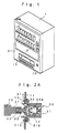
- FIGS. 1 to 5 show a first embodiment of the present invention.
- a door mechanism for a commodity takeout port in a vending machine is composed of a commodity takeout port 10 through which a user takes out a commodity, a door plate 20 having an upper end rotatively movably supported and which can open the commodity takeout port when rotatively moved forward, and a damper 30 that offers rotative movement resistance to the rotative movement of the door plate 20.
- the commodity takeout port 10 is provided by forming an opening in a lower part of an outer door 2 of a vending machine 1 in the form of a horizontally long rectangle.
- the door plate 20 consists of a horizontally long rectangular member formed of a transparent resin.
- the door plate 20 externally covers the commodity takeout port 10.
- a width-wise pair of cylindrical support shafts 21 having the same axis is formed at the top of the width-wise opposite ends of the door plate 20 integrally with the door plate 20.
- a fitting hole 22 is formed in a central portion of an end surface of one of two support shafts 21; the fitting hole 22 is fitted around a shaft 32 of the damper 30 which will be described later.
- the damper 30 comprises a housing 31 shaped like a bottomed cylinder, a shaft 32 that transmits rotative movement resistance to the door plate 20, a cam 33 that varies the rotative movement resistance offered to the door plate 20, a piston 34 that can slide through the housing 31, and a guide pin 35 serving as an abutting member assembled on the piston 34.
- the housing 31 is provided with a pair of mounting flanges 31a on an outer surface.
- a screw through-hole 31b is formed in each of the mounting flanges 31a.
- the housing 31 is mounted at one end of each of two support plates 11 provided at laterally opposite ends in the commodity takeout port 10 using the mounting flanges 31a, the support plates 11 being extended in a vertical direction.
- the shaft 32 has one end connected to the support shaft 21 of the door plate 20.
- the shaft 32 rotatively moves with the support shaft 21 when the door plate 20 is opened and closed. Further, the other end of the shaft 32 is fixed to one end surface of the cam 33.
- the shaft 32 and the cam 33 are integrated together.
- the one end surface of the cam 33 is fixed to the other end of the shaft 32.
- An abutting surface 33a is formed on the other end surface of the cam 33 in a circumferential direction; the guide pin 35 abuts against the other end of the cam 33.
- the abutting surface 33a is formed by obliquely cutting the one end surface of the cam 33.
- the abutting surface 33a has an angle of inclination corresponding to rotative movement resistance offered to the door plate 20.
- the piston 34 is slidably housed inside the housing 31.
- the guide pin 35 is provided on one end surface of the piston 34.
- a spring 34a abuts against the other end surface of the piston 34 to urge the piston 34 toward the cam 33; the spring 34a is provided between the housing 31 and the piston 34 as an urging member.
- the guide pin 35 is provided on the one end surface of the piston 34 so as to extend perpendicularly to an axial direction of the piston 34.
- the guide pin 35 abuts against the abutting surface 33a.
- the cam 33 rotatively moves as the abutting surface 33a slidably moves with respect to the guide pin 35 against the urging force of the spring 34a.
- the abutting surface 33a of the cam 33 which rotatively moves with respect to the guide pin 35, is formed to have a large angle of inclination between the point P and a point R. Consequently, a large rotative movement resistance is offered to the closing operation of the door plate 20.
- the inclination of the abutting surface 33a is formed so that about three seconds are required to close the door plate 20 from an opening angle of 135° to an opening angle of 125°. Further, as shown in FIG.
- the angle of inclination of the abutting surface 33a of the cam 33 which rotatively moves with respect to the guide pin 35, is formed to have a smaller angle of inclination between the point R and a point Q than between the points P and R. This prevents a large rotative movement resistance from being offered to the closing operation of the door plate 20. As a result, the door plate 20 is completely closed.
- the rotative movement resistance is varied depending on the opening angle of the door plate 20. This makes it possible to reduce the closing speed obtained while the fully open door plate 20 is rotatively moved in a closing direction through a predetermined opening angle and to increase the closing speed for the other opening angles. Accordingly, the user can open the door plate 20 with one hand, while taking out a commodity with one hand while the door plate 20 is open. The door plate 20 can thus be closed without leaving the commodity takeout port 10 open for an unnecessarily long time. This prevents the entry of dirt, dust, rainwater, or the like.
- the damper 30 is composed of the cam 33, which rotatively moves with the support shaft 21 of the door plate 20, the guide pin 35, which abuts against the abutting surface 33a, and the spring 34a, which urges the guide pin 35 toward the cam 33.
- This allows the rotative movement resistance offered to the door plate 20 to be changed by changing the angle of inclination of the abutting surface 33a. Consequently, the rotative movement resistance offered to the door plate 20 can be easily set as required.
- the abutting surface 33a is formed so as to reduce the rotative movement resistance offered to the door plate 20 as the door plate 20 is closed. This enables the door plate 20 to be closed immediately after the commodity has been taken out. The door plate 20 can thus be closed without leaving the commodity takeout port 10 open for an unnecessarily long time. This prevents the entry of dirt, dust, rainwater, or the like.
- the abutting surface 33a is formed so as to offer the predetermined rotative movement resistance to the support shaft 21 of the door plate 20 while the fully open door plate 20 is rotatively moved in the closing direction through the predetermined angle and to reduce the rotative movement resistance offered to the support shaft 21 of the door plate 20 after the fully open door plate 20 has been rotatively moved in the closing direction through the predetermined angle.
- This makes it possible to reduce the closing speed obtained while the fully open door plate 20 is rotatively moved through the predetermined opening angle and to increase the closing speed of the door plate 20 for the other opening angles. Accordingly, the user can open the door plate 20 with one hand, while taking out a commodity with one hand while the door plate 20 is open.
- the door plate 20 can thus be closed without leaving the commodity takeout port 10 open for an unnecessarily long time. This prevents the entry of dirt, dust, rainwater, or the like.
- the abutting surface 33a is formed so that about three seconds are required to close the fully open door plate 20 through an angle of 10°. This enables the door plate 20 to be kept open for at least about three seconds after the door plate 20 has been opened. Therefore, when opening the door plate 20 to take out a commodity, the user can easily take it out without having his or her hand caught in the commodity takeout port 10.
- the commodity takeout port 10 is opened by rotatively moving the door plate 20 forward from the commodity takeout port 10. This enables the commodity takeout port 10 to be externally covered. It is therefore possible to prevent the entry of dirt, dust, rainwater, or the like.
- the support shaft 21 and the shaft 32 are fixed to each other by inserting the shaft 32 into the shaft 21.
- the shaft 32 may be formed to be cylindrical so that the support shaft 21 and the shaft 32 can be fixed to each other by inserting the support shaft 21 around the shaft 32.
- the large rotative movement resistance is offered to the door plate 20 while the fully open door plate 20 is rotatively moved in the closing direction through the predetermined angle. Then, the rotative movement resistance offered to the door plate 20 is reduced after the fully open door plate 20 has been rotatively moved in the closing direction through at least the predetermined angle.
- the rotative movement resistance offered to the support shaft 21 of the door plate 20 may be reduced while the fully open door plate 20 is rotatively moved in the closing direction through the predetermined angle. Then, the rotative movement resistance offered to the door plate 20 is increased after the fully open door plate 20 has been rotatively moved in the closing direction through at least the predetermined angle. In this case, a rotative movement speed can be reduced when the door plate 20 is completely closed. This serves to reduce a shock sound generated when the door plate 20 collides against a part of the outer door 2 which is located below the commodity takeout port 10.
- FIG. 6 shows a second embodiment of the present invention.
- the same reference numerals are used for components of the second embodiment which are similar to those of the first embodiment.
- the door, mechanism for the commodity takeout port in the vending machine is configured so that a door plate 40 has an upper end rotatively movably supported and is rotatively moved backward to open the commodity takeout port 10.
- a width-wise pair of cylindrical support shafts 41 having the same axis is formed at the top of the width-wise opposite ends of the door plate 40 integrally with the door plate 40.
- a fitting hole 42 is formed in a central portion of an end surface of one of two support shafts 41; the fitting hole 42 is fitted around the shaft 32 of the damper 30.
- the cam 33 rotatively moves together with the shaft 32.
- the guide pin 35 is urged toward the shaft 32 side of the abutting surface 33a by the urging force of the spring 34a.
- the guide pin 35 is then positioned at the point P of the abutting surface 33a.
- the door plate 40 starts to close owing to its own weight.
- the cam 33 rotatively moves as the abutting surface 33a slidably moves with respect to the guide pin 35 against the urging force of the spring 34a.
- the abutting surface 33a of the cam 33 which rotatively moves with respect to the guide pin 35, is formed to have a large angle of inclination between the points P and R. Consequently, a large rotative movement resistance is offered to the closing operation of the door plate 40.
- the inclination of the abutting surface 33a is formed so that about three seconds are required to close the door plate 40 from an opening angle of 84° to an opening angle of 74°.
- the angle of inclination of the abutting surface 33a of the cam 33 which rotatively moves with respect to the guide pin 35, is formed to have a smaller angle of inclination between the points R and Q than between the points P and R. This prevents a large rotative movement resistance from being offered to the closing operation of the door plate 40. As a result, the door plate 40 is completely closed.
- the commodity takeout port 10 is opened by rotatively moving the door plate 40 backward from the commodity takeout port 10. Consequently, the commodity takeout port 10 can be opened by rotatively moving the door plate 40 backward. This prevents the door plate 40 from being extended from a front surface of the commodity takeout port 10. Therefore, commodities can be further easily taken out.
Landscapes
- Physics & Mathematics (AREA)
- General Physics & Mathematics (AREA)
- Control Of Vending Devices And Auxiliary Devices For Vending Devices (AREA)
Applications Claiming Priority (2)
| Application Number | Priority Date | Filing Date | Title |
|---|---|---|---|
| JP2004021809 | 2004-01-29 | ||
| JP2004021809A JP2004303200A (ja) | 2003-03-18 | 2004-01-29 | 自動販売機における商品取出口の扉機構 |
Publications (2)
| Publication Number | Publication Date |
|---|---|
| EP1559860A2 true EP1559860A2 (fr) | 2005-08-03 |
| EP1559860A3 EP1559860A3 (fr) | 2006-07-05 |
Family
ID=34650829
Family Applications (1)
| Application Number | Title | Priority Date | Filing Date |
|---|---|---|---|
| EP05250272A Withdrawn EP1559860A3 (fr) | 2004-01-29 | 2005-01-20 | Méchanisme de porte pour ouverture d'accès aux marchandises dans une machine de vente automatique |
Country Status (2)
| Country | Link |
|---|---|
| EP (1) | EP1559860A3 (fr) |
| CN (1) | CN1648955A (fr) |
Families Citing this family (1)
| Publication number | Priority date | Publication date | Assignee | Title |
|---|---|---|---|---|
| CN102610036A (zh) * | 2012-03-27 | 2012-07-25 | 无锡可易得自动售货系统科技有限公司 | 自动售货机 |
Family Cites Families (3)
| Publication number | Priority date | Publication date | Assignee | Title |
|---|---|---|---|---|
| JPH10131947A (ja) * | 1996-10-28 | 1998-05-22 | Kato Electrical Mach Co Ltd | 複合トルクヒンジ |
| JP3053584B2 (ja) * | 1997-01-20 | 2000-06-19 | トックベアリング株式会社 | 自動販売機の商品取出口用蓋の緩衝装置 |
| JP2000306149A (ja) * | 1999-04-22 | 2000-11-02 | Sanden Corp | 自動販売機の商品取出口扉 |
-
2005
- 2005-01-20 EP EP05250272A patent/EP1559860A3/fr not_active Withdrawn
- 2005-01-28 CN CNA2005100063637A patent/CN1648955A/zh active Pending
Also Published As
| Publication number | Publication date |
|---|---|
| EP1559860A3 (fr) | 2006-07-05 |
| CN1648955A (zh) | 2005-08-03 |
Similar Documents
| Publication | Publication Date | Title |
|---|---|---|
| US10280671B2 (en) | Furniture hinge comprising a damper and a spring | |
| US7906921B2 (en) | Induction actuated container | |
| JP6815018B2 (ja) | 摺動ドアのためのガイドデバイス | |
| US5901415A (en) | Dual pivot hinge assembly | |
| US6463627B1 (en) | Lid stay with a first and second arm pivotally connected to the first arm | |
| EP2468999A1 (fr) | Système d ouverture/fermeture de porte et fermeture associée | |
| US8701248B2 (en) | Door construction with closing pivot hinges integrated into door panel | |
| US20120056063A1 (en) | Cup holder | |
| US20090083939A1 (en) | Damper device for retarding pivotal advancement of a hinged wall piece towards a hinging wall piece | |
| JP5150208B2 (ja) | 扉開閉装置 | |
| US20170122020A1 (en) | Appliance lid hinge assembly with snubber | |
| CA2771496A1 (fr) | Dispositif pour regler la position d'un amortisseur | |
| US20160324367A1 (en) | Damper mechanism for tilt-head stand mixer | |
| US20070209654A1 (en) | Hinge device of a steam oven door | |
| US7464625B2 (en) | Apparatus for opening and closing a door of a container apparatus of a vehicle | |
| SE519509C2 (sv) | Luckstängningsanordning | |
| JP4825236B2 (ja) | ダンパ付きスライドヒンジ | |
| JP4440930B2 (ja) | 扉開閉装置 | |
| US20060070995A1 (en) | Upper cover of a garbage can | |
| CN111197442B (zh) | 用于车辆的储物舱 | |
| US7162775B2 (en) | Boot cover hinge | |
| JPH08312236A (ja) | 貯蔵庫 | |
| US11542739B1 (en) | Door closer mechanism | |
| KR102029312B1 (ko) | 댐핑힌지 | |
| JP2004303200A (ja) | 自動販売機における商品取出口の扉機構 |
Legal Events
| Date | Code | Title | Description |
|---|---|---|---|
| PUAI | Public reference made under article 153(3) epc to a published international application that has entered the european phase |
Free format text: ORIGINAL CODE: 0009012 |
|
| AK | Designated contracting states |
Kind code of ref document: A2 Designated state(s): AT BE BG CH CY CZ DE DK EE ES FI FR GB GR HU IE IS IT LI LT LU MC NL PL PT RO SE SI SK TR |
|
| AX | Request for extension of the european patent |
Extension state: AL BA HR LV MK YU |
|
| PUAL | Search report despatched |
Free format text: ORIGINAL CODE: 0009013 |
|
| AK | Designated contracting states |
Kind code of ref document: A3 Designated state(s): AT BE BG CH CY CZ DE DK EE ES FI FR GB GR HU IE IS IT LI LT LU MC NL PL PT RO SE SI SK TR |
|
| AX | Request for extension of the european patent |
Extension state: AL BA HR LV MK YU |
|
| RIC1 | Information provided on ipc code assigned before grant |
Ipc: G07F 9/00 20060101ALI20060529BHEP Ipc: E05F 1/12 20060101AFI20060529BHEP |
|
| AKX | Designation fees paid | ||
| REG | Reference to a national code |
Ref country code: DE Ref legal event code: 8566 |
|
| STAA | Information on the status of an ep patent application or granted ep patent |
Free format text: STATUS: THE APPLICATION IS DEEMED TO BE WITHDRAWN |
|
| 18D | Application deemed to be withdrawn |
Effective date: 20061204 |