EP1559882B1 - Dispositif de purification des gaz d'échappement et procédé de fabrication d'un dispositif de purification des gaz d'échappement - Google Patents
Dispositif de purification des gaz d'échappement et procédé de fabrication d'un dispositif de purification des gaz d'échappement Download PDFInfo
- Publication number
- EP1559882B1 EP1559882B1 EP05001368A EP05001368A EP1559882B1 EP 1559882 B1 EP1559882 B1 EP 1559882B1 EP 05001368 A EP05001368 A EP 05001368A EP 05001368 A EP05001368 A EP 05001368A EP 1559882 B1 EP1559882 B1 EP 1559882B1
- Authority
- EP
- European Patent Office
- Prior art keywords
- exhaust gas
- plates
- gas purification
- arrangement according
- purification arrangement
- Prior art date
- Legal status (The legal status is an assumption and is not a legal conclusion. Google has not performed a legal analysis and makes no representation as to the accuracy of the status listed.)
- Expired - Lifetime
Links
Images


Classifications
-
- F—MECHANICAL ENGINEERING; LIGHTING; HEATING; WEAPONS; BLASTING
- F01—MACHINES OR ENGINES IN GENERAL; ENGINE PLANTS IN GENERAL; STEAM ENGINES
- F01N—GAS-FLOW SILENCERS OR EXHAUST APPARATUS FOR MACHINES OR ENGINES IN GENERAL; GAS-FLOW SILENCERS OR EXHAUST APPARATUS FOR INTERNAL-COMBUSTION ENGINES
- F01N3/00—Exhaust or silencing apparatus having means for purifying, rendering innocuous, or otherwise treating exhaust
- F01N3/08—Exhaust or silencing apparatus having means for purifying, rendering innocuous, or otherwise treating exhaust for rendering innocuous
- F01N3/10—Exhaust or silencing apparatus having means for purifying, rendering innocuous, or otherwise treating exhaust for rendering innocuous by thermal or catalytic conversion of noxious components of exhaust
- F01N3/24—Exhaust or silencing apparatus having means for purifying, rendering innocuous, or otherwise treating exhaust for rendering innocuous by thermal or catalytic conversion of noxious components of exhaust characterised by constructional aspects of converting apparatus
- F01N3/28—Construction of catalytic reactors
- F01N3/2803—Construction of catalytic reactors characterised by structure, by material or by manufacturing of catalyst support
- F01N3/2807—Metal other than sintered metal
- F01N3/281—Metallic honeycomb monoliths made of stacked or rolled sheets, foils or plates
-
- F—MECHANICAL ENGINEERING; LIGHTING; HEATING; WEAPONS; BLASTING
- F01—MACHINES OR ENGINES IN GENERAL; ENGINE PLANTS IN GENERAL; STEAM ENGINES
- F01N—GAS-FLOW SILENCERS OR EXHAUST APPARATUS FOR MACHINES OR ENGINES IN GENERAL; GAS-FLOW SILENCERS OR EXHAUST APPARATUS FOR INTERNAL-COMBUSTION ENGINES
- F01N3/00—Exhaust or silencing apparatus having means for purifying, rendering innocuous, or otherwise treating exhaust
- F01N3/08—Exhaust or silencing apparatus having means for purifying, rendering innocuous, or otherwise treating exhaust for rendering innocuous
- F01N3/10—Exhaust or silencing apparatus having means for purifying, rendering innocuous, or otherwise treating exhaust for rendering innocuous by thermal or catalytic conversion of noxious components of exhaust
- F01N3/24—Exhaust or silencing apparatus having means for purifying, rendering innocuous, or otherwise treating exhaust for rendering innocuous by thermal or catalytic conversion of noxious components of exhaust characterised by constructional aspects of converting apparatus
- F01N3/28—Construction of catalytic reactors
- F01N3/2803—Construction of catalytic reactors characterised by structure, by material or by manufacturing of catalyst support
- F01N3/2807—Metal other than sintered metal
- F01N3/281—Metallic honeycomb monoliths made of stacked or rolled sheets, foils or plates
- F01N3/2814—Metallic honeycomb monoliths made of stacked or rolled sheets, foils or plates all sheets, plates or foils being corrugated
-
- F—MECHANICAL ENGINEERING; LIGHTING; HEATING; WEAPONS; BLASTING
- F01—MACHINES OR ENGINES IN GENERAL; ENGINE PLANTS IN GENERAL; STEAM ENGINES
- F01N—GAS-FLOW SILENCERS OR EXHAUST APPARATUS FOR MACHINES OR ENGINES IN GENERAL; GAS-FLOW SILENCERS OR EXHAUST APPARATUS FOR INTERNAL-COMBUSTION ENGINES
- F01N3/00—Exhaust or silencing apparatus having means for purifying, rendering innocuous, or otherwise treating exhaust
- F01N3/08—Exhaust or silencing apparatus having means for purifying, rendering innocuous, or otherwise treating exhaust for rendering innocuous
- F01N3/10—Exhaust or silencing apparatus having means for purifying, rendering innocuous, or otherwise treating exhaust for rendering innocuous by thermal or catalytic conversion of noxious components of exhaust
- F01N3/24—Exhaust or silencing apparatus having means for purifying, rendering innocuous, or otherwise treating exhaust for rendering innocuous by thermal or catalytic conversion of noxious components of exhaust characterised by constructional aspects of converting apparatus
- F01N3/28—Construction of catalytic reactors
- F01N3/2803—Construction of catalytic reactors characterised by structure, by material or by manufacturing of catalyst support
- F01N3/2807—Metal other than sintered metal
- F01N3/281—Metallic honeycomb monoliths made of stacked or rolled sheets, foils or plates
- F01N3/2821—Metallic honeycomb monoliths made of stacked or rolled sheets, foils or plates the support being provided with means to enhance the mixing process inside the converter, e.g. sheets, plates or foils with protrusions or projections to create turbulence
-
- B—PERFORMING OPERATIONS; TRANSPORTING
- B01—PHYSICAL OR CHEMICAL PROCESSES OR APPARATUS IN GENERAL
- B01J—CHEMICAL OR PHYSICAL PROCESSES, e.g. CATALYSIS OR COLLOID CHEMISTRY; THEIR RELEVANT APPARATUS
- B01J35/00—Catalysts, in general, characterised by their form or physical properties
- B01J35/50—Catalysts, in general, characterised by their form or physical properties characterised by their shape or configuration
- B01J35/56—Foraminous structures having flow-through passages or channels, e.g. grids or three-dimensional [3D] monoliths
-
- F—MECHANICAL ENGINEERING; LIGHTING; HEATING; WEAPONS; BLASTING
- F01—MACHINES OR ENGINES IN GENERAL; ENGINE PLANTS IN GENERAL; STEAM ENGINES
- F01N—GAS-FLOW SILENCERS OR EXHAUST APPARATUS FOR MACHINES OR ENGINES IN GENERAL; GAS-FLOW SILENCERS OR EXHAUST APPARATUS FOR INTERNAL-COMBUSTION ENGINES
- F01N2330/00—Structure of catalyst support or particle filter
- F01N2330/02—Metallic plates or honeycombs, e.g. superposed or rolled-up corrugated or otherwise deformed sheet metal
-
- F—MECHANICAL ENGINEERING; LIGHTING; HEATING; WEAPONS; BLASTING
- F01—MACHINES OR ENGINES IN GENERAL; ENGINE PLANTS IN GENERAL; STEAM ENGINES
- F01N—GAS-FLOW SILENCERS OR EXHAUST APPARATUS FOR MACHINES OR ENGINES IN GENERAL; GAS-FLOW SILENCERS OR EXHAUST APPARATUS FOR INTERNAL-COMBUSTION ENGINES
- F01N2330/00—Structure of catalyst support or particle filter
- F01N2330/02—Metallic plates or honeycombs, e.g. superposed or rolled-up corrugated or otherwise deformed sheet metal
- F01N2330/04—Methods of manufacturing
-
- F—MECHANICAL ENGINEERING; LIGHTING; HEATING; WEAPONS; BLASTING
- F01—MACHINES OR ENGINES IN GENERAL; ENGINE PLANTS IN GENERAL; STEAM ENGINES
- F01N—GAS-FLOW SILENCERS OR EXHAUST APPARATUS FOR MACHINES OR ENGINES IN GENERAL; GAS-FLOW SILENCERS OR EXHAUST APPARATUS FOR INTERNAL-COMBUSTION ENGINES
- F01N2330/00—Structure of catalyst support or particle filter
- F01N2330/30—Honeycomb supports characterised by their structural details
- F01N2330/32—Honeycomb supports characterised by their structural details characterised by the shape, form or number of corrugations of plates, sheets or foils
Definitions
- the present invention relates to an exhaust gas purification device and a method for manufacturing an exhaust gas purification device for purifying an exhaust gas of an internal combustion engine.
- pollutants include in particular so-called solid particles, such as. As soot particles which are harmful to the human organism. As is also known, these soot particles are ejected in particular by diesel-fueled internal combustion engines.
- an exhaust gas cleaning arrangement ie a so-called particulate filter is used, which is arranged in the exhaust system of an internal combustion engine. It is conceivable that the exhaust gas purification arrangement also has catalytic properties to convert CO emitted from the internal combustion engine CO, hydrocarbons HC and nitrogen oxides NO x into the harmless substances H 2 O, CO 2 , and N 2 . In this case, a use of the exhaust gas purification arrangement as a particle filter can not be clearly separated from a use of the exhaust gas purification system as a catalyst.
- JP 1030651 discloses a possible configuration of a catalyst carrier.
- particulate filter such that it against mechanical loads, such as generated by the internal combustion engine Exhaust pulsations, is particularly stable, and achieved a high emission control effect.
- An advantage of the present invention is that, due to the increased common contact areas between immediately adjacent plates, as opposed to contact points, a stable stack arrangement of all Plates is generated together, ie movement of the plates against each other is avoided. Thus, a material abrasion between the plates, as occurs in punctiform contact, avoided.
- the surface areas of the plates can be arbitrarily shaped or curved, for example in a two-dimensional regular arrangement, such as waves.
- Particle filtering is achieved by depositing the particles in the exhaust gas against the plate walls as the exhaust gas flows along the exhaust gas flow channels and is forced to make constant changes in direction due to the curved structure of the plates. That When the direction changes on a curved plate area, the particles hit a plate wall and can stick there.
- At least one of the two adjacent plates has a corrugated plate structure such that wave crests and wave troughs are formed alternately along substantially straight lines. Due to the corrugated structure, the plate acquires stability in itself, and thereby also the stack composed of the plurality of corrugated plates, which forms the particle filter.
- the contact surfaces of the at least one plate are arranged at least in regions at a smaller distance from the main plane than along the lines between the contact surfaces of adjacent regions of the at least one plate.
- the wave crests and the wave troughs of the two material layers adjacent to each other in the stack are oriented at an angle of more than 10 ° to one another.
- a particularly pronounced change in direction of the exhaust gas between the material layers is achieved, which leads to a more effective particle separation.
- a material of the plates is a metal sheet, which is well deformable and has a high stability in itself.
- the plates are formed from a permeable porous material for the exhaust gas.
- a porous material for the plates has the advantage that a particle deposition now takes place on the one hand by the overflow of the exhaust gas of the plates, on the other hand, the exhaust gas can flow through the porous plates and thereby filtered because particles from the exhaust gas when passing through the porous Plates can get stuck.
- the flow-through occurs due to pressure differences between the exhaust-facing surfaces of the porous plates (so-called windward sides) and the exhaust surfaces facing away from the porous plates (so-called leeward sides).
- the plates bounding the exhaust gas flow channel on its exhaust gas outlet side or on its exhaust gas inlet side adjoin one another on the outlet side or on the inlet side along a line transversely to the flow direction.
- exhaust gas flow channels are quasi closed alternately at their inlet side and at their outlet side, whereby the exhaust gas forced to pass through the porous plates and the exhaust filter effect is further increased.
- the plates bounding the exhaust gas flow channel on its outlet side or on its inlet side abut each other on the outlet side or on the inlet side along a line transversely to the flow direction. This facilitates the closing of exhaust gas flow channels on the inlet and outlet sides.
- the plates bounding the exhaust gas flow channel on its outlet side or on its inlet side are connected along the line by gluing or / and by welding or / and by folding. These types of connections are a particularly simple and efficient way to close the exhaust flow channels at the inlet and outlet side.
- the plates delimiting the exhaust gas flow channel which is closed on its outlet side or on its inlet side are connected to one another on the outlet side or on the inlet side by a continuous web extending transversely to the flow direction.
- the plates delimiting the exhaust flow channel closed on its outlet side or on its inlet side are integrally connected to one another on the outlet side or on the inlet side. This is a particularly efficient way to close the exhaust flow channels at inlet and outlet sides.
- a major plane spacing between each two adjacent plates in the stack has a value in a range of 0.5 mm to 8.0 mm, in particular 1.0 mm to 4.0 mm, and more preferably 1.5 to 3.0 mm, on.
- the main plane spacing between adjacent plates is the distance between (imaginary) middle planes of the plates.
- a deflection of the wave crests or wave troughs from the main planes is preferably greater than 1 mm.
- a deflection of the wave crests or wave troughs from their main planes is less than 7 mm, in particular less than 5 mm and more preferably less than 3 mm.
- a lateral distance in the direction of plate extension between adjacent wave crests or troughs is greater than 2 mm, in particular greater than 3 mm.
- a distance in the direction of plate extension between adjacent wave crests or troughs is less than 7 mm, in particular less than 5 mm.
- a thickness of the plates is greater than 0.1 mm, in particular greater than 0.3 mm.
- a thickness of the plates is preferably less than 2.0 mm, in particular less than 1.2 mm.
- the permeable to the exhaust gas porous material is made as a fabric and / or a nonwoven fabric and / or a braid of a fiber material.
- the fiber material comprises metal fibers and / or ceramic fibers.
- the permeable to the exhaust gas porous material is made of a powder material.
- the permeable porous material for the exhaust gas is made of a foam.
- the porous material permeable to the exhaust gas is manufactured as a sintered body.
- a fiber material or fabric as a base or carrier, which is coated with a sintered metallic or ceramic powder material.
- the permeable porous material for the exhaust gas comprises a catalyst material, in particular of at least one noble metal and / or at least one metal oxide and / or at least one mixed oxide, and / or the porous material comprises an oxygen storage material, which in particular cerium or / and a cerium oxide.
- the exhaust gas purification device can also be used as a catalyst to convert pollutants HC, CO, and NO x emitted by the internal combustion engine during operation into the harmless substances H 2 O, CO 2 , and N 2 using suitable catalyst materials. In this case, on and / or deposited in the porous material layers soot is burned under catalytic action of the catalyst material.
- the use of the exhaust gas purification arrangement is particularly advantageous in connection with the catalytic coating, ie a regeneration of the exhaust gas purification arrangement is due to the uniform flow through the exhaust gas purification system especially effective due to the convex and concave surface areas. Larger soot deposits do not arise due to the special flow, the catalytic material can effectively convert the pollutants.
- the stack is delimited on its outer side in a region between the inlet side and the outlet side of at least one mat of the fiber material and / or at least one fiber fleece layer.
- the fiber material mat completely surrounds the stack in the region between the inlet side and the outlet side.
- the present invention includes a method of manufacturing an exhaust gas purifying assembly for purifying an exhaust gas of an internal combustion engine, the method comprising the steps of: providing a web of material; Forming the strip of material by means of embossing rolls into a corrugated strip of material, wherein wave crests and wave troughs are alternately formed in the strip of material along substantially rectilinear lines, and the crests and / or troughs are formed in sections in the direction of extent of the corrugated strip of material having deformation areas in which the deformation regions are arranged in at least one material band section at least in regions at a smaller distance from a main plane of the corrugated material band than along the lines between adjacent deformation regions, so that after folding the material band to fold lines extending transversely to an extension direction of the material band, which folds with a Distance in the direction of extent of the material band from each other are arranged, and after laying the folded strip of material in sections one above the other such that a stack is formed, two adjacent stack
- a material of the material strip is a permeable porous material for the exhaust gas to be cleaned.
- the stack in the housing is oriented such that the fold lines are arranged on the stack to the inlet opening and to the outlet opening indicative, and that the stack relative to the housing is sealed so that substantially every possible way of the exhaust gas from the inlet opening to the outlet opening passes through the material band at least once.
- the material strip is guided along the fold lines during folding between two embossing rollers for introducing deformation regions.
- the deformation areas facilitate the folding of the layer in a special way.
- the deformation regions are preferably introduced by pressing the material strip into a at least one longitudinal recess provided on a first of the two rolls by means of a corresponding at least one longitudinal bead provided on a second of the two rolls.
- the at least one longitudinal recess extends parallel to an axis of the first roller and the at least one bead extends parallel to an axis of the second roller.
- corrugations and recesses adjacent to a surface of the first and second rolls are provided in the circumferential direction of the roll for corrugating the strip of material, which beads extend in a spiral around the axes of the rolls.
- an even number of circumferential regions are provided on each of the first and second rolls, which are bounded in the circumferential direction on the one hand by a longitudinal ridge and on the other by a longitudinal recess, and orientations of the spiral ridges and recesses adjacent one another in the circumferential direction Peripheral areas are opposite to each other.
- a mat of a wire mesh material and / or wire nonwoven material and / or a ceramic material and / or a ceramic fiber material is inserted between the housing and the stack.
- this arrangement in addition to the lateral sealing of the exhaust gas flow channels through the fiber material mat, the exhaust gas cleaning arrangement also at the same time in a simple manner by jamming the exhaust gas purification arrangement with the fiber material mat in the housing, without a mating connection is required.
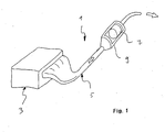
- an exhaust gas purification system 1 is shown schematically, as it is typically used for example in passenger cars.
- This exhaust gas purification system 1 is used to treat exhaust gases of a symbolically illustrated internal combustion engine 3, wherein the exhaust gas produced by the internal combustion engine 3 is discharged via an exhaust line 5 to the environment, and wherein the exhaust line 5 comprises an exhaust gas purification device or a particulate filter 7, which in a flowed through by the exhaust Housing 9 is arranged.
- the particulate filter treated in this invention in particular diesel-fueled internal combustion engines are particularly suitable.
- a catalyst (not shown here), preferably an oxidation catalyst, may be arranged in the same housing 9 for the pre- or after-treatment of the exhaust gas before or behind the particle filter 7.
- the catalyst at temperatures above about 150 ° C to 200 ° C, the hydrocarbons and carbon monoxide are oxidized.
- the task of the particulate filter is then to retain exhaust gas particles remaining in the exhaust gas through the particulate filter 7.
- FIG. 2 shows a cross-sectional view of the particle filter 7 shown schematically in FIG. 1.
- the particle filter 7 is shown installed in the housing 9, the particle filter 7 being fixed with a fiber mat 11 against slippage, i. is clamped against the housing 9, and is surrounded for protection against vibration.
- the particle filter 7 is composed of a plurality of corrugated plates 13 to a stack 15, wherein the corrugation of each plate 13 in cross section considered a quasi-sinusoidal Has course with wave crests and troughs.
- each corrugated plate has peaks of the wave crests of each corrugated plate, resulting in enlarged areas of contact 17 in the dents.
- the corrugated plates 13 are now arranged one above the other so that the wave troughs, which also have contact surfaces 17 'come to rest with their contact surfaces 17' on the contact surfaces 17 in the dents of the wave crests.
- a maximum extent of the contact surfaces is 17, 17 'D.
- a distance between two immediately adjacent plates 13, i. a spacing between major planes 19, 19 '(shown as dashed lines) is A.
- the major planes 19, 19' extend substantially centrally through the cross section of each plate 13.
- the dimensioning of D and A is chosen in the example shown in FIG. that a ratio D / A is about 0.7.
- a particularly stable arrangement of the stack 15 is achieved, i. the plates 13 can not be displaced with respect to each other in the direction of plate extension (e.g., in the case of exhaust gas pulsations), since the plates 13 engage with each other at the contact surfaces 17, 17 '.
- This effect is further enhanced by surrounding the stack 15 with the fiber mat 11 and jamming the stack 15 in the housing 9.
- other combinations of D and A are also conceivable for the ratio of D / A.
- Two immediately adjacent plates 13 delimit exhaust gas flow channels 21. That is, the exhaust gas flows along these channels 21, and in particular is forced by the corrugated structure of the plates 13 to constant (so to speak corkscrew-like) changes in direction, wherein the exhaust gas comes into contact with walls of the corrugated plates.
- the catalyst material converts the pollutants HC and CO (the exhaust gas) discharged from the internal combustion engine into the harmless substances H 2 O and CO 2 using the same catalyst material as the pollutants contact the walls of the corrugated plates as the exhaust gas flow passages flow through comes. Moreover, the reaction of NO to NO 2 is supported, wherein NO 2 supports an oxidation of carbon and carbon black at low temperatures.
- CRT-principle Continuously Regenerating Trap, continuously regenerating filter
- the exhaust gas flow is characterized by, as already mentioned above, constant change of direction , This results in a fast turbulence and homogeneous expansion of the exhaust gas in the particulate filter 7, resulting in a homogeneous operating temperature of the particulate filter 7 (thus driven internal combustion engine) and thus homogeneous or constant temperature conditions for the exhaust gas purification and regeneration of the particulate filter. 7
- FIG. 3 shows a further exhaust gas purification arrangement in an exploded perspective view of a particle filter 7a constructed from corrugated plates 13a.
- the corrugation of the plates 13a in the form of wave crests and wave troughs is formed, which, in contrast to the wave crests and troughs shown in Figure 2, along straight extending lines 20 and 20 'are arranged.
- the advantage of linearly extending wave crests and wave troughs is an increased stability of the corrugated plates 13a in them and thus an increased stability of a stack 15a composed of corrugated plates 13a.
- contact surfaces 17a can be seen, which are, so to speak, indentations on the wave crests of the wave crests along the lines 20 at regular intervals.
- the dashed lines 23 indicate the course of the wave troughs of each directly overlying plate 13a, when the plates 13a are stacked.
- the plates 13a are made of thin porous material with a catalyst material coating.
- FIG. 3a shows a detail of the particle filter 7a shown in FIG. 3 with plates 13a formed of porous material with contact surfaces 17a.
- an arrow P shows a course of the exhaust gas flow as it results for an exhaust gas purification arrangement according to FIG. 3. It can be seen that the exhaust gas flows in a corkscrew-like movement between the plates 13a, 13a, wherein the exhaust gas flows over the surfaces of the plates 13a, 13a and thereby the particles are deposited on the plate walls.
- FIG. 4 shows a further exhaust gas purification arrangement in a perspective exploded view of a particle filter 7b constructed from a stack 15b of corrugated plates 13b, 13b '.
- the corrugated plates 13b have contact surfaces 17b as dents in both the wave crests and in the troughs. Between each two plates 13b now plates 13b 'are arranged, which have no dents, so that wave crests and troughs of the plate 13b' come to rest in the dents of the immediately adjacent plates 13b, 13b.
- FIG. 5 shows a further exhaust gas purification arrangement in an exploded perspective view of a particle filter 7c constructed from corrugated plates 13c to form a stack 15c.
- each corrugated plate 13c, 13c, 13c contact surfaces 17c as dents in wave crests and troughs of the corrugated plates 13c, 13c, 13c, so that each contact surfaces in troughs of a plate with contact surfaces in wave crests of another immediately below plate are engaged.
- a particularly stable arrangement of the corrugated plates 13c is achieved.
- FIG. 6 shows a further exhaust gas purification arrangement in a sectional view of a particle filter 7d with a detailed view of a plate 13d, the particle filter 7d being similar to the particle filter 7 shown in FIG. 2 with respect to the corrugated structure.
- the plates 13d are made of a porous material for the exhaust gas to be cleaned, wherein the porous material is coated with a catalyst material.
- FIG. 6 shows how the exhaust gas enters the particle filter 7d from the left edge of the image (represented by three arrows A).
- the exhaust gas then flows along the flow channels in the corkscrew manner described above, with the exhaust gas coming into contact with the plate walls.
- the exhaust gas also flows through the plates 13d (represented by arrows A '), since the plates 13d are formed from a material porous to the exhaust gas, and there is an overpressure on the side facing the exhaust gas and a side remote from the exhaust gas Negative pressure arises, so that this pressure gradient allows the exhaust gas to flow through the porous plate walls.
- the exhaust gas purification effect of the particulate filter 7d is also due to the flow of the exhaust gas through the porous plates, the interaction between the catalytic coating arranged in the porous material and soot particles 27 in the already mentioned above European Patent EP 0 835 684 A2 is described. The same also applies to a particle layer 25 already deposited on the plate 13d.
- FIG. 7 shows a further exhaust-gas cleaning arrangement in a cross-sectional view of a particulate filter 7e.
- the particulate filter 7e is again shown installed in a housing 9e, wherein the particulate filter 7e is fixed with a fiber mat 11e against slipping and is surrounded for protection against vibrations.
- the particle filter 7e like the particle filter 7 shown in FIG. 2, is constructed from corrugated plates 13e, which each have a multiplicity of contact surfaces 17e, 17e '.
- the exhaust gas flow channels 21e are closed at the inlet and outlet sides in each case by webs 29, wherein the webs 29 are made of a material which is not penetrable for the exhaust gas. But it is also conceivable that the exhaust gas flow channels can be closed in other ways, such as gluing, welding or folding immediately adjacent plates 13e at their inlet and outlet sides.
- the closing of the exhaust gas flow channels at the entrance and exit sides has the advantage that the exhaust gas is forced to pass through the plates 13e made of a porous material for the exhaust gas, whereby the particle filter effect is achieved.
- the plates 13e are here formed of a sintered metallic nonwoven material having a fiber diameter of about 10 ⁇ m.
- the fiber diameter, the porosity and the thickness of the material can be adapted to the particles to be filtered. It must be noted that larger fiber diameters also require larger distances between the fibers and thus worsen the separation efficiency.
- the filtering in the near-surface region can be achieved, while “more open” structures lead to a filtering over a greater depth of the material.
- porous plates as in the case of plates formed of sheet metal, to achieve a particularly effective exhaust gas purification with a catalyst material are coated.
- the catalyst material is on the above or on the European Patent EP 0 835 684 A2 directed.
- a blocking of the particulate filter 7e is thus avoided by virtue of the fact that, owing to the special structure and arrangement of the corrugated plates 13e, a homogeneous flow through the particulate filter 7e is achieved, so that uniform regeneration of the particulate filter 7e takes place continuously.
- FIG. 8 now shows a method for producing an exhaust gas purification arrangement for cleaning an exhaust gas of an internal combustion engine.
- a material band 31 is passed through two embossing rollers 33, 35.
- the two embossing rollers 33, 35 are each rotatable about an axis 33 ', 35', the axes 33 ', 35' being arranged parallel to one another.
- the embossing roll 33 has on its lateral surface 33 "a parallel to the embossing roll axis 33 'arranged longitudinal bead 37, and the embossing roll 35 has on its lateral surface 35" a parallel to the embossing roll axis 35' arranged longitudinal recess 39.
- the longitudinal bead 37 presses the material strip 31 at imaginary fold lines 32 on the material strip 31 in the longitudinal recess 39, so as in the Material band 31 forming deformation regions 41, to which the material strip 31 in a second step back and forth is folded, so that a material band stack 15f is formed.
- the embossing roll 33 on its lateral surface 33 "in the circumferential direction of the embossing roll 33 adjacent beads comprehensive peripheral regions 43 (here only partially shown), and the embossing roll 35 has on its lateral surface 35" in the circumferential direction of the embossing roller 35 adjacent recesses comprehensive peripheral regions 45 (here also only partially shown), wherein the beads in the peripheral regions 43 and the recesses in the peripheral regions 45 extend in such a spiral around the axes 33 ', 35', that upon rotation of the two embossing rollers 33,35, the beads in the peripheral regions 43 Press the material strip 31 into the recesses in the peripheral regions 45.
- the material band 31 is formed into a corrugated material band 31.
- the beads in the peripheral regions 43 and the recesses in the peripheral regions 45 are formed such that deformation regions (not shown in FIG. 8) are arranged in at least one material band section at a smaller distance from a main plane of the corrugated material band 31 than along the lines between adjacent deformation areas, so that after folding the material strip 31 on the transverse to an extension direction of the material strip 31 extending fold lines 32, which are arranged at a distance in the extension direction of the material strip 31 from each other, and after laying the folded material strip 31 in sections one above the other, that the stack 15f (see detail B) is formed, two in the stack 15f adjacent material strip portions abut each other at the deformation regions.
- the considered material band stacking section is "tilted" by 90 °, so that the considered material band sections come to rest horizontally.
- the particle filter 7f produced in the above manner is flowed through in the direction represented by arrows P.
- the material band stack 15f or particle filter 7f is placed in a housing, such as e.g. the housing 9 shown in Figure 2, which is formed with an exhaust gas inlet and an exhaust gas outlet opening (shown by the arrows in Figure 2), arranged such that the particulate filter 7f in the manner shown in Figure 8 in detail B. flows through the exhaust gas (arrows P).
- a lateral sealing of the particulate filter 7f towards the housing takes place by means of suitable fiber mats surrounding the particulate filter.
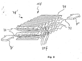
- FIG. 9 shows a perspective view of the particulate filter 7f 'which has been produced according to the inventive method described above. 9 corresponds to the particulate filter 7f 'shown in FIG. 9, but with the difference that a material of the particulate filter 7f' is a porous material permeable to the exhaust gas to be cleaned.
- the material band 31 is folded back and forth from the porous material permeable to the exhaust gas at the imaginary fold lines 32 extending transversely to the direction of extent of the material band 31.
- exhaust flow passages 21f are formed.
- these exhaust gas flow channels 21f are alternately closed at the exhaust gas inlet side (indicated by arrow P 'on the left image edge) and open at the exhaust gas outlet side (indicated by arrow P "on the right side of the image)
- the exhaust gas flowing into the particulate filter 7f 'in the direction of the arrow P' is forced to pass through the porous material band 31 as well as in the particulate filter shown in Figure 7.
- a material of the material strip 31 is coated with a catalyst material, so that the same applies to that already mentioned in FIG.
- an exhaust gas purifying assembly which comprises a plurality of plates each having a plurality of surface portions curved in opposite directions, the plurality of plates each having a plurality of contact surfaces against which adjacent plates abut each other, and adjacent flow plates defining exhaust gas flow channels and wherein for at least 50% of the contact surfaces of the two plates applies: D / A> 0.05, in particular> 0.07, more preferably> 0.10; where D is a maximum extent of the contact surfaces in the plane of the plate and A is a distance between the principal planes of the two plates.
- an exhaust gas purifier assembly comprising: providing a web of material; Forms of material band; Folding the material strip at fold lines; Laying the folded strip of material in sections to form a stack; and installing the stack in a housing.
Landscapes
- Chemical & Material Sciences (AREA)
- Chemical Kinetics & Catalysis (AREA)
- Engineering & Computer Science (AREA)
- Health & Medical Sciences (AREA)
- Toxicology (AREA)
- Combustion & Propulsion (AREA)
- Mechanical Engineering (AREA)
- General Engineering & Computer Science (AREA)
- Exhaust Gas After Treatment (AREA)
- Catalysts (AREA)
- Filtering Of Dispersed Particles In Gases (AREA)
Claims (34)
- Dispositif de purification des gaz d'échappement pour purifier les gaz d'échappement d'un moteur à combustion interne, comprenant :une pluralité de plaques (13), lesquelles présentent chacune en juxtaposition une multitude de zones superficielles, lesquelles sont courbées alternativement dans des directions opposées l'une à l'autre,la pluralité de plaques (13) étant assemblée pour former une pile (15), deux plaques (13, 13) contiguës dans la pile (15) présentant chacune une multiplicité de surfaces de contact (17, 17'), au niveau desquelles les deux plaques (13, 13) viennent en appui, et les deux plaques (13, 13) présentant un intervalle entre des zones d'appui voisines l'une de l'autre dans un plan de plaques, de sorte que des canaux d'écoulement de gaz d'échappement (21) sont délimités par les deux plaques (13, 13), et la règle étant pour au moins 50% des surfaces de contact (17, 17') des deux plaques (13, 13) :où

D est une étendue maximale des surfaces de contact (17, 17') dans le plan de plaques ; et
A est un intervalle entre des plans principaux des deux plaques (13, 13). - Dispositif de purification des gaz d'échappement selon la revendication 1, dans lequel au moins une des deux plaques contiguës (13, 13) présente une structure de plaque ondulée, de sorte que des sommets d'ondulation et des creux d'ondulation sont formés alternativement le long de lignes s'étendant essentiellement de façon rectiligne.
- Dispositif de purification des gaz d'échappement selon la revendication 2, dans lequel les surfaces de contact (17, 17') de la au moins une plaque (13) sont disposées, dans au moins une zone, à un intervalle par rapport au plan principal qui est plus faible qu'à l'extérieur de cette zone le long des lignes le long desquelles les sommets d'ondulation et les creux d'ondulation sont formés.
- Dispositif de purification des gaz d'échappement selon la revendication 2 ou 3, dans lequel les sommets d'ondulation et les creux d'ondulation des deux plaques (13, 13) à chaque fois contiguës dans la pile (15) sont orientées sous un angle de plus de 10° l'une par rapport à l'autre.
- Dispositif de purification des gaz d'échappement selon l'une quelconque des revendications 1 à 4, dans lequel des canaux d'écoulement de gaz d'échappement (21) qui sont ouverts côté entrée et fermés côté sortie sont disposés, dans le sens d'empilement, alternativement avec des canaux d'écoulement de gaz d'échappement (21) qui sont fermés côté entrée et ouverts côté sortie.
- Dispositif de purification des gaz d'échappement selon la revendication 5, dans lequel les plaques (13, 13) délimitant le canal d'écoulement des gaz (21) fermé côté sortie ou côté entrée se joignent entre elles, au niveau du côté sortie ou du côté entrée, le long d'une ligne perpendiculaire au sens d'écoulement.
- Dispositif de purification des gaz d'échappement selon la revendication 6, dans lequel les plaques (13, 13) délimitant le canal d'écoulement des gaz (21) fermé côté sortie ou côté entrée sont rattachées l'une à l'autre le long de la ligne par collage et/ou par soudage et/ou par sertissage.
- Dispositif de purification des gaz d'échappement selon la revendication 6, dans lequel les plaques (13, 13) délimitant le canal d'écoulement des gaz (21) fermé côté sortie ou côté entrée sont rattachées l'une à l'autre, au niveau du côté sortie ou du côté entrée, par une branche (29) continue s'étendant perpendiculairement au sens d'écoulement.
- Dispositif de purification des gaz d'échappement selon la revendication 6, dans lequel les plaques (13, 13) délimitant le canal d'écoulement des gaz fermé côté sortie ou côté entrée sont rattachées l'une à l'autre intégralement au niveau du côté sortie ou du côté entrée.
- Dispositif de purification des gaz d'échappement selon l'une quelconque des revendications 1 à 9, dans lequel un intervalle de plan principal entre deux plaques (13, 13) directement voisines présente une valeur située dans une plage de 0,5 mm à 8,0 mm, en particulier de 1,0 mm à 4,0 mm, et d'une manière également préférée de 1,5 mm à 3,0 mm.
- Dispositif de purification des gaz d'échappement selon l'une quelconque des revendications 2 à 10, dans lequel une déviation des sommets d'ondulation et des creux d'ondulation à chaque fois à partir des plans principaux est supérieure à 1 mm.
- Dispositif de purification des gaz d'échappement selon l'une quelconque des revendications 2 à 11, dans lequel une déviation des sommets d'ondulation et des creux d'ondulation à partir de leurs plans principaux est inférieure à 7 mm, en particulier inférieure à 5 mm et d'une manière également préférée inférieure à 3 mm.
- Dispositif de purification des gaz d'échappement selon l'une quelconque des revendications 2 à 12, dans lequel un intervalle latéral (longueur d'ondulation) dans le sens de développement de plaque entre des sommets d'ondulation ou des creux d'ondulation contigus est supérieur à 2 mm, en particulier supérieur à 3 mm.
- Dispositif de purification des gaz d'échappement selon l'une quelconque des revendications 2 à 13, dans lequel un intervalle latéral (longueur d'ondulation) dans le sens de développement de plaque entre des sommets d'ondulation ou des creux d'ondulation contigus est inférieur à 7 mm, en particulier inférieur à 5 mm.
- Dispositif de purification des gaz d'échappement selon l'une quelconque des revendications 1 à 14, dans lequel une épaisseur des plaques (13) est supérieure à 0,1 mm, en particulier supérieure à 0,3 mm.
- Dispositif de purification des gaz d'échappement selon l'une quelconque des revendications 1 à 15, dans lequel une épaisseur des plaques (13) est inférieure à 2,0 mm, en particulier inférieure à 1,2 mm.
- Dispositif de purification des gaz d'échappement selon l'une quelconque des revendications 1 à 16, dans lequel un matériau des plaques (13) est une tôle métallique.
- Dispositif de purification des gaz d'échappement selon l'une quelconque des revendications 1 à 16, dans lequel un matériau des plaques (13) est un matériau poreux perméable aux gaz d'échappement.
- Dispositif de purification des gaz d'échappement selon la revendication 18, dans lequel le matériau est un tissu et/ou un non-tissé et/ou un produit tressé réalisé à partir de fibres.
- Dispositif de purification des gaz d'échappement selon la revendication 19, dans lequel le matériau à base de fibres comprend des fibres métalliques et/ou des fibres céramiques.
- Dispositif de purification des gaz d'échappement selon l'une quelconque des revendications 1 à 20, dans lequel l'un des matériaux des plaques (13) est réalisé à base d'une poudre.
- Dispositif de purification des gaz d'échappement selon l'une quelconque des revendications 1 à 20, dans lequel l'un des matériaux des plaques est une mousse.
- Dispositif de purification des gaz d'échappement selon l'une quelconque des revendications 1 à 20, dans lequel un matériau des plaques (13) est réalisé sous forme de comprimé fritté.
- Dispositif de purification des gaz d'échappement selon l'une quelconque des revendications 1 à 23, dans lequel un matériau des plaques (13) contient un matériau catalyseur, en particulier en au moins un métal précieux et/ou au moins un oxyde métallique et/ou au moins un oxyde mixte, et/ou contient un matériau accumulateur d'oxygène, lequel contient en particulier du cérium et/ou un oxyde cérique et est revêtu en particulier par celui-ci.
- Dispositif de purification des gaz d'échappement selon l'une quelconque des revendications 1 à 24, dans lequel la pile (15) est délimitée, au niveau son côté extérieur, par au moins une nappe en matériau à base de fibres et/ou au moins une couche de non-tissé dans une zone entre le côté entrée et le côté sortie.
- Dispositif de purification des gaz d'échappement selon la revendication 25, dans lequel la au moins une nappe en matériau à base de fibres et/ou la au moins une couche de non-tissé entoure la pile (15) dans la zone entre le côté entrée et le côté sortie.
- Procédé de fabrication d'un dispositif de purification des gaz d'échappement pour purifier les gaz d'échappement d'un moteur à combustion interne, en particulier d'un dispositif de purification des gaz d'échappement selon l'une quelconque des revendications 1 à 26, le procédé comprenant :la mise à disposition d'une bande de matière (31) ;le formage de la bande de matière (31) à l'aide de cylindres de gaufrage (33, 35) pour former une bande de matière (31) ondulée, des sommets d'ondulation et des creux d'ondulation étant formés alternativement dans la bande de matière (31) le long de lignes s'étendant de façon sensiblement rectiligne, et les sommets d'ondulation et/ou les creux d'ondulation en sections dans le sens de développement de la bande de matière ondulée (31) étant conçus avec des zones de déformation, les zones de déformation étant disposées - dans au moins une section de bande de matière - au moins sectoriellement à un intervalle par rapport à un plan principal de la bande de matière ondulée (31) qui est plus faible que le long des lignes entre des zones de déformation voisines, de sorte qu'aprèsle pliage de la bande de matière (31) au niveau de lignes de pliage (32) s'étendant perpendiculairement à un sens de développement de la bande de matière (31), lesquelles lignes étant disposées à un certain intervalle les unes des autres dans le sens de développement de la bande de matière (31), et qu'aprèsla superposition des sections de bande de matière pliée (31) de telle façon qu'une pile (15f) est formée, deux sections de bande de matière contiguës dans la pile (15f) sont juxtaposées l'une contre l'autre au niveau des zones de déformation ; etle montage de la pile (15f) dans un carter.
- Procédé selon la revendication 27, dans lequel la bande de matière (31) est formée à partir d'un matériau poreux perméable aux gaz à purifier.
- Procédé selon la revendication 27 ou 28, dans lequel la bande de matière (31) passe, lors du pliage, entre deux cylindres de gaufrage (33, 35) pour réaliser des zones de déformation le long des lignes de pliage (32).
- Procédé selon la revendication 29, dans lequel les zones de déformation sont aménagées par enfoncement de la bande de matière (31) dans au moins un évidement longitudinal (39) prévu sur un premier des deux cylindres (35) par l'intermédiaire d'au moins un renflement longitudinal (37) prévu sur un deuxième des deux cylindres (33).
- Procédé selon la revendication 30, dans lequel le au moins un évidement longitudinal (39) s'étend parallèlement à un axe (35') du premier cylindre (35) et le au moins un renflement (37) s'étend parallèlement à un axe (33') du deuxième cylindre (33).
- Procédé selon l'une quelconque des revendications 29 à 31, dans lequel des renflements (37) et des évidements (39) adjacents sont prévus pour l'ondulation de la bande de matière (31) sur une surface (33", 35") des premier et deuxième cylindres (33, 35) dans le sens périphérique des cylindres (33, 35), lesquels renflements et évidements s'étendent en spirale autour des axes (33', 35') des cylindres (33, 35).
- Procédé selon la revendication 32, dans lequel un nombre pair de zones périphériques (43, 45) est à chaque fois prévu sur les premier et deuxième cylindres (33, 35), lesquelles zones sont chacune délimitées dans le sens périphérique par un renflement longitudinal (37) d'une part et par un évidement longitudinal (39) d'autre part, et dans lequel les orientations des renflements (37) et des évidements (39) en spirale sont opposées l'une à l'autre dans des zones périphériques voisines l'une de l'autre dans le sens périphérique.
- Procédé selon l'une quelconque des revendications 29 à 33, dans lequel une nappe en matériau à tricot métallique et/ou un voile métallique et/ou un matériau céramique et/ou un matériau céramique à base de fibres est inséré(e) entre le carter et la pile.
Applications Claiming Priority (2)
| Application Number | Priority Date | Filing Date | Title |
|---|---|---|---|
| DE102004004042 | 2004-01-27 | ||
| DE102004004042A DE102004004042B9 (de) | 2004-01-27 | 2004-01-27 | Abgasreinigungsanordnung und Verfahren zur Herstellung einer Abgasreinigungsanordnung |
Publications (2)
| Publication Number | Publication Date |
|---|---|
| EP1559882A1 EP1559882A1 (fr) | 2005-08-03 |
| EP1559882B1 true EP1559882B1 (fr) | 2007-09-19 |
Family
ID=34638755
Family Applications (1)
| Application Number | Title | Priority Date | Filing Date |
|---|---|---|---|
| EP05001368A Expired - Lifetime EP1559882B1 (fr) | 2004-01-27 | 2005-01-24 | Dispositif de purification des gaz d'échappement et procédé de fabrication d'un dispositif de purification des gaz d'échappement |
Country Status (2)
| Country | Link |
|---|---|
| EP (1) | EP1559882B1 (fr) |
| DE (2) | DE102004004042B9 (fr) |
Families Citing this family (5)
| Publication number | Priority date | Publication date | Assignee | Title |
|---|---|---|---|---|
| DE102010010024A1 (de) * | 2010-03-03 | 2011-09-08 | Alantum Europe Gmbh | Abgasreinigungsvorrichtung |
| EP2505800A1 (fr) * | 2011-03-30 | 2012-10-03 | Scambia Industrial Developments AG | Unité pour la réduction d'émission de polluants présents dans le gaz d'échappement d'un moteur à combustion interne |
| CN103670623B (zh) * | 2013-12-27 | 2016-08-17 | 吉林省众鑫汽车装备有限公司 | 汽车及金属纤维网载体 |
| KR101745169B1 (ko) * | 2015-11-04 | 2017-06-08 | 현대자동차주식회사 | 머플러 통합형 매연저감장치 |
| CN109942078B (zh) * | 2019-04-25 | 2024-05-28 | 深圳市绿洲生态科技有限公司 | 生物膜反应器水体净化装置和填料的制造方法 |
Family Cites Families (8)
| Publication number | Priority date | Publication date | Assignee | Title |
|---|---|---|---|---|
| JPS548202B2 (fr) * | 1972-12-07 | 1979-04-13 | ||
| DE3109609A1 (de) * | 1981-03-13 | 1982-09-23 | Kernforschungsanlage Jülich GmbH, 5170 Jülich | "schadstoff-filter fuer abgase" |
| DE3744265C2 (de) * | 1987-12-24 | 1996-07-11 | Emitec Emissionstechnologie | Rußfilter zur Abgasreinigung in Kraftfahrzeugen |
| US6207116B1 (en) * | 1994-08-04 | 2001-03-27 | Enklaven Ab | Catalytic purification device |
| JP3454018B2 (ja) * | 1996-06-06 | 2003-10-06 | 日産自動車株式会社 | メタル触媒担体の構造 |
| GB9621215D0 (en) * | 1996-10-11 | 1996-11-27 | Johnson Matthey Plc | Emission control |
| DE19702569A1 (de) * | 1997-01-24 | 1998-07-30 | Siemens Ag | Plattenkatalysator |
| WO2001028665A1 (fr) * | 1999-10-15 | 2001-04-26 | Abb Lummus Global, Inc. | Conversion d'oxydes d'azote en presence d'un catalyseur sur support a structure de type a mailles |
-
2004
- 2004-01-27 DE DE102004004042A patent/DE102004004042B9/de not_active Expired - Fee Related
-
2005
- 2005-01-24 DE DE502005001502T patent/DE502005001502D1/de not_active Expired - Lifetime
- 2005-01-24 EP EP05001368A patent/EP1559882B1/fr not_active Expired - Lifetime
Non-Patent Citations (1)
| Title |
|---|
| None * |
Also Published As
| Publication number | Publication date |
|---|---|
| EP1559882A1 (fr) | 2005-08-03 |
| DE102004004042B9 (de) | 2006-07-13 |
| DE102004004042A1 (de) | 2005-08-18 |
| DE102004004042B4 (de) | 2006-01-05 |
| DE502005001502D1 (de) | 2007-10-31 |
Similar Documents
| Publication | Publication Date | Title |
|---|---|---|
| EP1743697B1 (fr) | Bande métallique avec microstructure | |
| EP2027372B1 (fr) | Filtre à flux secondaire avec rendement de filtre amélioré | |
| DE20117873U1 (de) | Offener Filterkörper mit verbesserten Strömungseigenschaften | |
| DE19704147A1 (de) | Hitzebeständiger und regenerierbarer Filterkörper mit Strömungswegen | |
| EP1522686B1 (fr) | Dispositif de purification des gaz d'échappement | |
| EP1527262B1 (fr) | Filtre pour gaz d'echappement et procede d'epuration de gaz d'echappement | |
| EP2422060B1 (fr) | Procédé de fabrication d'un corps en nid d'abeilles revêtu et corps en nid d'abeilles correspondant | |
| EP1706608B1 (fr) | Corps en nid d'abeilles compose de couches comprenant des parties inversees et de couches comprenant des contre-structures | |
| EP1177370A1 (fr) | Moteur a combustion interne a pot catalytique de faible encombrement | |
| EP1853800B1 (fr) | Corps alveolaire a faces fissurees | |
| EP1834068B1 (fr) | Procede d'elimination de particules contenues dans des gaz d'echappement, couche fibreuse et filtre de particules appropries | |
| EP0470365B1 (fr) | Filtre | |
| EP1559882B1 (fr) | Dispositif de purification des gaz d'échappement et procédé de fabrication d'un dispositif de purification des gaz d'échappement | |
| DE10356997A1 (de) | Partikelfilter | |
| EP1902203B1 (fr) | Couche filtrante pour un element alveolaire, notamment conique, de traitement de gaz d'echappement et procede pour fabriquer cette couche filtrante | |
| EP1789189B1 (fr) | Feuille metallique presentant des rainures differentes | |
| EP1431528B1 (fr) | Dispositif de purification des gaz d'échappement | |
| DE102004054845A1 (de) | Beschichtete Partikelfalle mit Stickstoffdioxid-Neubildung | |
| DE10301138A1 (de) | Platzsparende Abgasnachbehandlungseinheit mit ineinanderliegenden Hin- und Rückströmbereichen bei gleichseitigem Gasein- und -austritt | |
| EP1787705A1 (fr) | Dispositif filtrant, en particulier, pour un système de traitement des gaz d'échappement d'un moteur à combustion interne du type Diesel | |
| DE102010010024A1 (de) | Abgasreinigungsvorrichtung | |
| DE202010017505U1 (de) | Abgasreinigungsvorrichtung |
Legal Events
| Date | Code | Title | Description |
|---|---|---|---|
| PUAI | Public reference made under article 153(3) epc to a published international application that has entered the european phase |
Free format text: ORIGINAL CODE: 0009012 |
|
| AK | Designated contracting states |
Kind code of ref document: A1 Designated state(s): AT BE BG CH CY CZ DE DK EE ES FI FR GB GR HU IE IS IT LI LT LU MC NL PL PT RO SE SI SK TR |
|
| AX | Request for extension of the european patent |
Extension state: AL BA HR LV MK YU |
|
| 17P | Request for examination filed |
Effective date: 20060203 |
|
| AKX | Designation fees paid |
Designated state(s): DE FR GB IT SE |
|
| 17Q | First examination report despatched |
Effective date: 20060309 |
|
| GRAP | Despatch of communication of intention to grant a patent |
Free format text: ORIGINAL CODE: EPIDOSNIGR1 |
|
| GRAS | Grant fee paid |
Free format text: ORIGINAL CODE: EPIDOSNIGR3 |
|
| GRAA | (expected) grant |
Free format text: ORIGINAL CODE: 0009210 |
|
| AK | Designated contracting states |
Kind code of ref document: B1 Designated state(s): DE FR GB IT SE |
|
| REG | Reference to a national code |
Ref country code: GB Ref legal event code: FG4D Free format text: NOT ENGLISH |
|
| REF | Corresponds to: |
Ref document number: 502005001502 Country of ref document: DE Date of ref document: 20071031 Kind code of ref document: P |
|
| GBT | Gb: translation of ep patent filed (gb section 77(6)(a)/1977) |
Effective date: 20071029 |
|
| REG | Reference to a national code |
Ref country code: SE Ref legal event code: TRGR |
|
| ET | Fr: translation filed | ||
| PLBE | No opposition filed within time limit |
Free format text: ORIGINAL CODE: 0009261 |
|
| STAA | Information on the status of an ep patent application or granted ep patent |
Free format text: STATUS: NO OPPOSITION FILED WITHIN TIME LIMIT |
|
| 26N | No opposition filed |
Effective date: 20080620 |
|
| PGFP | Annual fee paid to national office [announced via postgrant information from national office to epo] |
Ref country code: IT Payment date: 20090126 Year of fee payment: 5 |
|
| PG25 | Lapsed in a contracting state [announced via postgrant information from national office to epo] |
Ref country code: IT Free format text: LAPSE BECAUSE OF NON-PAYMENT OF DUE FEES Effective date: 20100124 |
|
| PGFP | Annual fee paid to national office [announced via postgrant information from national office to epo] |
Ref country code: SE Payment date: 20110629 Year of fee payment: 7 |
|
| PGFP | Annual fee paid to national office [announced via postgrant information from national office to epo] |
Ref country code: GB Payment date: 20110629 Year of fee payment: 7 |
|
| PGFP | Annual fee paid to national office [announced via postgrant information from national office to epo] |
Ref country code: FR Payment date: 20110801 Year of fee payment: 7 |
|
| REG | Reference to a national code |
Ref country code: SE Ref legal event code: EUG |
|
| GBPC | Gb: european patent ceased through non-payment of renewal fee |
Effective date: 20120124 |
|
| REG | Reference to a national code |
Ref country code: FR Ref legal event code: ST Effective date: 20120928 |
|
| PG25 | Lapsed in a contracting state [announced via postgrant information from national office to epo] |
Ref country code: GB Free format text: LAPSE BECAUSE OF NON-PAYMENT OF DUE FEES Effective date: 20120124 Ref country code: SE Free format text: LAPSE BECAUSE OF NON-PAYMENT OF DUE FEES Effective date: 20120125 |
|
| PG25 | Lapsed in a contracting state [announced via postgrant information from national office to epo] |
Ref country code: FR Free format text: LAPSE BECAUSE OF NON-PAYMENT OF DUE FEES Effective date: 20120131 |
|
| PGFP | Annual fee paid to national office [announced via postgrant information from national office to epo] |
Ref country code: DE Payment date: 20131230 Year of fee payment: 10 |
|
| REG | Reference to a national code |
Ref country code: DE Ref legal event code: R119 Ref document number: 502005001502 Country of ref document: DE |
|
| PG25 | Lapsed in a contracting state [announced via postgrant information from national office to epo] |
Ref country code: DE Free format text: LAPSE BECAUSE OF NON-PAYMENT OF DUE FEES Effective date: 20150801 |