EP1559897A2 - Appareil de commande de l'injection de carburant pour un moteur à allumage commandé avec injection directe - Google Patents
Appareil de commande de l'injection de carburant pour un moteur à allumage commandé avec injection directe Download PDFInfo
- Publication number
- EP1559897A2 EP1559897A2 EP05001426A EP05001426A EP1559897A2 EP 1559897 A2 EP1559897 A2 EP 1559897A2 EP 05001426 A EP05001426 A EP 05001426A EP 05001426 A EP05001426 A EP 05001426A EP 1559897 A2 EP1559897 A2 EP 1559897A2
- Authority
- EP
- European Patent Office
- Prior art keywords
- fuel injection
- fuel
- injection
- timing
- control section
- Prior art date
- Legal status (The legal status is an assumption and is not a legal conclusion. Google has not performed a legal analysis and makes no representation as to the accuracy of the status listed.)
- Withdrawn
Links
- 238000002347 injection Methods 0.000 title claims abstract description 156
- 239000007924 injection Substances 0.000 title claims abstract description 156
- 239000000446 fuel Substances 0.000 title claims abstract description 151
- 238000002485 combustion reaction Methods 0.000 claims abstract description 53
- 230000006835 compression Effects 0.000 claims abstract description 52
- 238000007906 compression Methods 0.000 claims abstract description 52
- 238000000034 method Methods 0.000 claims 1
- 239000003054 catalyst Substances 0.000 abstract description 29
- 238000010792 warming Methods 0.000 abstract description 10
- 230000004913 activation Effects 0.000 abstract description 6
- 239000007921 spray Substances 0.000 abstract description 4
- 230000006870 function Effects 0.000 description 9
- 239000002826 coolant Substances 0.000 description 7
- 230000003197 catalytic effect Effects 0.000 description 6
- 239000000203 mixture Substances 0.000 description 6
- 230000000694 effects Effects 0.000 description 2
- 239000007789 gas Substances 0.000 description 2
- 230000001737 promoting effect Effects 0.000 description 2
- 238000000746 purification Methods 0.000 description 2
- QVGXLLKOCUKJST-UHFFFAOYSA-N atomic oxygen Chemical compound [O] QVGXLLKOCUKJST-UHFFFAOYSA-N 0.000 description 1
- 230000000052 comparative effect Effects 0.000 description 1
- 230000003111 delayed effect Effects 0.000 description 1
- 238000001514 detection method Methods 0.000 description 1
- 230000006872 improvement Effects 0.000 description 1
- 238000012986 modification Methods 0.000 description 1
- 230000004048 modification Effects 0.000 description 1
- 239000001301 oxygen Substances 0.000 description 1
- 229910052760 oxygen Inorganic materials 0.000 description 1
- 230000002093 peripheral effect Effects 0.000 description 1
- 230000000717 retained effect Effects 0.000 description 1
- 230000007704 transition Effects 0.000 description 1
- XLYOFNOQVPJJNP-UHFFFAOYSA-N water Substances O XLYOFNOQVPJJNP-UHFFFAOYSA-N 0.000 description 1
Images


Classifications
-
- F—MECHANICAL ENGINEERING; LIGHTING; HEATING; WEAPONS; BLASTING
- F02—COMBUSTION ENGINES; HOT-GAS OR COMBUSTION-PRODUCT ENGINE PLANTS
- F02D—CONTROLLING COMBUSTION ENGINES
- F02D37/00—Non-electrical conjoint control of two or more functions of engines, not otherwise provided for
- F02D37/02—Non-electrical conjoint control of two or more functions of engines, not otherwise provided for one of the functions being ignition
-
- F—MECHANICAL ENGINEERING; LIGHTING; HEATING; WEAPONS; BLASTING
- F02—COMBUSTION ENGINES; HOT-GAS OR COMBUSTION-PRODUCT ENGINE PLANTS
- F02D—CONTROLLING COMBUSTION ENGINES
- F02D41/00—Electrical control of supply of combustible mixture or its constituents
- F02D41/30—Controlling fuel injection
- F02D41/38—Controlling fuel injection of the high pressure type
- F02D41/40—Controlling fuel injection of the high pressure type with means for controlling injection timing or duration
- F02D41/402—Multiple injections
- F02D41/405—Multiple injections with post injections
-
- F—MECHANICAL ENGINEERING; LIGHTING; HEATING; WEAPONS; BLASTING
- F02—COMBUSTION ENGINES; HOT-GAS OR COMBUSTION-PRODUCT ENGINE PLANTS
- F02D—CONTROLLING COMBUSTION ENGINES
- F02D41/00—Electrical control of supply of combustible mixture or its constituents
- F02D41/30—Controlling fuel injection
- F02D41/38—Controlling fuel injection of the high pressure type
- F02D2041/389—Controlling fuel injection of the high pressure type for injecting directly into the cylinder
-
- F—MECHANICAL ENGINEERING; LIGHTING; HEATING; WEAPONS; BLASTING
- F02—COMBUSTION ENGINES; HOT-GAS OR COMBUSTION-PRODUCT ENGINE PLANTS
- F02D—CONTROLLING COMBUSTION ENGINES
- F02D41/00—Electrical control of supply of combustible mixture or its constituents
- F02D41/30—Controlling fuel injection
- F02D41/38—Controlling fuel injection of the high pressure type
- F02D41/40—Controlling fuel injection of the high pressure type with means for controlling injection timing or duration
- F02D41/401—Controlling injection timing
-
- F—MECHANICAL ENGINEERING; LIGHTING; HEATING; WEAPONS; BLASTING
- F02—COMBUSTION ENGINES; HOT-GAS OR COMBUSTION-PRODUCT ENGINE PLANTS
- F02D—CONTROLLING COMBUSTION ENGINES
- F02D41/00—Electrical control of supply of combustible mixture or its constituents
- F02D41/30—Controlling fuel injection
- F02D41/38—Controlling fuel injection of the high pressure type
- F02D41/40—Controlling fuel injection of the high pressure type with means for controlling injection timing or duration
- F02D41/402—Multiple injections
- F02D41/403—Multiple injections with pilot injections
-
- Y—GENERAL TAGGING OF NEW TECHNOLOGICAL DEVELOPMENTS; GENERAL TAGGING OF CROSS-SECTIONAL TECHNOLOGIES SPANNING OVER SEVERAL SECTIONS OF THE IPC; TECHNICAL SUBJECTS COVERED BY FORMER USPC CROSS-REFERENCE ART COLLECTIONS [XRACs] AND DIGESTS
- Y02—TECHNOLOGIES OR APPLICATIONS FOR MITIGATION OR ADAPTATION AGAINST CLIMATE CHANGE
- Y02T—CLIMATE CHANGE MITIGATION TECHNOLOGIES RELATED TO TRANSPORTATION
- Y02T10/00—Road transport of goods or passengers
- Y02T10/10—Internal combustion engine [ICE] based vehicles
- Y02T10/40—Engine management systems
Definitions
- the present invention generally relates to a control device for a direct fuel injection spark ignition engine. More specifically, the present invention relates to a control device that is suitable during cold starting and the other times, or when it is necessary to warm up a catalyst for exhaust purification provided to the exhaust channel.
- Japanese Patent No. 3325230 discloses a fuel injection control that is applied when the catalytic converter is in an un-warmed state, i.e., when the temperature of the catalyst is lower than its activation temperature.
- the fuel injection is divided into at least two injection composed of an early-stage injection and a later-stage injection.
- an air-fuel mixture with a partially variable air-fuel ratio is formed in an interval that extends from the intake stroke to ignition timing.
- fuel is injected prior to the later-stage injection such that an air-fuel mixture with an air-fuel ratio that is leaner than the theoretical air fuel ratio is generated to allow combustion to be extended using the fuel of the later-stage injection.
- the ignition timing is retarded by a predetermined amount from MBT.
- the ignition timing in the no-load region of the engine is set to occur prior to the compression top dead center; and ignition timing in the low-speed, low-load region, excluding the no-load region, of the engine is retarded until the compression top dead center or later.
- ignition timing delay is effective for promoting afterburning in order to reduce HC and achieve early catalyst warming when the engine is cold.
- Ignition preferably occurs at compression top dead center or later to achieve an even greater effect, but the combustion interval must be shortened in order to carry out stable combustion with ATDC ignition. For this reason, the turbulence in the cylinder must be enhanced and combustion velocity (flame propagation velocity) increased.
- combustion velocity flame propagation velocity
- the first fuel injection (early-stage injection) is principally carried out in the intake stroke and the second fuel injection (later-stage injection) is carried out at 120 to 45° BTDC in the compression stroke, and even if turbulence is generated in the cylinder by the spray from the first fuel injection in the intake stroke, the turbulence weakens in the compression stroke and does not contribute to an increase in the flame propagation velocity at ATDC ignition.
- the contribution of the second fuel injection to improved combustion is small in the sense that even if turbulence is generated in the cylinder by the spray prior to 45° BTDC, the turbulence is lessened by the time ATDC ignition occurs.
- ATDC is more effective in reducing HC and increasing the exhaust temperature, but since combustion is not stabilized, BTDC ignition is used in the no-load range in Japanese Patent No. 3325230.
- an object of the present invention is to improve the combustion stability in ATDC ignition in order to reduce HC during cold starting and the other times and/or to activate the catalyst at an early stage.
- a direct fuel injection/spark ignition engine control device that basically comprises a fuel injection control section and an ignition timing control section.
- the fuel injection control section is configured to control fuel injections of a fuel injection valve that directly injects fuel into a combustion chamber.
- the ignition timing control section is configured to control sparking of a spark plug disposed in the combustion chamber such that an ignition timing is set to ignite fuel at or after a compression top dead center.
- the fuel injection control section is further configured to set a compression stroke fuel injection timing.
- the fuel injection control section is further configured to set a first fuel injection with a first injection start timing and a first injection end timing that both occur in a compression stroke.
- the fuel injection control section is further configured to set a second fuel injection having a second injection start timing and a second injection end timing that both occur in a second half of the compression stroke before the compression top dead center.
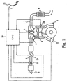
- Figure 1 is a diagrammatic view of an engine system illustrating a direct fuel injection/spark ignition engine control device for an internal combustion engine in accordance with the present invention
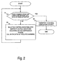
- FIG. 2 is a flowchart showing the control operations executed from startup to during warm-up by the control unit of the direct fuel injection/spark ignition engine control device in accordance with the present invention
- Figure 3 is a graph showing the turbulence in the cylinder when a gas flow control valve housed in the intake port is used.
- Figure 4 is a fuel injection timing chart showing the fuel injections in accordance with a first embodiment of the present invention.
- a direct fuel injection/spark ignition internal combustion engine 1 is diagrammatically illustrated that is equipped with a direct fuel injection/spark ignition engine control device in accordance with a first embodiment of the present invention.
- the engine 1 has an intake passage 2 with an electronically controlled throttle valve 3 mounted therein.
- the electronically controlled throttle valve 3 is configured and arranged for controlling the intake air quantity to the intake passage 2 of the engine 1.
- the intake passage 2 is fluidly connected to a plurality of combustion chambers 4 (only one shown) of the engine 1.
- Each combustion chamber 4 includes a spark plug 5 and a fuel injection valve 6.
- the spark plug 5 and the fuel injection valve 6 are mounted to the combustion chamber 4 in a conventional manner.
- the engine 1 also has an exhaust passage 7 fluidly connected to each combustion chamber 4.
- the exhaust passage 7 includes a catalytic converter 8 with a catalyst for exhaust purification in a conventional manner.
- the engine is controlled by an engine control unit or ECU 20 to perform the controlled combustion of the fuel air mixture as discussed below.
- the engine control unit 20 forms a direct fuel injection/spark ignition engine control device that includes a fuel injection control section and an ignition timing control section (see steps S2 and S3 of Figure 2).
- the ignition timing is set to compression top dead center or later when needed such as when the catalyst requires warming.
- a compression stroke fuel injection timing is divided into a first fuel injection that is carried out during the compression stroke and a second fuel injection that is carried out at 45° prior to compression top dead center or later.
- the engine control unit 20 is a microcomputer comprising of a central processing unit (CPU) and other peripheral devices.
- the engine control unit 20 can also include other conventional components such as an input interface circuit, an output interface circuit, and storage devices such as a ROM (Read Only Memory) device and a RAM (Random Access Memory) device.
- the engine control unit 20 preferably includes an engine control program that controls various components as discussed below.
- the engine control unit 20 receives input signals from various sensors (described below) that serve to detect the operating state of the engine 1 and executes the engine controls based on these signals. It will be apparent to those skilled in the art from this disclosure that the precise structure and algorithms for the engine control unit 20 can be any combination of hardware and software that will carry out the functions of the present invention.
- "means plus function" clauses as utilized in the specification and claims should include any structure or hardware and/or algorithm or software that can be utilized to carry out the function of the "means plus function” clause.
- the opening of the electronically controlled throttle valve 3 is controlled by a stepping motor or other device operated by the signal from the engine control unit 20.
- the electrically controlled throttle valve 3 controls the intake air quantity or amount to the combustion chambers 4 of the engine 1 via the intake passage 2.
- Each of the fuel injection valves 6 is configured so as to be opened by a solenoid energized by an injection pulse signal outputted from the engine control unit 20 in synchronization with the engine speed during an intake stroke or a compression stroke.
- Each of the fuel injection valves 6 injects fuel that is pressurized at a prescribed pressure.
- the fuel injected is distributed throughout the combustion chamber 4 such that a homogenous air/fuel mixture is formed in the case of an intake stroke injection, and a stratified air/fuel mixture is formed around the spark plug 5 in the case of a compression stroke injection.
- the air/fuel mixture is ignited by the spark plug 5 based on an ignition signal from the engine control unit 20, and is burned (homogenous combustion mode, stratified combustion mode).
- the engine control unit 20 receives input signals from the following sensors: an accelerator pedal sensor 21, a crank angle sensor 22, a hot-wire airflow meter 23, a throttle sensor 24, and an engine coolant temperature sensor 25.
- the engine control unit 20 executes the engine controls including, but not limited to, the intake air quantity Qa, the ignition timing, the fuel injection quantity and fuel injection timing based on these signals.
- the accelerator opening APO is detected by the accelerator pedal sensor 21, which outputs a signal to the engine control unit 20 that is indicative of the depression amount of the accelerator pedal.
- the engine speed Ne is detected by the crank angle sensor 22, which outputs a signal to the engine control unit 20 that is indicative of the engine speed Ne.
- the intake air quantity Qa is detected by the airflow meter 23, which outputs a signal to the engine control unit 20 that is indicative of the intake air quantity Qa.
- the throttle position TVO is detected by the throttle sensor 24, which outputs a signal to the engine control unit 20 that is indicative of the throttle position TVO.
- the engine coolant temperature or water temperature Tw is detected by the engine coolant temperature sensor 25, which outputs a signal to the engine control unit 20 that is indicative of the engine coolant temperature Tw.
- the present invention entails performing optimum combustion control according to load conditions when warming up is required for the catalyst in the catalytic converter 8, which includes cold starting. This type of control is performed by the engine control unit 20 as control from startup through warm-up of the catalyst in accordance with the flowchart in Figure 2.
- step S1 a determination is made whether the catalyst of the catalytic converter 8 has been activated. Specifically, when a catalyst temperature sensor is provided, the catalyst temperature is detected thereby. When a catalyst temperature sensor is not provided, the catalyst temperature is estimated from the coolant temperature Tw that is detected by the engine coolant temperature sensor 25. The catalyst temperature can alternatively be estimated based on the coolant temperature at startup and the integrated value of the intake amount after startup. In any case, a determination is made whether the detected or estimated catalyst temperature is equal to or greater than the predetermined activation temperature. When the catalyst of the catalytic converter 8 has not been activated, the system advances to step S2.
- step S2 the ignition timing is delayed until compression top dead center (TDC) or later as the type of control performed when the catalyst requires warming.
- TDC compression top dead center
- the ignition timing is set to between TDC and 15° ATDC to perform ATDC ignition.
- the fuel injection is preferably divided into two fuel injections that are carried out between the start of the compression stroke and prior to ignition. More preferably, the fuel injections that are carried out such that both the injection start timing and the injection end timing occur in the compression stroke.
- step S1 After the catalyst of the catalytic converter 8 has been activated by control when the catalyst requires warming, the system advances from step S1 to step S3 and transitions to normal control.
- normal control In normal control, the above-described stratified lean combustion, homogenous lean combustion, stoichiometric combustion, and other types of combustion are carried out in accordance with the operating conditions.
- Ignition timing delay is effective for reducing HC and promoting catalyst warming when the engine 1 is cold, and ignition (ATDC ignition) preferably occurs at TDC or later.
- ignition ATDC ignition
- the combustion time is reduced in order to achieve stable combustion with ATDC ignition, and flame propagation produced by turbulence is therefore promoted.
- the turbulence at ignition timing or later is increased in order to promote flame propagation, and a gas flow control valve (tumble control valve, for example) disposed in the intake port can be operated, for example.
- a gas flow control valve tumble control valve, for example
- the turbulence (point A) generated in the intake stroke weakens as the compression stroke progresses.
- point B the tumble flow produced by the piston in the second half of the compression stroke
- point C little improvement (improved flame propagation) in the combustion can be expected to be achieved using this turbulence. For this reason, it is possible to consider using turbulence produced by high-pressure fuel injection.
- the first fuel injection is carried out during the compression stroke and the second fuel injection is carried out at 45° BTDC or later (preferably 20° BTDC or later).
- the first fuel injection contributes to a stable ATDC ignition when carried out in the compression stroke and when the time until ignition is short (time from the generation of turbulence to the dissipation thereof).
- the turbulence generated by the first fuel injection can be improved or enhance by performing the second fuel injection at 45° BTDC or later (preferably 20° BTDC, or later) after the first fuel injection has been performed. This promotes the flame propagation at ATDC ignition.
- the first fuel injection is carried out in the first half of the compression stroke.
- greater turbulence can be obtained by carrying out the first fuel injection in the second half of the compression stroke since the turbulence begins to dissipate when the first fuel injection is carried out in the first half of the compression stroke.
- fuel injection is divided into two fuel injections in Examples 2 and 3 of Figure 4, with both of the fuel injections being performed in the second half of the compression stroke (90° BTDC or later).
- the first fuel injection is carried out at 90° BTDC to 45° BTDC and the second fuel injection is carried out at 45° BTDC or later (more preferable timing it 20° BTDC or later).
- the first fuel injection is carried out at 45° BTDC or later and the second fuel injection is carried out at 20° BTDC or later in order to carry out both fuel injections at 45° BTDC or later so that the turbulence can be further enhanced.
- combustion stability can be improved (promotion of flame propagation) when carrying out ATDC ignition to reduce HC and/or achieve early activation of the catalyst by setting the ignition timing to ATDC.
- the turbulence in the combustion chamber 4 can be further enhanced and combustion stability improved by carrying out both fuel injections in this case at 20° prior to compression top dead center or later.
- turbulence is generated by the first fuel injection in the compression stroke, and the turbulence is enhanced by the second fuel injection in extremely close proximity with ignition timing and stably retained until ignition timing or later by setting the ignition timing to ATDC when the catalyst requires warming, and dividing fuel injection into two fuel injections in which the first fuel injection is carried out during the compression stroke and the second fuel injection straddles the compression TDC or is carried out in the expansion stroke prior to ignition timing.
- Combustion stability can therefore be improved (flame propagation promoted) when carrying out ATDC ignition to reduce HC and/or achieve early activation of the catalyst.
- turbulence is generated by the first fuel injection in the compresion stroke, and the turbulence is additionally enhanced by the second fuel injection.
- combustion stability can be improved (promote flame propagation) when carrying out ATDC ignition to reduce HC and/or achieve early activation of the catalyst.
- the turbulence in the combustion chamber 4 can be enhanced and combustion stability improved by carrying out both fuel injections in this case at 45° BTDC or later, and furthermore carrying out the first fuel injection at 45° BTDC or later and the second fuel injection at 20° BTDC or later.
- the following directional terms "forward, rearward, above, downward, vertical, horizontal, below and transverse” as well as any other similar directional terms refer to those directions of a vehicle equipped with the present invention. Accordingly, these terms, as utilized to describe the present invention should be interpreted relative to a vehicle equipped with the present invention.
- the term "detect” as used herein to describe an operation or function carried out by a component, a section, a device or the like includes a component, a section, a device or the like that does not require physical detection, but rather includes determining or computing or the like to carry out the operation or function.
Landscapes
- Engineering & Computer Science (AREA)
- Chemical & Material Sciences (AREA)
- Combustion & Propulsion (AREA)
- Mechanical Engineering (AREA)
- General Engineering & Computer Science (AREA)
- Electrical Control Of Air Or Fuel Supplied To Internal-Combustion Engine (AREA)
- Electrical Control Of Ignition Timing (AREA)
- Combustion Methods Of Internal-Combustion Engines (AREA)
- Exhaust Gas After Treatment (AREA)
- Combined Controls Of Internal Combustion Engines (AREA)
Applications Claiming Priority (2)
| Application Number | Priority Date | Filing Date | Title |
|---|---|---|---|
| JP2004020085 | 2004-01-28 | ||
| JP2004020085A JP2005214041A (ja) | 2004-01-28 | 2004-01-28 | 直噴火花点火式内燃機関の制御装置 |
Publications (2)
| Publication Number | Publication Date |
|---|---|
| EP1559897A2 true EP1559897A2 (fr) | 2005-08-03 |
| EP1559897A3 EP1559897A3 (fr) | 2006-01-04 |
Family
ID=34650795
Family Applications (1)
| Application Number | Title | Priority Date | Filing Date |
|---|---|---|---|
| EP05001426A Withdrawn EP1559897A3 (fr) | 2004-01-28 | 2005-01-25 | Appareil de commande de l'injection de carburant pour un moteur à allumage commandé avec injection directe |
Country Status (4)
| Country | Link |
|---|---|
| US (1) | US7051701B2 (fr) |
| EP (1) | EP1559897A3 (fr) |
| JP (1) | JP2005214041A (fr) |
| CN (1) | CN100378316C (fr) |
Families Citing this family (35)
| Publication number | Priority date | Publication date | Assignee | Title |
|---|---|---|---|---|
| DE102004017989B4 (de) * | 2004-04-14 | 2019-03-28 | Daimler Ag | Verfahren zum Betrieb einer Brennkraftmaschine mit Kraftstoffdirekteinspritzung |
| EP1643107B1 (fr) * | 2004-09-30 | 2010-10-27 | Nissan Motor Co., Ltd. | Procédé et dispositif de commande de combustion pour un moteur à injection directe et allumage commandé |
| EP1703112B1 (fr) * | 2005-02-22 | 2010-07-21 | Ford Global Technologies, LLC | Procédé de chauffage d'un catalyseur d'un moteur à combustion interne |
| JP4379919B2 (ja) * | 2005-03-14 | 2009-12-09 | セイコーエプソン株式会社 | 表示装置の製造方法および電子機器 |
| US7296555B2 (en) * | 2005-08-25 | 2007-11-20 | General Electric Company | System and method for operating a turbo-charged engine |
| DE102005048349A1 (de) * | 2005-10-10 | 2007-04-12 | Robert Bosch Gmbh | Verfahren zum Betrieb einer Brennkraftmaschine |
| CN100543287C (zh) * | 2005-11-30 | 2009-09-23 | 丰田自动车株式会社 | 缸内喷射式火花点火内燃机 |
| US7353786B2 (en) * | 2006-01-07 | 2008-04-08 | Scuderi Group, Llc | Split-cycle air hybrid engine |
| JP4905200B2 (ja) * | 2006-03-31 | 2012-03-28 | マツダ株式会社 | 火花点火式ガソリンエンジン |
| JP4793301B2 (ja) * | 2006-03-31 | 2011-10-12 | マツダ株式会社 | 火花点火式ガソリンエンジン |
| JP4905175B2 (ja) * | 2006-03-31 | 2012-03-28 | マツダ株式会社 | 火花点火式ガソリンエンジン |
| JP4793295B2 (ja) * | 2006-03-31 | 2011-10-12 | マツダ株式会社 | 火花点火式ガソリンエンジン |
| JP2007309264A (ja) * | 2006-05-19 | 2007-11-29 | Toyota Motor Corp | 車両の制御装置 |
| US7373928B2 (en) * | 2006-05-31 | 2008-05-20 | Joseph Thomas | Method for starting a direct injection engine |
| JP4850744B2 (ja) * | 2007-02-13 | 2012-01-11 | 日立オートモティブシステムズ株式会社 | 内燃機関の吸気制御装置 |
| US7767944B2 (en) * | 2007-03-07 | 2010-08-03 | Raytheon Company | Piezoelectric fiber, active damped, composite electronic housings |
| US8347860B2 (en) * | 2008-02-15 | 2013-01-08 | GM Global Technology Operations LLC | Control strategy for a homogeneous-charge compression-ignition engine |
| JP4479822B2 (ja) * | 2008-04-21 | 2010-06-09 | トヨタ自動車株式会社 | 筒内噴射式火花点火内燃機関 |
| US8165788B2 (en) | 2009-05-22 | 2012-04-24 | Ford Global Technlogies, Llc | Fuel-based injection control |
| US8272207B2 (en) * | 2009-07-31 | 2012-09-25 | Ford Global Technologies, Llc | Late post injection of fuel for particulate filter heating |
| CA2702246C (fr) * | 2010-04-20 | 2012-01-17 | Westport Power Inc. | Methode permettant la commande d'un systeme de moteur a combustion interne a carburant gazeux et a injection directe avec convertisseur a reduction catalytique selective |
| US8447496B2 (en) * | 2010-09-17 | 2013-05-21 | Ford Global Technologies, Llc | Fuel-based injection control |
| JP5572107B2 (ja) * | 2011-01-31 | 2014-08-13 | 本田技研工業株式会社 | 内燃機関の燃料噴射制御装置 |
| US8794212B2 (en) * | 2011-07-29 | 2014-08-05 | General Electric Company | Engine and method of operating engine |
| CN105143649B (zh) | 2013-03-11 | 2019-03-08 | 韦恩州立大学 | 内燃机中的预测校正 |
| US11078860B2 (en) | 2013-03-11 | 2021-08-03 | Wayne State University | Predictive correction in internal combustion engines |
| US9581126B2 (en) * | 2013-12-17 | 2017-02-28 | Ford Global Technologies, Llc | Engine control for limiting catalyst temperature in normal and economy modes |
| CN105020073B (zh) * | 2014-04-29 | 2018-01-16 | 长城汽车股份有限公司 | 用于双燃料发动机的喷油方法、装置和汽车 |
| JP6323683B2 (ja) * | 2015-06-03 | 2018-05-16 | マツダ株式会社 | エンジンの制御装置 |
| JP6323684B2 (ja) * | 2015-06-03 | 2018-05-16 | マツダ株式会社 | エンジンの制御装置 |
| JP6237734B2 (ja) * | 2015-09-02 | 2017-11-29 | トヨタ自動車株式会社 | 内燃機関の制御装置 |
| JP6763805B2 (ja) | 2016-07-05 | 2020-09-30 | トヨタ自動車株式会社 | 内燃機関の制御装置 |
| JP6658663B2 (ja) * | 2017-04-25 | 2020-03-04 | トヨタ自動車株式会社 | 内燃機関の制御装置 |
| US10781768B2 (en) | 2017-06-15 | 2020-09-22 | Nissan Motor Co., Ltd. | Control device for direct fuel injection engine and control method thereof |
| US11391230B2 (en) * | 2019-11-07 | 2022-07-19 | Saudi Arabian Oil Company | Compression ignition engines and methods for operating the same under cold start fast idle conditions |
Family Cites Families (20)
| Publication number | Priority date | Publication date | Assignee | Title |
|---|---|---|---|---|
| JPH03164549A (ja) * | 1989-11-22 | 1991-07-16 | Fuji Heavy Ind Ltd | 2サイクルエンジンのエンジン制御装置 |
| DE69421517T2 (de) | 1993-01-25 | 2000-04-27 | Orbital Engine Co. (Australia) Pty. Ltd., Balcatta | Verfahren zum betrieb einer brennkraftmaschine |
| JPH11294220A (ja) * | 1998-04-13 | 1999-10-26 | Mitsubishi Electric Corp | 筒内噴射式内燃機関の燃料噴射制御装置 |
| JP3325230B2 (ja) | 1998-08-03 | 2002-09-17 | マツダ株式会社 | 筒内噴射式エンジンの触媒暖機方法及び同装置 |
| JP3325231B2 (ja) * | 1998-08-03 | 2002-09-17 | マツダ株式会社 | 筒内噴射式エンジンの制御装置 |
| JP3613018B2 (ja) * | 1998-08-06 | 2005-01-26 | マツダ株式会社 | 筒内噴射式エンジンの制御装置 |
| JP2000120471A (ja) * | 1998-08-10 | 2000-04-25 | Mazda Motor Corp | 筒内噴射式エンジンの制御装置 |
| JP3767211B2 (ja) * | 1998-11-12 | 2006-04-19 | マツダ株式会社 | 筒内噴射式エンジンの制御装置 |
| JP3671785B2 (ja) | 1999-12-15 | 2005-07-13 | 株式会社日立製作所 | 筒内噴射型内燃機関の燃料噴射装置 |
| US6401688B2 (en) * | 2000-01-27 | 2002-06-11 | Nissan Motor Co., Ltd. | Auto-ignition combustion management in internal combustion engine |
| JP3760725B2 (ja) * | 2000-05-16 | 2006-03-29 | 日産自動車株式会社 | 圧縮自己着火式ガソリン機関 |
| JP4250856B2 (ja) | 2000-05-24 | 2009-04-08 | 三菱自動車工業株式会社 | 筒内噴射型内燃機関 |
| JP3743499B2 (ja) * | 2000-11-13 | 2006-02-08 | 三菱自動車工業株式会社 | 排気昇温装置 |
| DE10115967B4 (de) | 2001-03-27 | 2014-01-09 | Volkswagen Ag | Verfahren und eine Vorrichtung zur Nachbehandlung eines Abgases |
| DE10115966A1 (de) * | 2001-03-27 | 2002-10-02 | Volkswagen Ag | Verfahren zur Steuerung einer Kraftstoffzumessung im Mehrfacheinspritzungsbetrieb |
| JP3963088B2 (ja) * | 2001-09-06 | 2007-08-22 | マツダ株式会社 | 火花点火式直噴エンジンの制御装置 |
| EP1302650B1 (fr) * | 2001-10-12 | 2008-05-07 | Isuzu Motors Limited | Moteur à combustion interne à allumage par compression |
| JP4061067B2 (ja) | 2001-12-27 | 2008-03-12 | 株式会社日立製作所 | 筒内噴射式内燃機関の制御装置 |
| JP4062990B2 (ja) | 2002-07-02 | 2008-03-19 | トヨタ自動車株式会社 | 筒内噴射式火花点火内燃機関 |
| JP4472932B2 (ja) * | 2003-02-07 | 2010-06-02 | いすゞ自動車株式会社 | エンジンの燃焼制御装置 |
-
2004
- 2004-01-28 JP JP2004020085A patent/JP2005214041A/ja active Pending
-
2005
- 2005-01-21 US US11/038,645 patent/US7051701B2/en not_active Expired - Fee Related
- 2005-01-25 EP EP05001426A patent/EP1559897A3/fr not_active Withdrawn
- 2005-01-28 CN CNB2005100068490A patent/CN100378316C/zh not_active Expired - Fee Related
Also Published As
| Publication number | Publication date |
|---|---|
| CN1667255A (zh) | 2005-09-14 |
| US20050161018A1 (en) | 2005-07-28 |
| JP2005214041A (ja) | 2005-08-11 |
| CN100378316C (zh) | 2008-04-02 |
| EP1559897A3 (fr) | 2006-01-04 |
| US7051701B2 (en) | 2006-05-30 |
Similar Documents
| Publication | Publication Date | Title |
|---|---|---|
| US7051701B2 (en) | Direct fuel injection/spark ignition engine control device | |
| US7096853B2 (en) | Direct fuel injection/spark ignition engine control device | |
| US6837040B2 (en) | In-cylinder injection type spark-ignition internal combustion engine and control method thereof | |
| KR100319002B1 (ko) | 기통내분사형내연엔진의배기승온장치 | |
| JP3893909B2 (ja) | 直噴火花点火式内燃機関の制御装置 | |
| US7104249B2 (en) | Direct fuel injection/spark ignition engine control device | |
| US7331333B2 (en) | Direct fuel injection/spark ignition engine control device | |
| JP4379286B2 (ja) | 筒内直接噴射式火花点火内燃機関の制御装置 | |
| JP2009041540A (ja) | ガソリンエンジンの制御装置 | |
| JP4643967B2 (ja) | 筒内直接噴射式火花点火内燃機関の制御装置 | |
| JP3257430B2 (ja) | 排気昇温装置 | |
| JP2006177179A (ja) | 筒内直接噴射式火花点火内燃機関の制御装置 | |
| JP2021175889A (ja) | エンジン装置 | |
| JP4333548B2 (ja) | 筒内直接噴射式火花点火内燃機関の制御装置 | |
| JP4281663B2 (ja) | 筒内直接噴射式火花点火内燃機関の制御装置 | |
| JP2021175890A (ja) | エンジン装置 | |
| JP4389831B2 (ja) | 筒内直接噴射式火花点火内燃機関の制御装置 | |
| JP2005214039A (ja) | 直噴火花点火式内燃機関の制御装置 | |
| JP5195383B2 (ja) | 筒内直接噴射式火花点火内燃機関 | |
| JP4385916B2 (ja) | 筒内直接噴射式火花点火内燃機関の制御装置 | |
| JP2006112364A (ja) | 筒内直接噴射式火花点火内燃機関の制御装置 | |
| JP4337724B2 (ja) | 筒内直接噴射式火花点火内燃機関の制御装置 | |
| JP2006170109A (ja) | 筒内直接噴射式内燃機関の点火制御装置 | |
| JP2006144609A (ja) | 筒内直接噴射式火花点火内燃機関の制御装置 | |
| JP2008075533A (ja) | 筒内直接噴射式火花点火内燃機関の制御装置及び制御方法 |
Legal Events
| Date | Code | Title | Description |
|---|---|---|---|
| PUAI | Public reference made under article 153(3) epc to a published international application that has entered the european phase |
Free format text: ORIGINAL CODE: 0009012 |
|
| 17P | Request for examination filed |
Effective date: 20050125 |
|
| AK | Designated contracting states |
Kind code of ref document: A2 Designated state(s): AT BE BG CH CY CZ DE DK EE ES FI FR GB GR HU IE IS IT LI LT LU MC NL PL PT RO SE SI SK TR |
|
| AX | Request for extension of the european patent |
Extension state: AL BA HR LV MK YU |
|
| PUAL | Search report despatched |
Free format text: ORIGINAL CODE: 0009013 |
|
| AK | Designated contracting states |
Kind code of ref document: A3 Designated state(s): AT BE BG CH CY CZ DE DK EE ES FI FR GB GR HU IE IS IT LI LT LU MC NL PL PT RO SE SI SK TR |
|
| AX | Request for extension of the european patent |
Extension state: AL BA HR LV MK YU |
|
| RIC1 | Information provided on ipc code assigned before grant |
Ipc: F02D 41/40 20060101ALI20051115BHEP Ipc: F02D 41/30 20060101ALI20051115BHEP Ipc: F02D 37/02 20060101AFI20051115BHEP |
|
| AKX | Designation fees paid |
Designated state(s): DE FR GB |
|
| 17Q | First examination report despatched |
Effective date: 20070510 |
|
| STAA | Information on the status of an ep patent application or granted ep patent |
Free format text: STATUS: THE APPLICATION IS DEEMED TO BE WITHDRAWN |
|
| 18D | Application deemed to be withdrawn |
Effective date: 20090609 |