EP1559908A1 - Integrierter hydraulischer Druckübersetzer für Kraftstoffinjektoren an Hochdruckspeichereinspritzsystemen. - Google Patents
Integrierter hydraulischer Druckübersetzer für Kraftstoffinjektoren an Hochdruckspeichereinspritzsystemen. Download PDFInfo
- Publication number
- EP1559908A1 EP1559908A1 EP04105849A EP04105849A EP1559908A1 EP 1559908 A1 EP1559908 A1 EP 1559908A1 EP 04105849 A EP04105849 A EP 04105849A EP 04105849 A EP04105849 A EP 04105849A EP 1559908 A1 EP1559908 A1 EP 1559908A1
- Authority
- EP
- European Patent Office
- Prior art keywords
- pressure
- piston
- fuel injector
- control chamber
- booster
- Prior art date
- Legal status (The legal status is an assumption and is not a legal conclusion. Google has not performed a legal analysis and makes no representation as to the accuracy of the status listed.)
- Granted
Links
- 239000000446 fuel Substances 0.000 title claims description 63
- 238000002347 injection Methods 0.000 claims abstract description 64
- 239000007924 injection Substances 0.000 claims abstract description 64
- 239000011796 hollow space material Substances 0.000 abstract 1
- 238000002485 combustion reaction Methods 0.000 description 23
- 239000013078 crystal Substances 0.000 description 3
- 230000007423 decrease Effects 0.000 description 2
- 238000007789 sealing Methods 0.000 description 2
- 230000005540 biological transmission Effects 0.000 description 1
- 230000010355 oscillation Effects 0.000 description 1
- 239000000243 solution Substances 0.000 description 1
Images

Classifications
-
- F—MECHANICAL ENGINEERING; LIGHTING; HEATING; WEAPONS; BLASTING
- F02—COMBUSTION ENGINES; HOT-GAS OR COMBUSTION-PRODUCT ENGINE PLANTS
- F02M—SUPPLYING COMBUSTION ENGINES IN GENERAL WITH COMBUSTIBLE MIXTURES OR CONSTITUENTS THEREOF
- F02M61/00—Fuel-injectors not provided for in groups F02M39/00 - F02M57/00 or F02M67/00
- F02M61/16—Details not provided for in, or of interest apart from, the apparatus of groups F02M61/02 - F02M61/14
- F02M61/167—Means for compensating clearance or thermal expansion
-
- F—MECHANICAL ENGINEERING; LIGHTING; HEATING; WEAPONS; BLASTING
- F02—COMBUSTION ENGINES; HOT-GAS OR COMBUSTION-PRODUCT ENGINE PLANTS
- F02M—SUPPLYING COMBUSTION ENGINES IN GENERAL WITH COMBUSTIBLE MIXTURES OR CONSTITUENTS THEREOF
- F02M51/00—Fuel-injection apparatus characterised by being operated electrically
- F02M51/06—Injectors peculiar thereto with means directly operating the valve needle
- F02M51/0603—Injectors peculiar thereto with means directly operating the valve needle using piezoelectric or magnetostrictive operating means
-
- F—MECHANICAL ENGINEERING; LIGHTING; HEATING; WEAPONS; BLASTING
- F02—COMBUSTION ENGINES; HOT-GAS OR COMBUSTION-PRODUCT ENGINE PLANTS
- F02B—INTERNAL-COMBUSTION PISTON ENGINES; COMBUSTION ENGINES IN GENERAL
- F02B2275/00—Other engines, components or details, not provided for in other groups of this subclass
- F02B2275/14—Direct injection into combustion chamber
-
- F—MECHANICAL ENGINEERING; LIGHTING; HEATING; WEAPONS; BLASTING
- F02—COMBUSTION ENGINES; HOT-GAS OR COMBUSTION-PRODUCT ENGINE PLANTS
- F02M—SUPPLYING COMBUSTION ENGINES IN GENERAL WITH COMBUSTIBLE MIXTURES OR CONSTITUENTS THEREOF
- F02M2200/00—Details of fuel-injection apparatus, not otherwise provided for
- F02M2200/70—Linkage between actuator and actuated element, e.g. between piezoelectric actuator and needle valve or pump plunger
- F02M2200/703—Linkage between actuator and actuated element, e.g. between piezoelectric actuator and needle valve or pump plunger hydraulic
-
- Y—GENERAL TAGGING OF NEW TECHNOLOGICAL DEVELOPMENTS; GENERAL TAGGING OF CROSS-SECTIONAL TECHNOLOGIES SPANNING OVER SEVERAL SECTIONS OF THE IPC; TECHNICAL SUBJECTS COVERED BY FORMER USPC CROSS-REFERENCE ART COLLECTIONS [XRACs] AND DIGESTS
- Y02—TECHNOLOGIES OR APPLICATIONS FOR MITIGATION OR ADAPTATION AGAINST CLIMATE CHANGE
- Y02T—CLIMATE CHANGE MITIGATION TECHNOLOGIES RELATED TO TRANSPORTATION
- Y02T10/00—Road transport of goods or passengers
- Y02T10/10—Internal combustion engine [ICE] based vehicles
- Y02T10/12—Improving ICE efficiencies
Definitions
- High-pressure accumulator injection systems For injecting fuel into direct injection internal combustion engines stroke-controlled high-pressure accumulator injection systems (common rail) are used. These Fuel injection systems are characterized in that the injection pressure to load and Speed of the internal combustion engine can be adjusted. To reduce the Emissions and to achieve high specific performance is a high injection pressure required. Because the achievable pressure level in high pressure fuel pumps for strength reasons is limited, can further increase pressure in high-pressure storage injection systems (Common Rail) can be achieved via pressure booster on fuel injectors.
- Common Rail high-pressure storage injection systems
- DE 101 23 913 discloses a fuel injection device for internal combustion engines with a fuel injector, which can be supplied by a high-pressure fuel source. Between the Fuel injector and the high-pressure fuel source is a movable pressure booster piston connected pressure booster connected. Their pressure booster piston separates a connectable to the high-pressure fuel source space of a High pressure chamber connected to the fuel injector. By filling a backspace the pressure booster device with fuel or by emptying the Rear space of fuel, the fuel pressure in the high-pressure chamber can be varied.
- the fuel injector has a movable closing piston for opening and closing from injection openings, wherein the closing piston protrudes into a closing pressure space.
- the closing piston is fuel pressure to achieve a closing direction on the Closing piston acting force acted upon.
- the closing pressure chamber and the back room are formed by a common closing pressure-back space, with all sub-areas the closing pressure rear space permanently to exchange fuel with each other are connected. It is a pressure chamber for supplying the injection openings with fuel and for acting on the closing piston with a force acting in the opening direction intended.
- the high-pressure chamber communicates with the high-pressure fuel source in such a way, that in the high pressure chamber apart from pressure oscillations constantly at least the Fuel pressure of the high-pressure fuel source may be present.
- the pressure room and the High-pressure chamber are formed by common injection space, its parts permanently connected to each other for the exchange of fuel.
- DE 100 60 836 C1 discloses a pressure-controlled common rail injector with a stepped opening and closing behavior known.
- a valve body is movable received, on which a slide area is formed.
- the valve body comprises a seat diameter cooperating with a seat side on the housing side, can be released via a nozzle inlet to a nozzle chamber of an injection nozzle or is closable.
- the valve body according to this solution is as a 4/3-way control valve formed, via the slider region a the hub of a nozzle needle influencing Control room is controllable.
- a pressure intensifier in a fuel injector so that translating pistons are guided into each other, so that a compact, achieve self-centering configuration.
- one of the booster pistons is immediate actuated via an actuator, while another booster piston, for example formed by a booster piston portion on a needle-shaped injection valve member is.
- the actuated by the actuator booster piston can according to a first embodiment be guided directly in a guide portion of the injector, while according to a second embodiment of the actuated by the actuator booster piston a spring-loaded control chamber sleeve can be accommodated.
- the actuator connected to the first booster piston is bell-shaped and engages one on the injection valve member or on a push rod connected to the injection valve member cooperates, formed second translator piston part.
- the bell-shaped trained first booster piston is thus on the second, the injection valve member or centered on a push rod formed translator piston.
- the inventively proposed execution of a hydraulic translator has two control spaces bounded by the two cooperating intensifier pistons on, with each other via a through the second booster piston formed hydraulically on an injection valve member or on a push rod, passing channel communicate with each other.
- the second control room is limited by a spring-mounted on the first booster piston control chamber sleeve. A biting edge of the spring-loaded control chamber sleeve acts with the annular configured Floor of the second control room together.
- Both variants is common that the first booster piston on the second Translator piston is centered and that is an extremely compact design achieve a hydraulic translator, in particular for the actuation of Fuel injectors, which are controlled via a piezoelectric actuator, are used can.
- FIG. 1 is a first embodiment of the hydraulic proposed according to the invention Refer to translation device in which a piezo-actuated first booster piston is guided directly in the housing of a fuel injector.
- the fuel injector 1 shown in Figure 1 comprises a pressure booster 2.
- the Pressure booster 2 is formed in the housing 3 of the fuel injector 1.
- the pressure intensifier 2 includes a first booster piston 20, which through a booster piston part 23rd an injection valve member 11 is centered.
- the bell-shaped first translator piston 20 is guided in a housing guide 22 in the housing 3 directly.
- the first translator piston 20 is acted upon at its first end face 21 by an actuator 5.
- the Actuator 5 may be formed in particular as a piezoelectric actuator in a housing 3 of the Fuel injector 1 formed cavity 4 is added.
- the cavity 4 is via an inlet 6, which is indicated only schematically in FIG. 1, under system pressure Fuel is applied.
- the inlet 6 in turn is with a not shown in Figure 1 High-pressure accumulator volume (common rail) connected, in which the system pressure level is generated and maintained by means of a high pressure fuel pump.
- the existing in the cavity 4 within the housing 3 of the fuel injector 1 fuel is indicated by reference numeral 7.
- the actuator 5 acts on its end face 8 the already mentioned first end face 21 of the example bell-shaped first booster piston 20.
- a nozzle inlet 9 to a nozzle chamber 10 from.
- the nozzle chamber 10 is within the housing 3 of the Fuel injector 1 is formed and opens into an annular gap 13, via which under system pressure standing fuel injection ports 30 flows in, which is below the combustion chamber side Seat 14 of the injection valve member 11 are arranged.
- About the injection openings 30 is fuel in a combustion chamber, not shown, of an internal combustion engine injected.
- a Pressure level 12 formed in the region of the nozzle chamber 10 is at the injection valve member 11 a Pressure level 12 formed.
- the pressure stage 12 forms a hydraulically effective area which upon application of the nozzle chamber 10 with fuel under high pressure a force acts in the opening direction of the injection valve member 11.
- the bell-shaped formable first booster piston 20 of the pressure booster 2 is on its first end face 21 acted upon by the actuator 5.
- the first booster piston 20 is guided within a housing guide 22 in the housing 3 and has a second end face 28 on.
- a first control chamber 24 is formed between the first booster piston 20 and either the injection valve member 11 can be formed piston part 23, or at one acting on the injection valve member 11 Push rod formed piston part 23, a first control chamber 24 is formed.
- a passageway 26 which opens within another, second control chamber 27.
- the second one Control chamber 27 is on the one hand configured by the second end face 28 of the bell-shaped first booster piston 20 and an annular bottom surface 29 of the Housing 3 limited.
- the actuator 5 which can preferably be embodied as a piezoactuator
- the injection valve member 11 is placed in its combustion chamber side seat 14, so that the injection openings 15, 30 at the combustion chamber end of the injection valve member 11 are closed.
- the over the nozzle inlet 9, the nozzle chamber 10 and the annular gap thirteenth pending fuel under system pressure reaches the fuel through the injector member 11 sealed injection ports are not, so no fuel into the combustion chamber the internal combustion engine can be injected.
- the at the pressure stage 12 of the injection valve member 11 acting in the region of the nozzle chamber 10, acting in the opening direction Force opens the injection valve member 11 so that the combustion chamber side seat 14 is opened becomes.
- the first embodiment of the present invention proposed hydraulic translator characterized on the one hand by a low height and on the other hand by, that only one housing guide 22 in the injector 3 is needed.
- an injection valve member 11 can be controlled directly, wherein the first booster piston 20 on the piston part 23 of either the injection valve member 11 or one cooperating with this push rod can be centered.
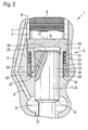
- FIG. 2 shows a further embodiment variant of the hydraulic proposed according to the invention Translator with a spring loaded on one of the booster piston Control chamber sleeve.
- the illustrated in Figure 2 embodiment of a fuel injector 1 includes the first booster piston 20 and the second piston part 23 having pressure booster 2.
- the pressure booster 2 is analogous to the embodiment shown in Figure 1 over actuated in an acted upon by system pressure cavity 4 actuator 5 is actuated.
- the actuator 5 is preferably a piezoactuator, the piezocrystals in stack form contains. When energized, the piezoelectric crystals of the actuator 5 change in the stacked arrangement recorded piezocrystals their longitudinal extent. This will make the hydraulic Pressure intensifier 2 actuated.
- nozzle inlet 9 From pressurized with system pressure fuel 7 cavity 4 extends a nozzle inlet 9 to a nozzle chamber 10.
- the nozzle chamber 10 encloses the injection valve member 11; from the nozzle chamber 10 branches an annular gap 13 to in Figure 2, not shown Injection openings from, over which with the injection valve member 11 open fuel can be injected into the combustion chamber of an internal combustion engine.
- a pressure stage 12 is formed on the injection valve member 11, at which when pressure is applied to the nozzle chamber 10 in the opening direction of the injection valve member 11 attacking force is generated.
- the first booster piston 20, the first end face 21 through the end face 8 of the actuator 5 is applied to a piston part 23 of an injection valve member 11 or a Push rod 35 centered.
- a first control chamber 24 is formed, which communicates via a through-passage 26 with the second Control room 27 is connected.
- the passage 26 opens on the one hand in the End face 25 of the piston member 23 and on the other hand in the region of the second control chamber 27th in the lateral surface of the piston part 23.
- the piston part 23, whose end face 25 limits the first control chamber 24, can directly on Injection valve member 11 may be formed, or on an injection valve member 11 actuated Push rod 35 may be formed.
- the control chamber sleeve 33 is acted upon by a spring 32.
- the spring 32 is supported on an am first booster piston 20 formed annular surface 31 and acts on the upper Front side of the control chamber sleeve 33.
- the opposite side of the control chamber sleeve 33 is formed as a biting edge 34.
- About the spring 32 ensures that the biting edge 34 of the control chamber sleeve 33 always sealing to the bottom surface 29 of the second control chamber 27 is employed and prevailing in the second control chamber 27, the system pressure different pressure, sealing against the system pressure level.
- the first translator piston 20 is acted upon along a guide 36 relative to the control chamber sleeve 33, due to the application by the spring element 32 always to the bottom surface 29 of the housing. 3 the fuel injector 1 remains employed, so that the second control chamber 27 is always sealed is.
- Fuel injector 1 can be provided, which has a self-centering structure of the Translator piston 20 and a piston part 23 of a pressure booster 2 has.
- a pressure booster 2 can in particular the pressure booster 2 of a fuel injector 1 for direct control an injection valve member 11 are used.
Landscapes
- Engineering & Computer Science (AREA)
- Chemical & Material Sciences (AREA)
- Combustion & Propulsion (AREA)
- Mechanical Engineering (AREA)
- General Engineering & Computer Science (AREA)
- Fuel-Injection Apparatus (AREA)
Abstract
Description
- Figur 1
- eine erste Ausführungsvariante des erfindungsgemäß vorgeschlagenen hydraulischen Übersetzers mit ineinandergefährten Übersetzerkolben und
- Figur 2
- eine zweite Ausführungsvariante der erfindungsgemäß vorgeschlagenen hydraulischen Übersetzungsanordnung mit an einem der Übersetzerkolben aufgenommener druckfederbeaufschlagter Steuerraumhülse.
- 1
- Kraftstoffinjektor
- 2
- Druckübersetzer
- 3
- Gehäuse
- 4
- Hohlraum
- 5
- Aktor
- 6
- Zulauf (Systemdruck)
- 7
- Kraftstoff
- 8
- Stirnfläche Aktor
- 9
- Düsenzulauf
- 10
- Düsenraum
- 11
- Einspritzventilglied
- 12
- Druckstufe
- 13
- Ringspalt
- 14
- brennraumseitiger Sitz
- 15
- Einspritzöffnung
- 20
- Übersetzerkolben
- 21
- erste Stirnfläche Übersetzerkolben
- 22
- Führungsabschnitt
- 23
- Kolbenteil Einspritzventilglied 11
- 24
- erster Steuerraum
- 25
- Stirnfläche Kolbenteil 23
- 26
- Verbindungskanal
- 27
- zweiter Steuerraum
- 28
- zweite Stirnfläche Kolbenteil 23
- 29
- Bodenfläche zweiter Steuerraum 27
- 30
- Einspritzöffnung
- 31
- Ringfläche Übersetzerkolben
- 32
- Federelement
- 33
- Steuerraumhülse
- 34
- Beißkante
- 35
- Druckstange
- 36
- Führungsabschnitt Steuerraumhülse
Claims (9)
- Kraftstoffinjektor für ein Hochdruckspeichereinspritzsystem mit einem Druckübersetzer (2), der einen Übersetzerkolben (20) enthält, der über einen Aktor (5) betätigt wird und mit einem Einspritzventilglied (11), welches von einem Düsenraum (10) umschlossen und mit unter Systemdruck stehenden Kraftstoff beaufschlagt ist, wobei das Einspritzventilglied (11) über den Druckübersetzer (2) betätigt wird, dadurch gekennzeichnet, dass der Übersetzerkolben (20) auf einem Kolbenteil (23) des Einspritzventilgliedes (11) oder einer Druckstange (35) zentriert ist.
- Kraftstoffinjektor gemäß Anspruch 1, dadurch gekennzeichnet, dass eine Seite des Übersetzerkolbens (20) mit einem Fußbereich des Aktors (5) verbunden ist.
- Kraftstoffinjektor gemäß Anspruch 1, dadurch gekennzeichnet, dass der Druckübersetzer (2) einen ersten Steuerraum (24) und einen zweiten Steuerraum (27) umfasst.
- Kraftstoffinjektor gemäß Anspruch 3, dadurch gekennzeichnet, dass der erste Steuerraum (24) und der zweite Steuerraum (27) über einen im Kolbenteil (23) ausgebildeten Verbindungskanal (26) verbunden sind.
- Kraftstoffinjektor gemäß Anspruch 1, dadurch gekennzeichnet, dass der Aktor (5) in einen mit Systemdruck beaufschlagten Hohlraum (4) des Gehäuses (3) des Kraftstoffinjektors (1) aufgenommen ist.
- Kraftstoffinjektor gemäß Anspruch 1, dadurch gekennzeichnet, dass der Übersetzerkolben (20) in einem Führungsabschnitt (22) des Gehäuses (3) geführt ist.
- Kraftstoffinjektor gemäß der Ansprüche 1 und 3, dadurch gekennzeichnet, dass am Mantel des Übersetzerkolbens (20) eine federbeaufschlagte Steuerraumhülse (33) aufgenommen ist, die den zweiten Steuerraum (27) gegen Systemdruck abdichtet.
- Kraftstoffinjektor gemäß Anspruch 7, dadurch gekennzeichnet, dass die Steuerraumhülse (33) eine Beißkante (34) aufweist, die an eine den zweiten Steuerraum (27) begrenzende Bodenfläche (29) angestellt ist.
- Kraftstoffinjektor gemäß Anspruch 3, dadurch gekennzeichnet, dass der zweite Steuerraum (27) durch eine zweite Stirnfläche (28) des Übersetzerkolbens (20), die Steuerraumhülse (33) und eine Bodenfläche (29) des Gehäuses (3) begrenzt ist.
Applications Claiming Priority (2)
| Application Number | Priority Date | Filing Date | Title |
|---|---|---|---|
| DE102004004006A DE102004004006A1 (de) | 2004-01-27 | 2004-01-27 | Integrierter hydraulischer Druckübersetzer für Kraftstoffinjektoren an Hochdruckspeichereinspritzsystemen |
| DE102004004006 | 2004-01-27 |
Publications (2)
| Publication Number | Publication Date |
|---|---|
| EP1559908A1 true EP1559908A1 (de) | 2005-08-03 |
| EP1559908B1 EP1559908B1 (de) | 2006-11-08 |
Family
ID=34638753
Family Applications (1)
| Application Number | Title | Priority Date | Filing Date |
|---|---|---|---|
| EP04105849A Expired - Lifetime EP1559908B1 (de) | 2004-01-27 | 2004-11-17 | Integrierter hydraulischer Druckübersetzer für Kraftstoffinjektoren an Hochdruckspeichereinspritzsystemen. |
Country Status (2)
| Country | Link |
|---|---|
| EP (1) | EP1559908B1 (de) |
| DE (2) | DE102004004006A1 (de) |
Cited By (4)
| Publication number | Priority date | Publication date | Assignee | Title |
|---|---|---|---|---|
| WO2007098975A1 (de) * | 2006-02-24 | 2007-09-07 | Robert Bosch Gmbh | Kraftstoffeinspritzvorrichtung für eine brennkraftmaschine |
| EP1831539B1 (de) * | 2004-12-23 | 2010-03-31 | Robert Bosch Gmbh | Kraftstoffinjektor mit direkter steuerung des einspritzventilgliedes |
| EP2642112A1 (de) * | 2012-03-19 | 2013-09-25 | Robert Bosch GmbH | Einspritzventil mit in seiner Öffnungsposition anschlagsfrei abbremsbarer Ventilnadel |
| US9523335B2 (en) | 2012-05-30 | 2016-12-20 | Caterpillar Motoren Gmbh & Co. Kg | Plunger for an internal combustion engine fuel pump |
Families Citing this family (2)
| Publication number | Priority date | Publication date | Assignee | Title |
|---|---|---|---|---|
| DE102005042786B4 (de) * | 2005-09-08 | 2009-04-16 | Siemens Ag | Kraftstoffinjektor mit hermetisch abgedichtetem Hydrauliksystem |
| DE102005054361A1 (de) * | 2005-11-15 | 2007-05-24 | Fev Motorentechnik Gmbh | Hochdruckkraftstoffinjektor |
Citations (4)
| Publication number | Priority date | Publication date | Assignee | Title |
|---|---|---|---|---|
| DE4306073C1 (de) * | 1993-02-26 | 1994-06-01 | Siemens Ag | Zumeßvorrichtung für Fluide |
| JPH10288117A (ja) * | 1997-04-18 | 1998-10-27 | Nissan Motor Co Ltd | エンジンの燃料噴射弁 |
| DE10060836C1 (de) * | 2000-12-07 | 2002-07-25 | Bosch Gmbh Robert | Druckgesteuerter CR Injektor mit gestuftem Öffnungs- und Schließverhalten |
| WO2004111434A1 (de) * | 2003-06-11 | 2004-12-23 | Robert Bosch Gmbh | Injektor für kraftstoff-einspritzsysteme von brennkraftmaschinen, insbesondere von direkteinspritzenden dieselmotoren |
-
2004
- 2004-01-27 DE DE102004004006A patent/DE102004004006A1/de not_active Withdrawn
- 2004-11-17 EP EP04105849A patent/EP1559908B1/de not_active Expired - Lifetime
- 2004-11-17 DE DE502004001947T patent/DE502004001947D1/de not_active Expired - Lifetime
Patent Citations (4)
| Publication number | Priority date | Publication date | Assignee | Title |
|---|---|---|---|---|
| DE4306073C1 (de) * | 1993-02-26 | 1994-06-01 | Siemens Ag | Zumeßvorrichtung für Fluide |
| JPH10288117A (ja) * | 1997-04-18 | 1998-10-27 | Nissan Motor Co Ltd | エンジンの燃料噴射弁 |
| DE10060836C1 (de) * | 2000-12-07 | 2002-07-25 | Bosch Gmbh Robert | Druckgesteuerter CR Injektor mit gestuftem Öffnungs- und Schließverhalten |
| WO2004111434A1 (de) * | 2003-06-11 | 2004-12-23 | Robert Bosch Gmbh | Injektor für kraftstoff-einspritzsysteme von brennkraftmaschinen, insbesondere von direkteinspritzenden dieselmotoren |
Non-Patent Citations (1)
| Title |
|---|
| PATENT ABSTRACTS OF JAPAN vol. 1999, no. 01 29 January 1999 (1999-01-29) * |
Cited By (7)
| Publication number | Priority date | Publication date | Assignee | Title |
|---|---|---|---|---|
| EP1831539B1 (de) * | 2004-12-23 | 2010-03-31 | Robert Bosch Gmbh | Kraftstoffinjektor mit direkter steuerung des einspritzventilgliedes |
| WO2007098975A1 (de) * | 2006-02-24 | 2007-09-07 | Robert Bosch Gmbh | Kraftstoffeinspritzvorrichtung für eine brennkraftmaschine |
| CN101389852B (zh) * | 2006-02-24 | 2011-07-27 | 罗伯特·博世有限公司 | 用于内燃机的燃料喷射装置 |
| RU2426002C2 (ru) * | 2006-02-24 | 2011-08-10 | Роберт Бош Гмбх | Устройство впрыскивания топлива для двигателя внутреннего сгорания |
| US8146839B2 (en) | 2006-02-24 | 2012-04-03 | Robert Bosch Gmbh | Fuel injection device for an internal combustion engine |
| EP2642112A1 (de) * | 2012-03-19 | 2013-09-25 | Robert Bosch GmbH | Einspritzventil mit in seiner Öffnungsposition anschlagsfrei abbremsbarer Ventilnadel |
| US9523335B2 (en) | 2012-05-30 | 2016-12-20 | Caterpillar Motoren Gmbh & Co. Kg | Plunger for an internal combustion engine fuel pump |
Also Published As
| Publication number | Publication date |
|---|---|
| EP1559908B1 (de) | 2006-11-08 |
| DE502004001947D1 (de) | 2006-12-21 |
| DE102004004006A1 (de) | 2005-08-11 |
Similar Documents
| Publication | Publication Date | Title |
|---|---|---|
| EP1714025B1 (de) | Kraftstoffinjektor mit direktgesteuertem einspritzventilglied | |
| EP1654455A1 (de) | Steuerventil für einen einen druckbesetzer enthaltend en kraftstoffinjektor | |
| EP1613856A1 (de) | Servoventilangesteuerter kraftstoffinjektor mit druckübersetzer | |
| EP1520099B1 (de) | Druckübersetzer kraftstoffinjektor mit schnellem druckabbau bei einspritzende | |
| EP1688611B1 (de) | Kraftstoffinjektor mit direkter Nadelsteuerung für eine Brennkraftmaschine | |
| EP1613855B1 (de) | Kraftstoffinjektor mit leckagefreiem servoventil | |
| EP1831540B1 (de) | Kraftstoffinjektor mit direkt angesteuertem einspritzventilglied | |
| DE10335059A1 (de) | Schaltventil für einen Kraftstoffinjektor mit Druckübersetzer | |
| DE102005015997A1 (de) | Kraftstoffinjektor mit direkter Steuerung des Einspritzventilgliedes | |
| DE10229413A1 (de) | Druckübersetzersteuerung durch Bewegung eines Einspritzventilgliedes | |
| EP1682769B1 (de) | Kraftstoffinjektor mit mehrteiligem, direktgesteuertem einspritzventilglied | |
| DE102008002416A1 (de) | Kraftstoffinjektor | |
| EP1559908B1 (de) | Integrierter hydraulischer Druckübersetzer für Kraftstoffinjektoren an Hochdruckspeichereinspritzsystemen. | |
| WO2005015000A1 (de) | Schaltventil mit druckausgleich für einen kraftstoffinjektor mit druckverstärker | |
| WO2007000371A1 (de) | Injektor mit zuschaltbarem druckübersetzer | |
| EP1908953B1 (de) | Kraftstoffeinspritzanlage | |
| WO2004042224A1 (de) | Kraftstoffeinspritzeinrichtung mit integriertem druckverstärker | |
| DE10152253B4 (de) | Ventil zum Steuern von Flüssigkeiten | |
| EP1792073A1 (de) | Einspritzdüse | |
| EP2133552B1 (de) | Kraftstoffinjektor | |
| DE102006050164A1 (de) | Kraftstoffinjektor mit hydraulischer Übersetzung | |
| WO2002090765A1 (de) | Injektor zum einspritzen von kraftstoff mit in reihe geschalteten steuerventilgliedern | |
| DE102006013704A1 (de) | Kraftstoffinjektor mit dynamischem Kraftstoffausgleich | |
| DE10338768A1 (de) | Kraftstoffeinspritzventil für Brennkraftmaschinen | |
| DE102006026398A1 (de) | Kraftstoffinjektor mit Servo-Unterstützung |
Legal Events
| Date | Code | Title | Description |
|---|---|---|---|
| PUAI | Public reference made under article 153(3) epc to a published international application that has entered the european phase |
Free format text: ORIGINAL CODE: 0009012 |
|
| AK | Designated contracting states |
Kind code of ref document: A1 Designated state(s): AT BE BG CH CY CZ DE DK EE ES FI FR GB GR HU IE IS IT LI LU MC NL PL PT RO SE SI SK TR |
|
| AX | Request for extension of the european patent |
Extension state: AL HR LT LV MK YU |
|
| 17P | Request for examination filed |
Effective date: 20060203 |
|
| AKX | Designation fees paid |
Designated state(s): DE FR GB IT |
|
| GRAP | Despatch of communication of intention to grant a patent |
Free format text: ORIGINAL CODE: EPIDOSNIGR1 |
|
| GRAS | Grant fee paid |
Free format text: ORIGINAL CODE: EPIDOSNIGR3 |
|
| GRAA | (expected) grant |
Free format text: ORIGINAL CODE: 0009210 |
|
| AK | Designated contracting states |
Kind code of ref document: B1 Designated state(s): DE FR GB IT |
|
| REG | Reference to a national code |
Ref country code: GB Ref legal event code: FG4D Free format text: NOT ENGLISH |
|
| REF | Corresponds to: |
Ref document number: 502004001947 Country of ref document: DE Date of ref document: 20061221 Kind code of ref document: P |
|
| GBT | Gb: translation of ep patent filed (gb section 77(6)(a)/1977) |
Effective date: 20070205 |
|
| ET | Fr: translation filed | ||
| PLBE | No opposition filed within time limit |
Free format text: ORIGINAL CODE: 0009261 |
|
| STAA | Information on the status of an ep patent application or granted ep patent |
Free format text: STATUS: NO OPPOSITION FILED WITHIN TIME LIMIT |
|
| 26N | No opposition filed |
Effective date: 20070809 |
|
| PGFP | Annual fee paid to national office [announced via postgrant information from national office to epo] |
Ref country code: IT Payment date: 20121126 Year of fee payment: 9 Ref country code: GB Payment date: 20121122 Year of fee payment: 9 |
|
| PGFP | Annual fee paid to national office [announced via postgrant information from national office to epo] |
Ref country code: FR Payment date: 20121217 Year of fee payment: 9 |
|
| GBPC | Gb: european patent ceased through non-payment of renewal fee |
Effective date: 20131117 |
|
| REG | Reference to a national code |
Ref country code: FR Ref legal event code: ST Effective date: 20140731 |
|
| PG25 | Lapsed in a contracting state [announced via postgrant information from national office to epo] |
Ref country code: IT Free format text: LAPSE BECAUSE OF NON-PAYMENT OF DUE FEES Effective date: 20131117 |
|
| PG25 | Lapsed in a contracting state [announced via postgrant information from national office to epo] |
Ref country code: FR Free format text: LAPSE BECAUSE OF NON-PAYMENT OF DUE FEES Effective date: 20131202 Ref country code: GB Free format text: LAPSE BECAUSE OF NON-PAYMENT OF DUE FEES Effective date: 20131117 |
|
| PGFP | Annual fee paid to national office [announced via postgrant information from national office to epo] |
Ref country code: DE Payment date: 20180125 Year of fee payment: 14 |
|
| REG | Reference to a national code |
Ref country code: DE Ref legal event code: R119 Ref document number: 502004001947 Country of ref document: DE |
|
| PG25 | Lapsed in a contracting state [announced via postgrant information from national office to epo] |
Ref country code: DE Free format text: LAPSE BECAUSE OF NON-PAYMENT OF DUE FEES Effective date: 20190601 |