EP1559981B1 - Wärmeübertrager aus runden profilierten Wärmeübertragunsplatten - Google Patents
Wärmeübertrager aus runden profilierten Wärmeübertragunsplatten Download PDFInfo
- Publication number
- EP1559981B1 EP1559981B1 EP05001668.2A EP05001668A EP1559981B1 EP 1559981 B1 EP1559981 B1 EP 1559981B1 EP 05001668 A EP05001668 A EP 05001668A EP 1559981 B1 EP1559981 B1 EP 1559981B1
- Authority
- EP
- European Patent Office
- Prior art keywords
- plates
- plate
- heat transfer
- heat exchanger
- pack
- Prior art date
- Legal status (The legal status is an assumption and is not a legal conclusion. Google has not performed a legal analysis and makes no representation as to the accuracy of the status listed.)
- Expired - Lifetime
Links
- 238000007789 sealing Methods 0.000 claims description 7
- 239000004744 fabric Substances 0.000 claims description 3
- 238000005192 partition Methods 0.000 claims description 3
- 230000002776 aggregation Effects 0.000 claims 1
- 238000004220 aggregation Methods 0.000 claims 1
- 210000001520 comb Anatomy 0.000 description 4
- 238000005516 engineering process Methods 0.000 description 3
- 238000004519 manufacturing process Methods 0.000 description 3
- 239000002184 metal Substances 0.000 description 3
- 230000004941 influx Effects 0.000 description 2
- 230000002093 peripheral effect Effects 0.000 description 2
- 238000003466 welding Methods 0.000 description 2
- 241001295925 Gegenes Species 0.000 description 1
- 238000004378 air conditioning Methods 0.000 description 1
- 230000000712 assembly Effects 0.000 description 1
- 238000000429 assembly Methods 0.000 description 1
- 230000015572 biosynthetic process Effects 0.000 description 1
- 230000009172 bursting Effects 0.000 description 1
- 238000004891 communication Methods 0.000 description 1
- 239000002131 composite material Substances 0.000 description 1
- 238000009434 installation Methods 0.000 description 1
- 238000000034 method Methods 0.000 description 1
- 239000003566 sealing material Substances 0.000 description 1
- 238000000926 separation method Methods 0.000 description 1
- 238000005476 soldering Methods 0.000 description 1
Images


Classifications
-
- F—MECHANICAL ENGINEERING; LIGHTING; HEATING; WEAPONS; BLASTING
- F28—HEAT EXCHANGE IN GENERAL
- F28D—HEAT-EXCHANGE APPARATUS, NOT PROVIDED FOR IN ANOTHER SUBCLASS, IN WHICH THE HEAT-EXCHANGE MEDIA DO NOT COME INTO DIRECT CONTACT
- F28D9/00—Heat-exchange apparatus having stationary plate-like or laminated conduit assemblies for both heat-exchange media, the media being in contact with different sides of a conduit wall
- F28D9/0012—Heat-exchange apparatus having stationary plate-like or laminated conduit assemblies for both heat-exchange media, the media being in contact with different sides of a conduit wall the apparatus having an annular form
- F28D9/0018—Heat-exchange apparatus having stationary plate-like or laminated conduit assemblies for both heat-exchange media, the media being in contact with different sides of a conduit wall the apparatus having an annular form without any annular circulation of the heat exchange media
-
- F—MECHANICAL ENGINEERING; LIGHTING; HEATING; WEAPONS; BLASTING
- F28—HEAT EXCHANGE IN GENERAL
- F28D—HEAT-EXCHANGE APPARATUS, NOT PROVIDED FOR IN ANOTHER SUBCLASS, IN WHICH THE HEAT-EXCHANGE MEDIA DO NOT COME INTO DIRECT CONTACT
- F28D9/00—Heat-exchange apparatus having stationary plate-like or laminated conduit assemblies for both heat-exchange media, the media being in contact with different sides of a conduit wall
- F28D9/0006—Heat-exchange apparatus having stationary plate-like or laminated conduit assemblies for both heat-exchange media, the media being in contact with different sides of a conduit wall the plate-like or laminated conduits being enclosed within a pressure vessel
-
- F—MECHANICAL ENGINEERING; LIGHTING; HEATING; WEAPONS; BLASTING
- F28—HEAT EXCHANGE IN GENERAL
- F28D—HEAT-EXCHANGE APPARATUS, NOT PROVIDED FOR IN ANOTHER SUBCLASS, IN WHICH THE HEAT-EXCHANGE MEDIA DO NOT COME INTO DIRECT CONTACT
- F28D9/00—Heat-exchange apparatus having stationary plate-like or laminated conduit assemblies for both heat-exchange media, the media being in contact with different sides of a conduit wall
- F28D9/0031—Heat-exchange apparatus having stationary plate-like or laminated conduit assemblies for both heat-exchange media, the media being in contact with different sides of a conduit wall the conduits for one heat-exchange medium being formed by paired plates touching each other
- F28D9/0043—Heat-exchange apparatus having stationary plate-like or laminated conduit assemblies for both heat-exchange media, the media being in contact with different sides of a conduit wall the conduits for one heat-exchange medium being formed by paired plates touching each other the plates having openings therein for circulation of at least one heat-exchange medium from one conduit to another
-
- F—MECHANICAL ENGINEERING; LIGHTING; HEATING; WEAPONS; BLASTING
- F28—HEAT EXCHANGE IN GENERAL
- F28F—DETAILS OF HEAT-EXCHANGE AND HEAT-TRANSFER APPARATUS, OF GENERAL APPLICATION
- F28F9/00—Casings; Header boxes; Auxiliary supports for elements; Auxiliary members within casings
- F28F9/007—Auxiliary supports for elements
- F28F9/0075—Supports for plates or plate assemblies
Definitions
- the invention relates to a heat exchanger made of round profiled heat transfer plates with passages for heat transfer between media of the same or different physical state, consisting of a plate package, which is formed from at least two joined heat transfer plate pairs consisting of two gas-tight welded to the flow heat transfer plates and two Closing plates with passages for flowing through the plate package medium, which limit the joined heat transfer plate pairs on both sides, wherein the adjacent heat transfer plate pairs and the limiting closure plates are gas-tight welded to the outer periphery to form a separate pressure chamber and a pressure-stable housing with shell side arranged passage openings for a second medium , which flows through the plate package shell side t, and end-side passage openings with connecting pieces, which are welded to the passage openings of the closure plates.
- a heat exchanger of the type mentioned in which at the periphery of the plate package fürfluß Adjusten for the shell side inflowing heat transfer medium are provided, which have an inner tube structure of the housing and are partially in communication with the plate package, wherein at least two of the flow guides are disposed opposite to an inner tube structure to the plate pack, which are supported against the inner wall of the surrounding housing.
- the portions of the flow guides having an inner tube structure and forming the inflow and outflow regions are connected to tubes which engage the inlet and outlet ports of the surrounding housing, at least one of the tubes being leak-proof against the inner wall of the inlet and / or Outlet neck is sealed metallic.
- a bypass-side inflow region formed in this way can prevent a bypass between the inner wall of the housing and the plate pack, for use in the high-pressure region it is necessary for the regions of the flow guides which communicate with the periphery of the plate pack to be counteracted by additional measures the housing inner wall are supported in order to achieve a corresponding pressure stability of the heat exchanger.
- the WO 02/16852 suggest that these areas are additionally filled with a non-flowing heat transfer medium.
- a plate heat exchanger in which the joined profiled heat transfer plates are permanently connected to the through holes by soldering to a plate package.
- the plates are provided with at least one opening, which form a fastener channel in the soldered plate package through which a clamping screw for fixing the plate heat exchanger extends to a support member or a mounting plate, wherein the clamping screw is used simultaneously for clamping the soldered plate package intercept occurring pressure differences.
- a trained plate heat exchanger is also completely unsuitable for the high pressure range and in a Temperaturbreich of -200 ° to + 900 °. But a shell-side influx of a medium is not possible by fully soldered execution.
- the object of the present invention is therefore to improve the heat exchangers mentioned at the outset, that the heat exchanger as a metallically sealed and wear-free compact heat exchanger for the high pressure range and for a temperature range of - 200 ° C to + 900 ° C cost for the intended use of prefabricated standard modules can be produced and fluidically designed so that the konzepiere heat transfer surface shell side influx of the plate package is used maximally for the heat transfer.
- the inventive feature combination creates the prerequisite that the heat exchanger can be inexpensively executed from prefabricated standard assemblies as metallically sealed and wear-free compact heat exchanger both in a fully welded embodiment and with a metallically sealed housing, for a wide industrial application, such as for the cold and air conditioning technology, power plant technology, building services, chem. Process technology, etc., at an operating temperature of - 200 ° C to + 900 ° C can be used without interference.
- the condition is given that the shell-side inflow in the production of a heat exchanger very can be inexpensively adapted to the optimum flow conditions of the jacket medium, which ensure a uniform mantel wornes flow of the plate package and thus maximum utilization of the designed heat transfer surface for the predetermined application.
- the assembly of the heat exchanger is very simplified and thus carried out very inexpensively , Rather, with the metallic sealing support of the U-shaped bends of the side plates against the inner diameter of the housing shell the shell-side bypass is prevented at the same time and the plate package itself is stably positioned in the housing shell.
- the metallic sealing of the shell-side opening angle is carried out with a gauze-like metal fabric, which is inserted in strips between the clamping bolts and under the side panels in the gaps between adjacent heat transfer plate pairs.
- the shell-side bypass can be effectively counteracted at the periphery of the plate pack and the sealing can be carried out with a thermally and chemically highly resistant sealing material, which is clearly fixed in position by the side plates.
- the package clamping plates in the area between the clamping bolts, which are covered by the side plates, approximately offset to the diameter of the plate package.
- each of the side plates consists of two partial side plates, wherein one of the partial side plates has a straight end, which is partially covered by the other part of the side sheet partially flat, which is provided with a Z-shaped end, which is against the inner diameter supported by the housing shell.
- the width is variable, whereby a problem-free adjustment of the side plates can be made to the surface to be covered during assembly. Consequently, the shell-side opening angle of the inflow region can be adjusted exclusively by the changed positioning of the limiting clamping bolts on the package clamping plates during manufacture exactly to the intended use of the heat exchanger so that a maximum flow through the jacket medium takes place and the designed heat transfer surface of the plate package optimal for heat transfer is being used.
- the service-free design of the heat exchanger makes it possible that advantageously the housing shell is welded to the end plates. In this way, a fully welded gas-tight compact heat exchanger can be provided in which leaks and leaks can be completely ruled out.
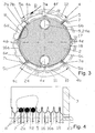
- the heat exchanger consists essentially of a plate pack 1 with closure plates 19, 19a, the package clamping plates 3, 3a, the clamping bolt 4 - 4x, the side plates 6, 6a or the Generalizingblechen 6b, 6c and 6d, 6e, the combs 5 - 5c, the metallic seals 11 and the housing shell 12 with the two end plates 13, 13a and at least two fixed to the housing shell 12 mantle 14, 14a and at least two fixed to the end plates 13, 13a plate-side connecting piece 23, 23a.
- the housing 21 is in the embodiment shown a vollversch spater pressure vessel consisting of the housing shell 12 and the two end plates 13; 13a with passage openings 25; 25a is formed, which are gas-tight welded to the housing shell 12 at the periphery.
- a vollversch spater pressure vessel consisting of the housing shell 12 and the two end plates 13; 13a with passage openings 25; 25a is formed, which are gas-tight welded to the housing shell 12 at the periphery.
- the passage opening 25 of the end plate 13 of the plate-side connecting piece 23 and at the passage opening 25 a of the end plate 13 a of the plate-side connecting piece 23 a is provided, each of the end plates 13; 13a and the package clamping plate 3, 3a penetrate and circumferentially with the end plate 13; 13a are connected.
- shell-side passage openings 15; 15a provided, to which the jacket pipe 14; 14a are welded gas-tight for the jacket medium.
- the plate pack 1 consists of a number of joined round profiled heat transfer plates 2 - 2x, which were determined thermally for the intended use and from the closure plates 19, 19a, which close the plate pack 1 at the ends.
- the heat transfer plates 2 - 2x are at the periphery of the passages to heat transfer plate pairs 16; 16a gas-tight welded and the respective adjacent heat transfer plate pairs 16; 16 are together with the closing closure plates 19; 19a at the outer periphery welded together gas-tight.
- the closure plates 19; 19a are formed with passage openings, which together with the passage openings of the heat transfer plates 2 - 2x the passageways 24; Form 24a through the plate pack 1.
- the ends of the plate-side connecting pieces 23, 23a welded gas-tight, the package clamping plate 3; 3a and the end plate 13; 13 a of the housing 21 penetrate.
- the plate pack 1 is on both sides by the package clamping plates 3; 3a with the passage openings 20; 20a limited, which are clamped by means of clamping bolts 4 - 4x.
- the clamping bolts 4 - 4 extend adjacent to the periphery of the plate pack 1 and are on both sides with package clamping plates 3; 3a under predetermined bias of the plate package with the package clamping plates 3; 3a welded.
- the shell-side opening angle ⁇ ; ⁇ 1 before the welding of the clamping bolt 4, 4b and 4a, 4c in a heat exchanger economically and individually adaptable to the designed power and the fluidic conditions of the jacket medium used. Consequently, the condition is thus created that the correspondingly available lateral surface of the plate pack 1 evenly is acted upon by the jacket medium, so that each heat exchanger for its application can be designed so that the designed heat transfer surface of the plate pack 1 is used optimally thermally.
- the running at the periphery of the plate pack 1 clamping bolt 4d, 4e are 90 ° to the center of the opening angle ⁇ ; ⁇ 1 offset and the clamping bolts 4f - 4x are in the range of the opening angle ⁇ , ⁇ 1 and are with the package clamping plates 3; 3a welded to further stabilize the plate pack 1.
- the clamping bolts 4f; 4x are rectangular in this particular case and at the same time serve to set the straight end 18 of the partial side panel 6c; 6f on the periphery of the disk pack 1.
- the metallic seals 8 are compared with the opening angles ⁇ ; ⁇ 1 of the shell-side Anström Schemes by comb plates 5, 5a and 5b, 5c position stabilized positioned, which engage in the gaps 22 of the adjacent heat transfer plate pairs 16, 16a and extend over the length of the plate pack 1.
- These comb plates 5; 5a; 5b; 5c are on the opposite side Side of the opening angle ⁇ ; ⁇ 1 parallel to the clamping bolt 4; 4a; 4b; 4c and 4c are on the clamping bolt; 4a; 4b; 4c welded.
- the combs of the comb plates 5; 5a; 5b; 5 c formed with a contour corresponding to the shape of the columns 22.
- the comb plates 5 - 5c are designed in a width which is supported on the inner wall of the housing 21 after installation of the heat exchanger.
- the pressure-stable position of the plate package 1 in the housing 21 can be additionally improved.
- the at the clamping bolt 4; 4a; 4b; 4c adjacent ends of the side panels 6; 6a and the partial side plates 6b; 6c; 6d; 6e are formed with congruent U-shaped angled portions 7, 7a and 7b, 7c, which are supported sealingly after assembly on the inner wall of the housing shell 12.
- the partial side plates 6c and 6e are each formed with a straight-running end 18 of the clamping bolt 4f; 4x and partly from a partial side panel 6d; 6b, which is provided with a Z-shaped end 17, covered.
- the Z-shaped end 17 of the partial side panels 6d; 6b is spaced apart from the plate pack 1 so that it is sealingly supported after assembly on the inner wall of the housing shell 12 and thus forms a further support point of the plate pack 1 against the inner wall of the housing shell 12, which further improves the positional stability and pressure stability of the plate pack 1 ,
- the partial side plates 6d, 6e and 6b, 6c namely that of one of the two cooperating partial side plates 6d; 6e and 6b, respectively; 6c has a straight end 18, that of the other part of the side panel 6d; 6c and 6b, respectively; 6c, the partial side plates 6d, 6e or 6b, 6c are individually adaptable to the region to be covered, which is determined by the selected opening angle ⁇ , ⁇ 1 of the shell-side inflow region.
- the described embodiment of the heat exchanger is designed Centerpposit.
- a metallic plate pass 9 and coat side a metallic jacket separation 10 is used in the passage 24 a of the plate pack 1.
- the metallic jacket partition 10 is slotted on the side facing the plate pack 1 side and placed on the junction of two heat transfer plate pairs 16, 16a and by the inserted metallic seals 6 in the columns 22 of the adjacent heat transfer plate pairs 16, 16 a sealed at the circumference of the plate pack 1 and fixed jacket side sealed against the inner wall of the housing shell 12 with a metallic seal 11.
- the inventively proposed and completely metallic sealed heat exchanger is almost service-free and thus suitable for the compact design in a fully welded design in the high pressure and high temperature range. But it can also be designed by the specific embodiment very economically from prefabricated standard modules to each purpose individually for optimum use of the designed heat transfer surface.
Landscapes
- Engineering & Computer Science (AREA)
- Physics & Mathematics (AREA)
- Thermal Sciences (AREA)
- Mechanical Engineering (AREA)
- General Engineering & Computer Science (AREA)
- Heat-Exchange Devices With Radiators And Conduit Assemblies (AREA)
Priority Applications (1)
| Application Number | Priority Date | Filing Date | Title |
|---|---|---|---|
| PL05001668T PL1559981T3 (pl) | 2004-01-30 | 2005-01-27 | Wymiennik ciepła z okrągłych profilowanych płytek przewodzących ciepło |
Applications Claiming Priority (2)
| Application Number | Priority Date | Filing Date | Title |
|---|---|---|---|
| DE102004004895 | 2004-01-30 | ||
| DE102004004895A DE102004004895B3 (de) | 2004-01-30 | 2004-01-30 | Wärmeübertrager aus runden profilierten Wärmeübertragungsplatten |
Publications (3)
| Publication Number | Publication Date |
|---|---|
| EP1559981A2 EP1559981A2 (de) | 2005-08-03 |
| EP1559981A3 EP1559981A3 (de) | 2012-05-30 |
| EP1559981B1 true EP1559981B1 (de) | 2013-07-03 |
Family
ID=34585412
Family Applications (1)
| Application Number | Title | Priority Date | Filing Date |
|---|---|---|---|
| EP05001668.2A Expired - Lifetime EP1559981B1 (de) | 2004-01-30 | 2005-01-27 | Wärmeübertrager aus runden profilierten Wärmeübertragunsplatten |
Country Status (6)
| Country | Link |
|---|---|
| EP (1) | EP1559981B1 (da) |
| DE (1) | DE102004004895B3 (da) |
| DK (1) | DK1559981T3 (da) |
| ES (1) | ES2429137T3 (da) |
| PL (1) | PL1559981T3 (da) |
| PT (1) | PT1559981E (da) |
Families Citing this family (8)
| Publication number | Priority date | Publication date | Assignee | Title |
|---|---|---|---|---|
| US9080815B2 (en) | 2008-06-18 | 2015-07-14 | Gesmex Gmbh | Conversion set for a tube bundle heat exchanger |
| US20110024082A1 (en) * | 2009-05-09 | 2011-02-03 | Tranter, Inc. | Heat exchanger with accessible core |
| DE102009023929A1 (de) | 2009-06-04 | 2010-12-09 | Stürzebecher, Wolfgang, Dr. | Absorptionskälteaggregat |
| EP2944912B1 (en) | 2014-05-13 | 2016-12-14 | Alfa Laval Corporate AB | Plate heat exchanger |
| KR20160147475A (ko) * | 2015-06-15 | 2016-12-23 | 현대자동차주식회사 | 캔형 열교환기 |
| CN108645255A (zh) * | 2018-07-11 | 2018-10-12 | 广东捷玛节能科技股份有限公司 | 一种可拆式气气板式热交换器 |
| DK180416B1 (en) * | 2019-11-04 | 2021-04-22 | Danfoss As | Plate-and-shell heat exchanger and a channel blocking plate for a plate-and-shell heat exchanger |
| CN114570692B (zh) * | 2022-02-12 | 2023-06-16 | 江苏高创风电设备有限公司 | 一种液压元件清洗设备 |
Family Cites Families (6)
| Publication number | Priority date | Publication date | Assignee | Title |
|---|---|---|---|---|
| GB203160A (en) * | 1922-08-15 | 1923-09-06 | Burmah Oil Co Ltd | Improved apparatus for cooling oil or other liquids |
| US1669062A (en) * | 1924-10-28 | 1928-05-08 | Menzel Ag | Heat-exchange apparatus |
| FR2719369B1 (fr) * | 1994-04-29 | 1996-07-19 | Framatome Sa | Echangeur thermique à plaques. |
| SE502638C2 (sv) * | 1994-05-18 | 1995-11-27 | Tetra Laval Holdings & Finance | Plattvärmeväxlare med permanent sammanfogade moduler |
| SE9504586D0 (sv) * | 1995-12-21 | 1995-12-21 | Tetra Laval Holdings & Finance | Plattvärmeväxlare |
| FI114738B (fi) * | 2000-08-23 | 2004-12-15 | Vahterus Oy | Levyrakenteinen lämmönvaihdin |
-
2004
- 2004-01-30 DE DE102004004895A patent/DE102004004895B3/de not_active Expired - Fee Related
-
2005
- 2005-01-27 ES ES05001668T patent/ES2429137T3/es not_active Expired - Lifetime
- 2005-01-27 EP EP05001668.2A patent/EP1559981B1/de not_active Expired - Lifetime
- 2005-01-27 DK DK05001668.2T patent/DK1559981T3/da active
- 2005-01-27 PT PT50016682T patent/PT1559981E/pt unknown
- 2005-01-27 PL PL05001668T patent/PL1559981T3/pl unknown
Also Published As
| Publication number | Publication date |
|---|---|
| EP1559981A2 (de) | 2005-08-03 |
| DK1559981T3 (da) | 2013-10-14 |
| EP1559981A3 (de) | 2012-05-30 |
| DE102004004895B3 (de) | 2005-06-16 |
| PT1559981E (pt) | 2013-10-09 |
| ES2429137T3 (es) | 2013-11-13 |
| PL1559981T3 (pl) | 2013-12-31 |
Similar Documents
| Publication | Publication Date | Title |
|---|---|---|
| EP2304370B1 (de) | Umrüstsatz für einen rohrbündelwärmetauscher | |
| EP1654508B2 (de) | Wärmeübertrager sowie verfahren zu dessen herstellung | |
| DE69409647T2 (de) | Plattenwärmetauscher | |
| EP0199321B1 (de) | Wärmetauscher | |
| EP1400772B1 (de) | Plattenwärmeübertrager | |
| DE102006048305A1 (de) | Plattenwärmetauscher | |
| EP1459026A1 (de) | W rme bertrager, insbesondere f r ein kraftfahrzeu g | |
| DE102007043231A1 (de) | U-förmiger Kühler | |
| EP2136175B1 (de) | Wärmeübertragungsplatte, Plattenpaar, Plattenpaket und Kompaktplattenwärmeüberträger sowie Verfahren zur Herstellung eines Kompaktplattenwärmeüberträgers | |
| EP1559981B1 (de) | Wärmeübertrager aus runden profilierten Wärmeübertragunsplatten | |
| DE69416037T2 (de) | Wärmetauscher | |
| DE102004002252A1 (de) | Wärmeübertrager für Fahrzeuge | |
| EP2795219A2 (de) | Modularer wärmetauscher | |
| EP1477761B1 (de) | Platten-Wärmeübertrager | |
| EP1769207B1 (de) | Platten-wärmetauscher | |
| DE19654365A1 (de) | Plattenwärmeübertrager | |
| EP1936311B1 (de) | Kompaktplattenwärmeübertrager | |
| EP2339280B1 (de) | Kompaktplattenwärmeübertrager | |
| DE19547928C2 (de) | Plattenwärmetauscher | |
| DE102004022433B4 (de) | Profilierte Wärmeübertragungsplatte für einen geschweissten Wärmeüberträger | |
| EP1815204B1 (de) | Rohrbündelhochdruckwärmetauscher | |
| DE10236665A1 (de) | Gas-Flüssigkeits-Wärmetauscher und damit ausgerüsteter Boiler | |
| EP2161526A2 (de) | Verfahren zum Herstellen eines Plattenwärmetauschers, sowie nach diesem Verfahren hergestellter Plattenwärmetauscher | |
| AT405444B (de) | Heizeinrichtung mit einem im wesentlichen zylinderförmigen brenner | |
| EP1936310A1 (de) | Kompaktplattenwärmeübertrager |
Legal Events
| Date | Code | Title | Description |
|---|---|---|---|
| PUAI | Public reference made under article 153(3) epc to a published international application that has entered the european phase |
Free format text: ORIGINAL CODE: 0009012 |
|
| AK | Designated contracting states |
Kind code of ref document: A2 Designated state(s): AT BE BG CH CY CZ DE DK EE ES FI FR GB GR HU IE IS IT LI LT LU MC NL PL PT RO SE SI SK TR |
|
| AX | Request for extension of the european patent |
Extension state: AL BA HR LV MK YU |
|
| RAP1 | Party data changed (applicant data changed or rights of an application transferred) |
Owner name: TRANTER PRESSKO GMBH |
|
| PUAL | Search report despatched |
Free format text: ORIGINAL CODE: 0009013 |
|
| AK | Designated contracting states |
Kind code of ref document: A3 Designated state(s): AT BE BG CH CY CZ DE DK EE ES FI FR GB GR HU IE IS IT LI LT LU MC NL PL PT RO SE SI SK TR |
|
| AX | Request for extension of the european patent |
Extension state: AL BA HR LV MK YU |
|
| RIC1 | Information provided on ipc code assigned before grant |
Ipc: F28D 9/00 20060101AFI20120426BHEP |
|
| 17P | Request for examination filed |
Effective date: 20121130 |
|
| AKX | Designation fees paid |
Designated state(s): AT BE BG CH CY CZ DE DK EE ES FI FR GB GR HU IE IS IT LI LT LU MC NL PL PT RO SE SI SK TR |
|
| GRAP | Despatch of communication of intention to grant a patent |
Free format text: ORIGINAL CODE: EPIDOSNIGR1 |
|
| RAP1 | Party data changed (applicant data changed or rights of an application transferred) |
Owner name: TRANTER GMBH |
|
| GRAS | Grant fee paid |
Free format text: ORIGINAL CODE: EPIDOSNIGR3 |
|
| GRAA | (expected) grant |
Free format text: ORIGINAL CODE: 0009210 |
|
| AK | Designated contracting states |
Kind code of ref document: B1 Designated state(s): AT BE BG CH CY CZ DE DK EE ES FI FR GB GR HU IE IS IT LI LT LU MC NL PL PT RO SE SI SK TR |
|
| REG | Reference to a national code |
Ref country code: GB Ref legal event code: FG4D Free format text: NOT ENGLISH |
|
| REG | Reference to a national code |
Ref country code: DE Ref legal event code: R081 Ref document number: 502005013800 Country of ref document: DE Owner name: TRANTER, INC., WICHITA FALLS, US Free format text: FORMER OWNER: PRESSKO AG, 06556 ARTERN, DE |
|
| REG | Reference to a national code |
Ref country code: CH Ref legal event code: EP Ref country code: AT Ref legal event code: REF Ref document number: 620020 Country of ref document: AT Kind code of ref document: T Effective date: 20130715 |
|
| REG | Reference to a national code |
Ref country code: IE Ref legal event code: FG4D Free format text: LANGUAGE OF EP DOCUMENT: GERMAN |
|
| REG | Reference to a national code |
Ref country code: DE Ref legal event code: R096 Ref document number: 502005013800 Country of ref document: DE Effective date: 20130829 |
|
| REG | Reference to a national code |
Ref country code: CH Ref legal event code: NV Representative=s name: E. BLUM AND CO. AG PATENT- UND MARKENANWAELTE , CH |
|
| REG | Reference to a national code |
Ref country code: PT Ref legal event code: SC4A Free format text: AVAILABILITY OF NATIONAL TRANSLATION Effective date: 20131001 |
|
| REG | Reference to a national code |
Ref country code: DK Ref legal event code: T3 Effective date: 20131007 Ref country code: DK Ref legal event code: T3 |
|
| REG | Reference to a national code |
Ref country code: SE Ref legal event code: TRGR |
|
| PG25 | Lapsed in a contracting state [announced via postgrant information from national office to epo] |
Ref country code: SI Free format text: LAPSE BECAUSE OF FAILURE TO SUBMIT A TRANSLATION OF THE DESCRIPTION OR TO PAY THE FEE WITHIN THE PRESCRIBED TIME-LIMIT Effective date: 20130703 |
|
| REG | Reference to a national code |
Ref country code: NL Ref legal event code: T3 |
|
| REG | Reference to a national code |
Ref country code: ES Ref legal event code: FG2A Ref document number: 2429137 Country of ref document: ES Kind code of ref document: T3 Effective date: 20131113 |
|
| REG | Reference to a national code |
Ref country code: LT Ref legal event code: MG4D |
|
| REG | Reference to a national code |
Ref country code: PL Ref legal event code: T3 |
|
| PG25 | Lapsed in a contracting state [announced via postgrant information from national office to epo] |
Ref country code: CY Free format text: LAPSE BECAUSE OF FAILURE TO SUBMIT A TRANSLATION OF THE DESCRIPTION OR TO PAY THE FEE WITHIN THE PRESCRIBED TIME-LIMIT Effective date: 20130703 Ref country code: LT Free format text: LAPSE BECAUSE OF FAILURE TO SUBMIT A TRANSLATION OF THE DESCRIPTION OR TO PAY THE FEE WITHIN THE PRESCRIBED TIME-LIMIT Effective date: 20130703 Ref country code: IS Free format text: LAPSE BECAUSE OF FAILURE TO SUBMIT A TRANSLATION OF THE DESCRIPTION OR TO PAY THE FEE WITHIN THE PRESCRIBED TIME-LIMIT Effective date: 20131103 |
|
| PG25 | Lapsed in a contracting state [announced via postgrant information from national office to epo] |
Ref country code: GR Free format text: LAPSE BECAUSE OF FAILURE TO SUBMIT A TRANSLATION OF THE DESCRIPTION OR TO PAY THE FEE WITHIN THE PRESCRIBED TIME-LIMIT Effective date: 20131004 |
|
| PG25 | Lapsed in a contracting state [announced via postgrant information from national office to epo] |
Ref country code: EE Free format text: LAPSE BECAUSE OF FAILURE TO SUBMIT A TRANSLATION OF THE DESCRIPTION OR TO PAY THE FEE WITHIN THE PRESCRIBED TIME-LIMIT Effective date: 20130703 Ref country code: SK Free format text: LAPSE BECAUSE OF FAILURE TO SUBMIT A TRANSLATION OF THE DESCRIPTION OR TO PAY THE FEE WITHIN THE PRESCRIBED TIME-LIMIT Effective date: 20130703 Ref country code: RO Free format text: LAPSE BECAUSE OF FAILURE TO SUBMIT A TRANSLATION OF THE DESCRIPTION OR TO PAY THE FEE WITHIN THE PRESCRIBED TIME-LIMIT Effective date: 20130703 |
|
| PLBE | No opposition filed within time limit |
Free format text: ORIGINAL CODE: 0009261 |
|
| STAA | Information on the status of an ep patent application or granted ep patent |
Free format text: STATUS: NO OPPOSITION FILED WITHIN TIME LIMIT |
|
| 26N | No opposition filed |
Effective date: 20140404 |
|
| REG | Reference to a national code |
Ref country code: DE Ref legal event code: R097 Ref document number: 502005013800 Country of ref document: DE Effective date: 20140404 |
|
| PG25 | Lapsed in a contracting state [announced via postgrant information from national office to epo] |
Ref country code: LU Free format text: LAPSE BECAUSE OF FAILURE TO SUBMIT A TRANSLATION OF THE DESCRIPTION OR TO PAY THE FEE WITHIN THE PRESCRIBED TIME-LIMIT Effective date: 20140127 Ref country code: MC Free format text: LAPSE BECAUSE OF FAILURE TO SUBMIT A TRANSLATION OF THE DESCRIPTION OR TO PAY THE FEE WITHIN THE PRESCRIBED TIME-LIMIT Effective date: 20130703 |
|
| REG | Reference to a national code |
Ref country code: IE Ref legal event code: MM4A |
|
| PG25 | Lapsed in a contracting state [announced via postgrant information from national office to epo] |
Ref country code: IE Free format text: LAPSE BECAUSE OF NON-PAYMENT OF DUE FEES Effective date: 20140127 |
|
| REG | Reference to a national code |
Ref country code: FR Ref legal event code: PLFP Year of fee payment: 12 |
|
| PG25 | Lapsed in a contracting state [announced via postgrant information from national office to epo] |
Ref country code: BG Free format text: LAPSE BECAUSE OF FAILURE TO SUBMIT A TRANSLATION OF THE DESCRIPTION OR TO PAY THE FEE WITHIN THE PRESCRIBED TIME-LIMIT Effective date: 20130703 |
|
| PG25 | Lapsed in a contracting state [announced via postgrant information from national office to epo] |
Ref country code: HU Free format text: LAPSE BECAUSE OF FAILURE TO SUBMIT A TRANSLATION OF THE DESCRIPTION OR TO PAY THE FEE WITHIN THE PRESCRIBED TIME-LIMIT; INVALID AB INITIO Effective date: 20050127 Ref country code: TR Free format text: LAPSE BECAUSE OF FAILURE TO SUBMIT A TRANSLATION OF THE DESCRIPTION OR TO PAY THE FEE WITHIN THE PRESCRIBED TIME-LIMIT Effective date: 20130703 |
|
| REG | Reference to a national code |
Ref country code: FR Ref legal event code: PLFP Year of fee payment: 13 |
|
| PGFP | Annual fee paid to national office [announced via postgrant information from national office to epo] |
Ref country code: CH Payment date: 20161229 Year of fee payment: 13 Ref country code: CZ Payment date: 20161220 Year of fee payment: 13 |
|
| PGFP | Annual fee paid to national office [announced via postgrant information from national office to epo] |
Ref country code: ES Payment date: 20161222 Year of fee payment: 13 Ref country code: BE Payment date: 20161215 Year of fee payment: 13 |
|
| PGFP | Annual fee paid to national office [announced via postgrant information from national office to epo] |
Ref country code: NL Payment date: 20170117 Year of fee payment: 13 |
|
| PGFP | Annual fee paid to national office [announced via postgrant information from national office to epo] |
Ref country code: SE Payment date: 20170111 Year of fee payment: 13 Ref country code: FR Payment date: 20170126 Year of fee payment: 13 |
|
| PGFP | Annual fee paid to national office [announced via postgrant information from national office to epo] |
Ref country code: PL Payment date: 20170123 Year of fee payment: 13 Ref country code: AT Payment date: 20170109 Year of fee payment: 13 Ref country code: DK Payment date: 20170124 Year of fee payment: 13 Ref country code: PT Payment date: 20170102 Year of fee payment: 13 |
|
| PGFP | Annual fee paid to national office [announced via postgrant information from national office to epo] |
Ref country code: IT Payment date: 20170112 Year of fee payment: 13 |
|
| REG | Reference to a national code |
Ref country code: DE Ref legal event code: R082 Ref document number: 502005013800 Country of ref document: DE Representative=s name: HWP INTELLECTUAL PROPERTY, DE |
|
| REG | Reference to a national code |
Ref country code: DE Ref legal event code: R082 Ref document number: 502005013800 Country of ref document: DE Representative=s name: HWP INTELLECTUAL PROPERTY, DE Ref country code: DE Ref legal event code: R081 Ref document number: 502005013800 Country of ref document: DE Owner name: TRANTER, INC., WICHITA FALLS, US Free format text: FORMER OWNER: TRANTER GMBH, 06556 ARTERN, DE |
|
| REG | Reference to a national code |
Ref country code: GB Ref legal event code: 732E Free format text: REGISTERED BETWEEN 20180621 AND 20180627 |
|
| REG | Reference to a national code |
Ref country code: DK Ref legal event code: EBP Effective date: 20180131 |
|
| REG | Reference to a national code |
Ref country code: SE Ref legal event code: EUG |
|
| REG | Reference to a national code |
Ref country code: CH Ref legal event code: PL |
|
| REG | Reference to a national code |
Ref country code: NL Ref legal event code: MM Effective date: 20180201 |
|
| REG | Reference to a national code |
Ref country code: AT Ref legal event code: MM01 Ref document number: 620020 Country of ref document: AT Kind code of ref document: T Effective date: 20180127 |
|
| PG25 | Lapsed in a contracting state [announced via postgrant information from national office to epo] |
Ref country code: FR Free format text: LAPSE BECAUSE OF NON-PAYMENT OF DUE FEES Effective date: 20180131 Ref country code: PT Free format text: LAPSE BECAUSE OF NON-PAYMENT OF DUE FEES Effective date: 20180727 Ref country code: SE Free format text: LAPSE BECAUSE OF NON-PAYMENT OF DUE FEES Effective date: 20180128 |
|
| REG | Reference to a national code |
Ref country code: FR Ref legal event code: ST Effective date: 20180928 |
|
| REG | Reference to a national code |
Ref country code: BE Ref legal event code: MM Effective date: 20180131 |
|
| PG25 | Lapsed in a contracting state [announced via postgrant information from national office to epo] |
Ref country code: CZ Free format text: LAPSE BECAUSE OF NON-PAYMENT OF DUE FEES Effective date: 20180127 Ref country code: BE Free format text: LAPSE BECAUSE OF NON-PAYMENT OF DUE FEES Effective date: 20180131 Ref country code: LI Free format text: LAPSE BECAUSE OF NON-PAYMENT OF DUE FEES Effective date: 20180131 Ref country code: CH Free format text: LAPSE BECAUSE OF NON-PAYMENT OF DUE FEES Effective date: 20180131 Ref country code: AT Free format text: LAPSE BECAUSE OF NON-PAYMENT OF DUE FEES Effective date: 20180127 Ref country code: NL Free format text: LAPSE BECAUSE OF NON-PAYMENT OF DUE FEES Effective date: 20180201 |
|
| PG25 | Lapsed in a contracting state [announced via postgrant information from national office to epo] |
Ref country code: DK Free format text: LAPSE BECAUSE OF NON-PAYMENT OF DUE FEES Effective date: 20180131 |
|
| PG25 | Lapsed in a contracting state [announced via postgrant information from national office to epo] |
Ref country code: IT Free format text: LAPSE BECAUSE OF NON-PAYMENT OF DUE FEES Effective date: 20180127 |
|
| PG25 | Lapsed in a contracting state [announced via postgrant information from national office to epo] |
Ref country code: PL Free format text: LAPSE BECAUSE OF NON-PAYMENT OF DUE FEES Effective date: 20180127 |
|
| REG | Reference to a national code |
Ref country code: ES Ref legal event code: FD2A Effective date: 20190731 |
|
| PG25 | Lapsed in a contracting state [announced via postgrant information from national office to epo] |
Ref country code: ES Free format text: LAPSE BECAUSE OF NON-PAYMENT OF DUE FEES Effective date: 20180128 |
|
| P01 | Opt-out of the competence of the unified patent court (upc) registered |
Effective date: 20230524 |
|
| P02 | Opt-out of the competence of the unified patent court (upc) changed |
Effective date: 20230530 |
|
| REG | Reference to a national code |
Ref country code: DE Ref legal event code: R081 Ref document number: 502005013800 Country of ref document: DE Owner name: TRANTER, INC., HOUSTON, US Free format text: FORMER OWNER: TRANTER, INC., WICHITA FALLS, TEX., US |
|
| PGFP | Annual fee paid to national office [announced via postgrant information from national office to epo] |
Ref country code: FI Payment date: 20240125 Year of fee payment: 20 Ref country code: DE Payment date: 20240129 Year of fee payment: 20 Ref country code: GB Payment date: 20240129 Year of fee payment: 20 |
|
| REG | Reference to a national code |
Ref country code: DE Ref legal event code: R071 Ref document number: 502005013800 Country of ref document: DE |
|
| REG | Reference to a national code |
Ref country code: GB Ref legal event code: PE20 Expiry date: 20250126 |
|
| PG25 | Lapsed in a contracting state [announced via postgrant information from national office to epo] |
Ref country code: GB Free format text: LAPSE BECAUSE OF EXPIRATION OF PROTECTION Effective date: 20250126 |