EP1559990A2 - Système de mesure de coordonnées et methode pour corriger les coordonnées mesurées avec un appareil de mesure de coordonnées - Google Patents
Système de mesure de coordonnées et methode pour corriger les coordonnées mesurées avec un appareil de mesure de coordonnées Download PDFInfo
- Publication number
- EP1559990A2 EP1559990A2 EP05001487A EP05001487A EP1559990A2 EP 1559990 A2 EP1559990 A2 EP 1559990A2 EP 05001487 A EP05001487 A EP 05001487A EP 05001487 A EP05001487 A EP 05001487A EP 1559990 A2 EP1559990 A2 EP 1559990A2
- Authority
- EP
- European Patent Office
- Prior art keywords
- coordinate measuring
- work
- measured
- measuring machine
- weight
- Prior art date
- Legal status (The legal status is an assumption and is not a legal conclusion. Google has not performed a legal analysis and makes no representation as to the accuracy of the status listed.)
- Withdrawn
Links
- 238000000034 method Methods 0.000 title claims description 20
- 230000003287 optical effect Effects 0.000 claims description 11
- 238000005259 measurement Methods 0.000 description 26
- 239000000523 sample Substances 0.000 description 11
- 230000006870 function Effects 0.000 description 4
- 238000000926 separation method Methods 0.000 description 3
- 239000013598 vector Substances 0.000 description 3
- 238000001514 detection method Methods 0.000 description 2
- 238000010586 diagram Methods 0.000 description 2
- 230000003068 static effect Effects 0.000 description 2
- 230000003746 surface roughness Effects 0.000 description 2
- 238000006243 chemical reaction Methods 0.000 description 1
- 230000006866 deterioration Effects 0.000 description 1
- 230000000694 effects Effects 0.000 description 1
- 238000002360 preparation method Methods 0.000 description 1
- 238000005096 rolling process Methods 0.000 description 1
Images


Classifications
-
- G—PHYSICS
- G01—MEASURING; TESTING
- G01B—MEASURING LENGTH, THICKNESS OR SIMILAR LINEAR DIMENSIONS; MEASURING ANGLES; MEASURING AREAS; MEASURING IRREGULARITIES OF SURFACES OR CONTOURS
- G01B21/00—Measuring arrangements or details thereof, where the measuring technique is not covered by the other groups of this subclass, unspecified or not relevant
- G01B21/02—Measuring arrangements or details thereof, where the measuring technique is not covered by the other groups of this subclass, unspecified or not relevant for measuring length, width, or thickness
- G01B21/04—Measuring arrangements or details thereof, where the measuring technique is not covered by the other groups of this subclass, unspecified or not relevant for measuring length, width, or thickness by measuring coordinates of points
- G01B21/045—Correction of measurements
Definitions
- the present invention relates to a method of correcting coordinates measured in a coordinate measuring machine. More particularly, it relates to a coordinate measuring system and method of correcting measured coordinates when a work with a weight is mounted on a base in a coordinate measuring machine.
- a variety of probes are employed in a coordinate measuring machine for measurements within a scale coordinate system, which includes reference scales arranged along axes that configure a three-dimensional measuring space.
- a structure thereof is required to have a higher static stiffness.
- Introduction of a software spatial precision correcting technology can reduce geometrical errors as low as possible to support higher precision.
- the coordinate measuring machine has geometrical errors, including scale errors, straightness errors, and angular errors such as pitching and yawing on axes within an orthogonal coordinate system in a kinematic model, as shown in Fig. 4. These errors are grouped as follows with a total of 21 error factors. Scale errors on axes 3 Horizontal straightness errors on axes 3 Vertical straightness errors on axes 3 Pitching errors on axes 3 Yawing errors on axes 3 Rolling errors on axes 3 Angular errors between axes 3
- a base also serving as a Y-axis motion guide plays a particularly important role in geometrical errors.
- Volumetric compensation can be utilized to provide CMM with high precision.
- the base if the base also serving as the Y-axis motion guide has a geometrical error, the base deforms when a user work is mounted thereon.
- the Y-axis motion guide is given a variation in geometrical precision, which leads to deterioration of CMM precision. Therefore, the base is designed to have a larger thickness in the art to improve the static stiffness of the base to increase the user' maximum loading weight. Accordingly, consideration is required for the thickness of the base on a basis of the maximum loading weight for a user work. This results in a longer delivery time and a larger cost.
- the recent increased use in measurement of large mold works desires CMM capable of measuring a 5 ton-10 ton work.
- the present invention has been made in consideration of such the point and accordingly has an object to provide a coordinate measuring machine capable of achieving measurements with high precision depending on user works and method of correcting a measuring space without alternation of the thickness of the base.
- a first aspect of the present invention provides a method of correcting coordinates measured in a coordinate measuring machine, comprising the steps of: storing compensation parameters per a weight of a work in a storage unit, the compensation parameters being derived from geometrical errors in a coordinate measuring machine, the geometrical errors being measured while works with various weights are mounted on the coordinate measuring machine; entering a weight of a work to be measured; reading from said storage unit a compensation parameter corresponding to said weight of said work entered at the previous step; and correcting measured coordinates of said work to be measured based on said compensation parameter read at the previous step.
- a second aspect of the present invention provides a coordinate measuring system, comprising: a coordinate measuring machine configured to measure a work to be measured mounted on a base within a three-dimensional measuring space; a controller operative to drive-control the coordinate measuring machine and fetch a necessary measured value from the coordinate measuring machine; and a host computer operative to process the measured value fetched through the controller.
- the coordinate measuring system further comprises a storage unit configured to store compensation parameters per a weight of a work derived from geometrical errors in the coordinate measuring machine, the geometrical errors being measured while works with various weights are mounted on a base of the coordinate measuring machine; and an input unit configured to enter weight information of the work. In this case, measured coordinates of the work to be measured are corrected based on the entered weight information of the work and the compensation parameters stored in the storage unit.
- the storage unit may be provided in the controller.
- the controller is operative to correct the measured coordinates of the work to be measured by switching among the compensation parameters based on the entered weight information of the work.
- the storage unit may also be provided in the host computer.
- the host computer is operative to send a compensation parameter corresponding to the weight of the work based on the entered weight information of the work, and the controller is operative to correct the measured coordinates of the work to be measured based on the compensation parameter received from the host computer.
- the input unit may be manually operative to enter the weight information of the work into the host computer.
- it may include a weight counter integrated in the coordinate measuring machine, and a unit operative to send the weight information of the work detected at the weight counter to the host computer.
- the base of the coordinate measuring machine may also serve as a Y-axis motion guide, and the geometrical errors may contain a Y-axis angular error caused by deformation of the base.
- geometrical errors in a coordinate measuring machine are measured while works with various weights are mounted on the coordinate measuring machine.
- Compensation parameters are derived from measured results per a weight of a work and stored.
- a compensation parameter corresponding to a weight of a work to be measured is appropriately read out to correct measured coordinates of the work to be measured. Accordingly, coordinate values can be corrected precisely even if the work weight deforms the base. Thus, it is possible to achieve measurements with high precision depending on user works without alternation of the thickness of the base.
- the coordinate measuring machine in this specification is not limited to one measuring coordinates. It may be one measuring surface texture. It also includes a surface roughness measuring machine, an undulation measuring machine, a profile measuring machine, a roundness measuring machine, and a straightness measuring machine.
- Fig. 1 is a block diagram illustrating a configuration of a CNC (Computerized Numerical Control) coordinate measuring system according to an embodiment of the present invention.
- CNC Computerized Numerical Control
- the CNC coordinate measuring system comprises a coordinate measuring machine 1, a controller 2 operative to drive-control the coordinate measuring machine 1 and fetch a necessary measured value from the coordinate measuring machine 1, and a host computer 3 operative to process the measured value fetched through the controller 2.
- the coordinate measuring machine 1 includes a weight counter 1a for measuring a weight of a work, and a transmitter 1b for sending the weight data to the host computer 3.
- the controller 2 includes a memory device 2a for storing data.
- the host computer 3 includes a memory device 3a for storing data and an input device 3b.
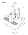
- the coordinate measuring machine 1 may be configured as shown in Fig. 2.
- a base 12 On a vibration isolating stand 11, a base 12 is mounted such that the upper surface thereof serves as a base plane coincident with a horizontal plane.
- a pair of beam supports 13a and 13b stand up from both ends of the base 12 such that the upper ends of the beam supports support a beam 14 extending in the X-axis direction.
- a Y-axis driving mechanism 15 drives the lower end of the beam support 13a in the Y-axis direction.
- An air bearing is employed to support the lower end of the beam support 13b movably on the base 12 in the Y-axis direction.
- the beam 14 supports a column 16 extending in the vertical direction (Z-axis direction). The column 16 is driven along the beam 14 in the X-axis direction.
- the column 16 is provided with a spindle 17 that can be driven along the column 16 in the Z-axis direction.
- a touch probe 18 is attached to the lower end of the spindle 17. When the probe 18 touches a work 19 mounted on the base 12, the probe 18 provides a touch signal to the controller 2, and the controller 2 fetches XYZ coordinate values at the time.
- a master ball 20 is attached to a certain location on the base 12 to construct a mechanical coordinate system.
- Fig. 3 is a flowchart illustrating a process of advance registration.
- the weight W of the work 19 mounted on the base 12 in the coordinate measuring machine 1 is switched among 0, 5 ton, 10 ton, ... to compute compensation parameters in the respective cases for spatial error correction.
- the work 19 with the weight W is first mounted on the base 12 in the coordinate measuring machine 1 (S1), and then geometrical errors in the coordinate measuring machine 1 are measured (S2).
- the 21 pieces of geometrical errors described above are measured, and 21 types of compensation parameters are derived from the 21 pieces of geometrical errors measured (S3).
- the compensation parameters computed are stored in the memory device 2a in the controller 2 or the memory device 3a in the host computer 3 (S4). If the compensation parameters are stored in the memory device 2a in the controller 2, there is a restriction on the storage capacity while the host computer 3 is not required to transfer a compensation parameter every time when the work weight varies. This is advantageous to switch among the compensation parameters faster. To the contrary, if the compensation parameters are stored in the storage device in the host computer 3, storage in a mass hard disc removes the restriction from the storage capacity. No restriction on the storage capacity allows previous preparation of compensation parameters finely corresponding to work weights.
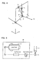
- Fig. 4 shows a kinematic model illustrative of a structure of the coordinate measuring machine 1.
- T1, T2, T3 and T4 denote a fulcrum on X-axis, a fulcrum on Y-axis, a fulcrum on Z-axis and a master ball center point, respectively.
- A, B and P denote a probe tip, a spindle tip and a probe vector headed from the spindle tip B toward the probe tip A.
- TF2, TF3 and TF4 denote vectors headed toward the probe tip A from a measurement point on X-axis, a measurement point on Y-axis, a measurement point on Z-axis and the master ball center point, respectively.
- the geometrical errors to be measured include parallel errors (ex, ey, ez) and rotational errors (#epsilon#x, #epsilon#y, #epsilon#z) at a specific focused fulcrum (also serving as a rotational center) T.
- TFx, TFy, TFz denote vectors headed from fulcrums toward the probe tip
- compensation parameters #delta#x, #delta#y, #delta#z
- the laser interference measuring instrument 30 includes a laser head 31 configured to emit a laser light. It also includes a receiver 32 configured to pass the laser light emitted from the laser head 31 toward the optical tool 21 and receive an incident laser light from the optical tool 21. It further includes an interferometer 33 configured to yield interference fringes when the laser light emitted from the laser head 31 interferes with the laser light reflected from the optical tool 21.
- the interferometer 33 When the optical tool 21 is moved along scales of XYZ, the interferometer 33 yields interference fringes at each position, which are employed to detect parallel errors and rotational errors at the probe position. Measurement of parallel errors and rotational errors throughout the three-dimensional measuring space allows computation of compensation parameters throughout the three-dimensional measuring space.
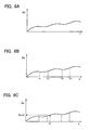
- a compensation parameter #delta#x along the X-axis direction is described for simplification of description.
- a compensation parameter #delta#x corresponding to an X-axis counter value x is computed.
- a compensation parameter #delta#x corresponding to an X-axis counter value x is computed.
- a resultant raw data curve, the number of zone division derived from the shape and a divided position, an interpolating function coefficient in each zone is determined.
- a compensation parameter ⁇ x (X) relative to the counter value x is computed using the interpolating function obtained above. This operation is similarly applied to other compensation parameters on Y-axis and Z-axis. Thus, the amount of data to be stored can be greatly reduced.
- the weight W of the work 19 mounted on the base 12 is switched among 0, 5 ton, 10 ton, ... to measure the geometrical errors in the respective cases as described above and compute compensation parameters for spatial error correction.
- Deformation of the base 12 due to the work weight imparts the greatest influence on a Y-axis angle defined from the base 12 serving as a guide.
- an angular error on Y-axis may be measured using an angle meter, for each work weight.
- Fig. 7 is a flowchart illustrating a flow during actual measurement thus executed in the coordinate measuring machine that stores compensation parameters for each work weight.
- the compensation parameters are stored in the controller 2 as an example.
- the work 19 is mounted on the base 12, and the weight of the work 19 is entered into the host computer 3 (S11).
- the work weight may be entered into the host computer 3 manually by a worker, or may be detected automatically by a weight counter 1a integrated in the base 12, and be sent to the host computer 3.
- Information about the work weight may also be entered directly into the host computer 3 using the input device 3b.
- the host computer 3 sends a work identification code corresponding to the work weight to the controller 2 (S12).
- the controller 2 switches the compensation parameter for use in measurement to a compensation parameter corresponding to the work identification code, among the compensation parameters stored internally (S13). In an actual measurement, the switched compensation parameter is employed to correct a measured value (S14).
- Fig. 8 is a flowchart illustrating a flow in another embodiment of actual measurement executed in the coordinate measuring machine that stores compensation parameters per a weight of a work.
- the compensation parameters are stored in the host computer 3.
- the work 19 is mounted on the base 12, and the weight of the work 19 is entered into the host computer 3 (S21).
- the work weight may be entered into the host computer 3 manually by a worker or through automatic detection by a weight counter integrated in the base 12.
- the host computer 3 sends a compensation parameter corresponding to the work weight to the controller 2 (S22).
- the controller 2 stores the received compensation parameter in an internal memory (S23).
- the stored compensation parameter is employed to correct a measured value (S24).
- the coordinate measuring machine is implemented as a conventional three-dimensional coordinate measuring machine by way of non-limiting example. Rather, it may be implemented in general surface condition measuring machines such as a surface roughness measuring machine, a surface profile measuring machine and a roundness measuring machine.
- the weight counter is exemplified as integrated in the base 12 for automatic detection and entering.
- the weight counter may be integrated in the vibration isolating stand 11.
- a strain gauge of the weight counter may be integrated in the base 12 or the vibration isolating stand 11 to automatically detect a weight based on the amount of strain caused on the base 12 or the vibration isolating stand 11.
- the weight counter may measure a tilt at a portion in the measuring machine such as the base 12 or the beam support 13a, 13b and automatically detect a weight based on the amount of tilt.
- the compensation parameter corresponding to the weight of the work to be measured is employed to correct the measured coordinates of the work. Therefore, it is possible to relief the restriction on the work weight in the coordinate measuring machine and to improve the work measurement precision as well. Accordingly, it is possible to improve the availability of the measuring machine and result in an improved economic efficiency.
Landscapes
- Physics & Mathematics (AREA)
- General Physics & Mathematics (AREA)
- Length Measuring Devices With Unspecified Measuring Means (AREA)
Applications Claiming Priority (2)
| Application Number | Priority Date | Filing Date | Title |
|---|---|---|---|
| JP2004025942 | 2004-02-02 | ||
| JP2004025942A JP4675047B2 (ja) | 2004-02-02 | 2004-02-02 | 三次元測定機の測定座標補正方法及び三次元測定システム |
Publications (2)
| Publication Number | Publication Date |
|---|---|
| EP1559990A2 true EP1559990A2 (fr) | 2005-08-03 |
| EP1559990A3 EP1559990A3 (fr) | 2007-12-12 |
Family
ID=34650895
Family Applications (1)
| Application Number | Title | Priority Date | Filing Date |
|---|---|---|---|
| EP05001487A Withdrawn EP1559990A3 (fr) | 2004-02-02 | 2005-01-25 | Système de mesure de coordonnées et methode pour corriger les coordonnées mesurées avec un appareil de mesure de coordonnées |
Country Status (4)
| Country | Link |
|---|---|
| US (1) | US7171320B2 (fr) |
| EP (1) | EP1559990A3 (fr) |
| JP (1) | JP4675047B2 (fr) |
| CN (1) | CN1651858A (fr) |
Cited By (19)
| Publication number | Priority date | Publication date | Assignee | Title |
|---|---|---|---|---|
| WO2009013768A1 (fr) * | 2007-07-24 | 2009-01-29 | Hexagon Metrology S.P.A. | Procédé de compensation d'erreurs de mesure d'une machine de mesure provenant des déformations du banc de machine provoquées par la charge exercée par l'unité mobile de la machine sur le banc de machine, et machine de mesure fonctionnant selon ledit procédé |
| WO2009013769A1 (fr) * | 2007-07-24 | 2009-01-29 | Hexagon Metrology S.P.A. | Procédé permettant de compenser les erreurs de mesure provoquées par des déformations d'un banc de machine sous le poids d'une pièce usinée et machine de mesure fonctionnant selon ledit procédé |
| EP2219010A1 (fr) | 2009-02-11 | 2010-08-18 | Leica Geosystems AG | Machine de mesure de coordonnées (CMM) et procédé de compensation d'erreurs dans une CMM |
| WO2011000954A1 (fr) | 2009-07-03 | 2011-01-06 | Leica Geosystems Ag | Machine de mesure des coordonnées (cmm) et procédé de compensation d'erreurs dans une cmm |
| CN102538728A (zh) * | 2011-12-27 | 2012-07-04 | 中国重汽集团杭州发动机有限公司 | 三坐标智能测量方法 |
| EP2505956A1 (fr) | 2011-03-29 | 2012-10-03 | Hexagon Technology Center GmbH | Machine de mesure de coordonnées |
| EP2557390A1 (fr) * | 2011-08-12 | 2013-02-13 | Hexagon Metrology S.p.A. | Machine de mesure fournie avec un bloc de béton ayant la fonction de fondation ou banc de fraiseuse et procédé de compensation des erreurs de mesure dues aux déformations du bloc |
| EP2615409A1 (fr) * | 2012-01-13 | 2013-07-17 | Mitutoyo Corporation | Procédé de correction de coordonnées de mesure, produit de programme d'ordinateur et dispositif de mesure de coordonnées |
| EP2762831A1 (fr) | 2013-02-05 | 2014-08-06 | Hexagon Technology Center GmbH | Surveillance dynamique d'une machine de mesure de coordonnées à l'aide d'un filtrage récursif |
| EP2762830A1 (fr) | 2013-02-05 | 2014-08-06 | Hexagon Technology Center GmbH | Modélisation et surveillance dynamique d'une machine de mesure de coordonnées |
| EP2762829A1 (fr) | 2013-02-05 | 2014-08-06 | Hexagon Technology Center GmbH | Modélisation variable d'un dispositif de mesure |
| EP2998696A1 (fr) | 2014-09-18 | 2016-03-23 | Hexagon Technology Center GmbH | Procédé pour compenser un comportement avec dépendence directionelle d'une sonde tactile CMM |
| EP3034991A1 (fr) | 2014-12-19 | 2016-06-22 | Hexagon Technology Center GmbH | Procédé de compensation active des forces de déplacement avec une unité de sonde |
| WO2016173625A1 (fr) | 2015-04-28 | 2016-11-03 | Hexagon Technology Center Gmbh | Amortissement actif de dispositif de mesure |
| DE102015116853A1 (de) * | 2015-10-05 | 2017-04-06 | Carl Zeiss Industrielle Messtechnik Gmbh | Computerimplementiertes Verfahren und Verfahren zum Betreiben eines Koordinatenmessgeräts |
| DE102015219141A1 (de) * | 2015-10-02 | 2017-04-06 | Deckel Maho Seebach Gmbh | Verfahren und Vorrichtung zur Vermessung einer numerisch gesteuerten Werkzeugmaschine |
| WO2017080612A1 (fr) | 2015-11-13 | 2017-05-18 | Hexagon Technology Center Gmbh | Compensation d'erreur pour machines de mesure de coordonnées au moyen d'un module de référence |
| EP3470777A1 (fr) | 2017-10-10 | 2019-04-17 | Hexagon Technology Center GmbH | Système pour déterminer l'état d'une machine de positionnement d'outils |
| EP3667443A1 (fr) * | 2018-12-14 | 2020-06-17 | Agie Charmilles SA | Procédé de correction de mouvements d'axe |
Families Citing this family (23)
| Publication number | Priority date | Publication date | Assignee | Title |
|---|---|---|---|---|
| JP4464318B2 (ja) * | 2005-05-16 | 2010-05-19 | オークマ株式会社 | パラレルメカニズム機械のキャリブレーション方法 |
| DE102006015725A1 (de) * | 2006-04-04 | 2007-10-11 | Dr. Johannes Heidenhain Gmbh | Verfahren zum Initialisieren eines Positionsmesssystems |
| DE102007011852A1 (de) * | 2007-03-03 | 2008-09-04 | Afm Technology Gmbh | Verfahren und Vorrichtung zur Korrektur eines Positionierungssystems |
| ITTO20070318A1 (it) * | 2007-05-10 | 2008-11-11 | Hexagon Metrology Spa | Metodo per la determinazione degli errori geometrici in una macchina utensile o di misura |
| JP5297818B2 (ja) * | 2009-01-06 | 2013-09-25 | 株式会社ミツトヨ | 三次元測定機 |
| KR101255479B1 (ko) * | 2010-01-19 | 2013-04-16 | 경북대학교 산학협력단 | 다축 제어 기계의 직선축과 회전축 간의 기하학적 오차 평가 방법 |
| KR101126808B1 (ko) * | 2010-03-02 | 2012-03-23 | 경북대학교 산학협력단 | 다축 제어 기계의 오차 평가 방법 및 장치 |
| JP5509013B2 (ja) * | 2010-09-17 | 2014-06-04 | 株式会社ミツトヨ | 三次元測定機の測定データ補正方法および三次元測定機 |
| DE102010052503B4 (de) * | 2010-11-26 | 2012-06-21 | Wenzel Scantec Gmbh | Verfahren zur Steuerung eines Koordinatenmessgeräts sowie Koordinatenmessgerät |
| US9182221B2 (en) | 2011-06-13 | 2015-11-10 | Canon Kabushiki Kaisha | Information processing apparatus and information processing method |
| CN103134451A (zh) * | 2011-11-30 | 2013-06-05 | 鸿富锦精密工业(深圳)有限公司 | 三坐标测量机三轴垂直度误差补偿系统及方法 |
| CN102935604A (zh) * | 2012-11-02 | 2013-02-20 | 慈溪市汇丽机电有限公司 | 一种加工工件角度校正方法 |
| DE102013204581A1 (de) | 2013-03-15 | 2014-09-18 | Carl Zeiss Industrielle Messtechnik Gmbh | Verfahren zur Korrektur einer Winkelabweichung beim Betrieb eines Koordinatenmessgeräts |
| CN103395301B (zh) * | 2013-07-17 | 2016-07-06 | 大族激光科技产业集团股份有限公司 | 一种激光打标机三维校正方法和装置 |
| EP2878920A1 (fr) * | 2013-11-28 | 2015-06-03 | Hexagon Technology Center GmbH | Étalonnage d'une machine de mesure de coordonnées à l'aide d'une tête laser d'étalonnage au niveau du point d'outil |
| DE102014209342A1 (de) | 2014-05-16 | 2015-11-19 | Carl Zeiss Microscopy Gmbh | Verfahren zur Ermittlung von Geometriedaten eines Objektes mit einem Messmikroskop und Messmikroskop |
| CN105043314B (zh) * | 2015-04-30 | 2017-11-21 | 东莞市神州视觉科技有限公司 | 一种用于锡膏检测精度检验的棱台参数测量方法和系统 |
| JP6295299B2 (ja) * | 2016-08-26 | 2018-03-14 | 株式会社ミツトヨ | 座標補正方法及び三次元測定装置 |
| KR102217446B1 (ko) * | 2017-06-30 | 2021-02-22 | 주식회사 엘지화학 | 이차전지용 전극의 두께 측정장치 |
| CN107576265B (zh) * | 2017-08-07 | 2019-11-12 | 北京理工大学 | 一种激光干涉仪自动对光的测量方法 |
| JP6942577B2 (ja) | 2017-09-15 | 2021-09-29 | オークマ株式会社 | 工作機械の数値制御装置及び数値制御方法 |
| CN108801193B (zh) * | 2018-08-28 | 2020-05-05 | 大连民族大学 | 一种基于误差与变异规律的三坐标测量机误差测量方法 |
| CN112595341B (zh) * | 2020-11-11 | 2022-04-22 | 北京航天时代激光导航技术有限责任公司 | 一种六面体工装底板高精度安装调校方法 |
Family Cites Families (12)
| Publication number | Priority date | Publication date | Assignee | Title |
|---|---|---|---|---|
| JPH04372342A (ja) * | 1991-06-17 | 1992-12-25 | Toyota Motor Corp | 定盤歪み補正装置及び定盤歪み補正方法 |
| JP2870720B2 (ja) * | 1993-03-25 | 1999-03-17 | 日立機電工業株式会社 | 円柱状物体の直径測定方法 |
| NO302055B1 (no) * | 1993-05-24 | 1998-01-12 | Metronor As | Fremgangsmåte og system for geometrimåling |
| JP2902285B2 (ja) | 1993-11-22 | 1999-06-07 | 株式会社ミツトヨ | 三次元位置制御システム |
| DE4342312A1 (de) * | 1993-12-11 | 1995-06-14 | Zeiss Carl Fa | Verfahren zur Korrektur von schwingungsbedingten Meßfehlern bei Koordinatenmeßgeräten |
| JPH08229774A (ja) | 1995-03-02 | 1996-09-10 | Toshiba Mach Co Ltd | 工作機械の変形補正加工法 |
| JPH10339785A (ja) * | 1997-06-06 | 1998-12-22 | Kuroda Precision Ind Ltd | 摺動体の支持装置 |
| JP4261634B2 (ja) * | 1998-05-11 | 2009-04-30 | キヤノン株式会社 | ステージ装置、露光装置ならびにデバイス製造方法 |
| JP2983941B2 (ja) * | 1997-11-11 | 1999-11-29 | 川崎重工業株式会社 | 3次元自動計測装置用計測誤差補正方法 |
| DE10006876C1 (de) * | 2000-02-16 | 2001-06-13 | Brown & Sharpe Gmbh | Verfahren zur Erhöhung der Genauigkeit und Sicherheit eines Koordinatenmessgerätes |
| JP3634275B2 (ja) * | 2001-03-05 | 2005-03-30 | 株式会社ミツトヨ | 位置測定装置 |
| DE10214489A1 (de) * | 2002-03-26 | 2003-10-23 | Zeiss Carl | Verfahren zur Bestimmung und Korrektur von Führungsfehlern bei einem Koordinatenmeßgerät |
-
2004
- 2004-02-02 JP JP2004025942A patent/JP4675047B2/ja not_active Expired - Fee Related
-
2005
- 2005-01-25 EP EP05001487A patent/EP1559990A3/fr not_active Withdrawn
- 2005-01-31 US US11/046,978 patent/US7171320B2/en not_active Expired - Lifetime
- 2005-02-01 CN CN200510006444.7A patent/CN1651858A/zh active Pending
Cited By (48)
| Publication number | Priority date | Publication date | Assignee | Title |
|---|---|---|---|---|
| WO2009013768A1 (fr) * | 2007-07-24 | 2009-01-29 | Hexagon Metrology S.P.A. | Procédé de compensation d'erreurs de mesure d'une machine de mesure provenant des déformations du banc de machine provoquées par la charge exercée par l'unité mobile de la machine sur le banc de machine, et machine de mesure fonctionnant selon ledit procédé |
| WO2009013769A1 (fr) * | 2007-07-24 | 2009-01-29 | Hexagon Metrology S.P.A. | Procédé permettant de compenser les erreurs de mesure provoquées par des déformations d'un banc de machine sous le poids d'une pièce usinée et machine de mesure fonctionnant selon ledit procédé |
| US8868367B2 (en) | 2007-07-24 | 2014-10-21 | Hexagon Metrology S.P.A | Method of compensating measurement errors of a measuring machine deriving from the deformations of the machine bed caused by the load exerted by the mobile unit of the machine on the machine bed, and measuring machine operating according to said method |
| US9212888B2 (en) | 2007-07-24 | 2015-12-15 | Hexagon Metrology S.P.A. | Method for compensating measurement errors caused by deformations of a measuring machine bed under the load of a workpiece and measuring machine operating according to said method |
| CN101802548B (zh) * | 2007-07-24 | 2012-09-05 | 海克斯康测量技术有限公司 | 补偿测量机器的测量误差的方法和使用该方法的测量机器 |
| EP2219010A1 (fr) | 2009-02-11 | 2010-08-18 | Leica Geosystems AG | Machine de mesure de coordonnées (CMM) et procédé de compensation d'erreurs dans une CMM |
| WO2010092131A1 (fr) | 2009-02-11 | 2010-08-19 | Leica Geosystems Ag | Machine de mesure à coordonnées (cmm) et procédé de compensation des erreurs d'une cmm |
| US9435645B2 (en) | 2009-02-11 | 2016-09-06 | Leica Geosystems Ag | Coordinate measuring machine (CMM) and method of compensating errors in a CMM |
| WO2011000954A1 (fr) | 2009-07-03 | 2011-01-06 | Leica Geosystems Ag | Machine de mesure des coordonnées (cmm) et procédé de compensation d'erreurs dans une cmm |
| US8537372B2 (en) | 2009-07-03 | 2013-09-17 | Leica Geosystems Ag | Coordinate measuring machine (CMM) and method of compensating errors in a CMM |
| US8607466B2 (en) | 2009-07-03 | 2013-12-17 | Leica Geosystems Ag | Coordinate measuring machine (CMM) and method of compensating errors in a CMM |
| WO2011000955A1 (fr) | 2009-07-03 | 2011-01-06 | Leica Geosystems Ag | Machine de mesure des coordonnées (cmm) et procédé de compensation d'erreurs dans une cmm |
| WO2012130832A1 (fr) | 2011-03-29 | 2012-10-04 | Hexagon Technology Center Gmbh | Machine de mesure de coordonnées |
| EP2505956A1 (fr) | 2011-03-29 | 2012-10-03 | Hexagon Technology Center GmbH | Machine de mesure de coordonnées |
| US9086262B2 (en) | 2011-03-29 | 2015-07-21 | Hexagon Technology Center Gmbh | Coordinate measuring machine |
| EP2557390A1 (fr) * | 2011-08-12 | 2013-02-13 | Hexagon Metrology S.p.A. | Machine de mesure fournie avec un bloc de béton ayant la fonction de fondation ou banc de fraiseuse et procédé de compensation des erreurs de mesure dues aux déformations du bloc |
| CN102954776A (zh) * | 2011-08-12 | 2013-03-06 | 海克斯康测量技术有限公司 | 具有用作底座或机座的混凝土块的测量机,以及补偿由该块的变形产生的测量误差的方法 |
| US8844150B2 (en) | 2011-08-12 | 2014-09-30 | Hexagon Metrology S.P.A. | Measuring machine provided with a block of concrete having the function of foundation or machine bed, and method for compensating the measuring errors due to deformations of the block |
| CN102538728A (zh) * | 2011-12-27 | 2012-07-04 | 中国重汽集团杭州发动机有限公司 | 三坐标智能测量方法 |
| EP2615409A1 (fr) * | 2012-01-13 | 2013-07-17 | Mitutoyo Corporation | Procédé de correction de coordonnées de mesure, produit de programme d'ordinateur et dispositif de mesure de coordonnées |
| EP2762830A1 (fr) | 2013-02-05 | 2014-08-06 | Hexagon Technology Center GmbH | Modélisation et surveillance dynamique d'une machine de mesure de coordonnées |
| EP2762831A1 (fr) | 2013-02-05 | 2014-08-06 | Hexagon Technology Center GmbH | Surveillance dynamique d'une machine de mesure de coordonnées à l'aide d'un filtrage récursif |
| EP2762829A1 (fr) | 2013-02-05 | 2014-08-06 | Hexagon Technology Center GmbH | Modélisation variable d'un dispositif de mesure |
| US9593927B2 (en) | 2013-02-05 | 2017-03-14 | Hexagon Technology Center Gmbh | Dynamical monitoring and modelling of a coordinate measuring machine |
| US9593928B2 (en) | 2013-02-05 | 2017-03-14 | Hexagon Technology Center Gmbh | Dynamical monitoring of a coordinate measuring machine using recursive filtering |
| US9797700B2 (en) | 2013-02-05 | 2017-10-24 | Hexagon Technology Center Gmbh | Variable modelling of a measuring device |
| EP2998696A1 (fr) | 2014-09-18 | 2016-03-23 | Hexagon Technology Center GmbH | Procédé pour compenser un comportement avec dépendence directionelle d'une sonde tactile CMM |
| US9733056B2 (en) | 2014-09-18 | 2017-08-15 | Hexagon Technology Center Gmbh | Method for compensating lobing behavior of a CMM touch probe |
| US9726482B2 (en) | 2014-12-19 | 2017-08-08 | Hexagon Technology Center Gmbh | Method of actively counteracting displacement forces with a probing unit |
| EP3034991A1 (fr) | 2014-12-19 | 2016-06-22 | Hexagon Technology Center GmbH | Procédé de compensation active des forces de déplacement avec une unité de sonde |
| EP3289310B1 (fr) | 2015-04-28 | 2022-06-15 | Hexagon Technology Center GmbH | Amortissement actif de dispositif de mesure |
| US10969221B2 (en) | 2015-04-28 | 2021-04-06 | Hexagon Technology Center Gmbh | Active damping of a measuring device |
| EP4080162A1 (fr) | 2015-04-28 | 2022-10-26 | Hexagon Technology Center GmbH | Amortissement actif d'un dispositif de mesure |
| EP4060283A1 (fr) | 2015-04-28 | 2022-09-21 | Hexagon Technology Center GmbH | Amortissement actif d'un dispositif de mesure |
| WO2016173625A1 (fr) | 2015-04-28 | 2016-11-03 | Hexagon Technology Center Gmbh | Amortissement actif de dispositif de mesure |
| US10620003B2 (en) | 2015-04-28 | 2020-04-14 | Hexagon Technology Center Gmbh | Active damping of a measuring device |
| DE102015219141A1 (de) * | 2015-10-02 | 2017-04-06 | Deckel Maho Seebach Gmbh | Verfahren und Vorrichtung zur Vermessung einer numerisch gesteuerten Werkzeugmaschine |
| DE102015219141B4 (de) * | 2015-10-02 | 2025-05-28 | Deckel Maho Seebach Gmbh | Verfahren und vorrichtung zur vermessung einer numerisch gesteuerten werkzeugmaschine, steuerungsvorrichtung, numerisch gesteuerte werkzeugmaschine und computerprogrammprodukt |
| DE102015116853A1 (de) * | 2015-10-05 | 2017-04-06 | Carl Zeiss Industrielle Messtechnik Gmbh | Computerimplementiertes Verfahren und Verfahren zum Betreiben eines Koordinatenmessgeräts |
| WO2017080612A1 (fr) | 2015-11-13 | 2017-05-18 | Hexagon Technology Center Gmbh | Compensation d'erreur pour machines de mesure de coordonnées au moyen d'un module de référence |
| US11073382B2 (en) | 2015-11-13 | 2021-07-27 | Hexagon Technology Center Gmbh | Error compensation for coordinate measuring machines using a reference module |
| US10942020B2 (en) | 2017-10-10 | 2021-03-09 | Hexagon Technology Center Gmbh | System for determining a state of a tool positioning machine |
| EP3470777A1 (fr) | 2017-10-10 | 2019-04-17 | Hexagon Technology Center GmbH | Système pour déterminer l'état d'une machine de positionnement d'outils |
| EP3667443A1 (fr) * | 2018-12-14 | 2020-06-17 | Agie Charmilles SA | Procédé de correction de mouvements d'axe |
| CN111318802A (zh) * | 2018-12-14 | 2020-06-23 | 阿杰·查米莱斯股份有限公司 | 轴运动校正的方法 |
| TWI772717B (zh) * | 2018-12-14 | 2022-08-01 | 瑞士商阿奇夏米爾公司 | 定位機、用於機械校正定位機之軸導引部件的安裝表面之裝置、和用於定位機的幾何運動誤差之機械校正的方法 |
| US11400597B2 (en) | 2018-12-14 | 2022-08-02 | Agie Charmilles Sa | Methods for the correction of axis motions |
| CN111318802B (zh) * | 2018-12-14 | 2023-09-29 | 阿杰·查米莱斯股份有限公司 | 轴运动校正的方法 |
Also Published As
| Publication number | Publication date |
|---|---|
| US20050166412A1 (en) | 2005-08-04 |
| CN1651858A (zh) | 2005-08-10 |
| US7171320B2 (en) | 2007-01-30 |
| EP1559990A3 (fr) | 2007-12-12 |
| JP4675047B2 (ja) | 2011-04-20 |
| JP2005214943A (ja) | 2005-08-11 |
Similar Documents
| Publication | Publication Date | Title |
|---|---|---|
| EP1559990A2 (fr) | Système de mesure de coordonnées et methode pour corriger les coordonnées mesurées avec un appareil de mesure de coordonnées | |
| US8825427B2 (en) | Method for calibrating a coordinate measuring machine | |
| EP2449341B1 (fr) | Machine de mesure de coordonnées (CMM) et procédé de compensation d'erreurs dans une CMM | |
| EP1579168B1 (fr) | Procede d'examen d'une piece et dispositif | |
| US8290733B2 (en) | Modular calibration | |
| US6591208B2 (en) | Correction method for a coordinate measuring apparatus | |
| US7254506B2 (en) | Method of calibrating a scanning system | |
| EP0858015B1 (fr) | Méthode et dispositif de mesure avec sonde à declenchement | |
| EP1818647B1 (fr) | Instrument, procédé et programme de mesure de forme | |
| US8676527B2 (en) | Industrial machine | |
| US6701267B2 (en) | Method for calibrating probe and computer-readable medium | |
| WO2000014474A1 (fr) | Machine de mesure des coordonnees comprenant un bati de machine-outil | |
| US7526873B2 (en) | Use of surface measurement probes | |
| US9310177B2 (en) | Method of correcting measurement data of a coordinate measuring machine and a coordinate measuring machine | |
| WO1998019824A1 (fr) | Appareil de correction d'erreurs pour machine-outil a commande numerique | |
| JP3820357B2 (ja) | 計測方法および計測装置 | |
| JP2005114549A (ja) | 表面形状測定装置および表面形状測定方法 | |
| CN120936458A (zh) | 机床的热位移修正方法以及热位移修正系统 |
Legal Events
| Date | Code | Title | Description |
|---|---|---|---|
| PUAI | Public reference made under article 153(3) epc to a published international application that has entered the european phase |
Free format text: ORIGINAL CODE: 0009012 |
|
| AK | Designated contracting states |
Kind code of ref document: A2 Designated state(s): AT BE BG CH CY CZ DE DK EE ES FI FR GB GR HU IE IS IT LI LT LU MC NL PL PT RO SE SI SK TR |
|
| AX | Request for extension of the european patent |
Extension state: AL BA HR LV MK YU |
|
| PUAL | Search report despatched |
Free format text: ORIGINAL CODE: 0009013 |
|
| AK | Designated contracting states |
Kind code of ref document: A3 Designated state(s): AT BE BG CH CY CZ DE DK EE ES FI FR GB GR HU IE IS IT LI LT LU MC NL PL PT RO SE SI SK TR |
|
| AX | Request for extension of the european patent |
Extension state: AL BA HR LV MK YU |
|
| AKX | Designation fees paid | ||
| STAA | Information on the status of an ep patent application or granted ep patent |
Free format text: STATUS: THE APPLICATION IS DEEMED TO BE WITHDRAWN |
|
| 18D | Application deemed to be withdrawn |
Effective date: 20080613 |
|
| REG | Reference to a national code |
Ref country code: DE Ref legal event code: 8566 |