EP1559992A1 - Vorrichtung zur Erleichterung der Einstellung eines von der Dicke einer Produktbahn abhängigen Systems - Google Patents
Vorrichtung zur Erleichterung der Einstellung eines von der Dicke einer Produktbahn abhängigen Systems Download PDFInfo
- Publication number
- EP1559992A1 EP1559992A1 EP05001178A EP05001178A EP1559992A1 EP 1559992 A1 EP1559992 A1 EP 1559992A1 EP 05001178 A EP05001178 A EP 05001178A EP 05001178 A EP05001178 A EP 05001178A EP 1559992 A1 EP1559992 A1 EP 1559992A1
- Authority
- EP
- European Patent Office
- Prior art keywords
- thickness
- actuator
- web
- product web
- lever
- Prior art date
- Legal status (The legal status is an assumption and is not a legal conclusion. Google has not performed a legal analysis and makes no representation as to the accuracy of the status listed.)
- Withdrawn
Links
- 230000001419 dependent effect Effects 0.000 title claims description 9
- 238000005259 measurement Methods 0.000 claims abstract description 14
- 230000035515 penetration Effects 0.000 abstract 1
- 230000008878 coupling Effects 0.000 description 2
- 238000010168 coupling process Methods 0.000 description 2
- 238000005859 coupling reaction Methods 0.000 description 2
- 230000000694 effects Effects 0.000 description 1
- 230000001747 exhibiting effect Effects 0.000 description 1
- 238000009434 installation Methods 0.000 description 1
Images


Classifications
-
- G—PHYSICS
- G01—MEASURING; TESTING
- G01B—MEASURING LENGTH, THICKNESS OR SIMILAR LINEAR DIMENSIONS; MEASURING ANGLES; MEASURING AREAS; MEASURING IRREGULARITIES OF SURFACES OR CONTOURS
- G01B11/00—Measuring arrangements characterised by the use of optical techniques
- G01B11/02—Measuring arrangements characterised by the use of optical techniques for measuring length, width or thickness
- G01B11/06—Measuring arrangements characterised by the use of optical techniques for measuring length, width or thickness for measuring thickness ; e.g. of sheet material
- G01B11/0691—Measuring arrangements characterised by the use of optical techniques for measuring length, width or thickness for measuring thickness ; e.g. of sheet material of objects while moving
-
- B—PERFORMING OPERATIONS; TRANSPORTING
- B65—CONVEYING; PACKING; STORING; HANDLING THIN OR FILAMENTARY MATERIAL
- B65H—HANDLING THIN OR FILAMENTARY MATERIAL, e.g. SHEETS, WEBS, CABLES
- B65H35/00—Delivering articles from cutting or line-perforating machines; Article or web delivery apparatus incorporating cutting or line-perforating devices, e.g. adhesive tape dispensers
- B65H35/02—Delivering articles from cutting or line-perforating machines; Article or web delivery apparatus incorporating cutting or line-perforating devices, e.g. adhesive tape dispensers from or with longitudinal slitters or perforators
-
- B—PERFORMING OPERATIONS; TRANSPORTING
- B65—CONVEYING; PACKING; STORING; HANDLING THIN OR FILAMENTARY MATERIAL
- B65H—HANDLING THIN OR FILAMENTARY MATERIAL, e.g. SHEETS, WEBS, CABLES
- B65H35/00—Delivering articles from cutting or line-perforating machines; Article or web delivery apparatus incorporating cutting or line-perforating devices, e.g. adhesive tape dispensers
- B65H35/04—Delivering articles from cutting or line-perforating machines; Article or web delivery apparatus incorporating cutting or line-perforating devices, e.g. adhesive tape dispensers from or with transverse cutters or perforators
- B65H35/08—Delivering articles from cutting or line-perforating machines; Article or web delivery apparatus incorporating cutting or line-perforating devices, e.g. adhesive tape dispensers from or with transverse cutters or perforators from or with revolving, e.g. cylinder, cutters or perforators
-
- B—PERFORMING OPERATIONS; TRANSPORTING
- B65—CONVEYING; PACKING; STORING; HANDLING THIN OR FILAMENTARY MATERIAL
- B65H—HANDLING THIN OR FILAMENTARY MATERIAL, e.g. SHEETS, WEBS, CABLES
- B65H2511/00—Dimensions; Position; Numbers; Identification; Occurrences
- B65H2511/10—Size; Dimensions
- B65H2511/13—Thickness
-
- B—PERFORMING OPERATIONS; TRANSPORTING
- B65—CONVEYING; PACKING; STORING; HANDLING THIN OR FILAMENTARY MATERIAL
- B65H—HANDLING THIN OR FILAMENTARY MATERIAL, e.g. SHEETS, WEBS, CABLES
- B65H2511/00—Dimensions; Position; Numbers; Identification; Occurrences
- B65H2511/20—Location in space
- B65H2511/22—Distance
- B65H2511/224—Nip between rollers, between belts or between rollers and belts
-
- B—PERFORMING OPERATIONS; TRANSPORTING
- B65—CONVEYING; PACKING; STORING; HANDLING THIN OR FILAMENTARY MATERIAL
- B65H—HANDLING THIN OR FILAMENTARY MATERIAL, e.g. SHEETS, WEBS, CABLES
- B65H2553/00—Sensing or detecting means
- B65H2553/40—Sensing or detecting means using optical, e.g. photographic, elements
- B65H2553/41—Photoelectric detectors
- B65H2553/414—Photoelectric detectors involving receptor receiving light reflected by a reflecting surface and emitted by a separate emitter
-
- G—PHYSICS
- G01—MEASURING; TESTING
- G01B—MEASURING LENGTH, THICKNESS OR SIMILAR LINEAR DIMENSIONS; MEASURING ANGLES; MEASURING AREAS; MEASURING IRREGULARITIES OF SURFACES OR CONTOURS
- G01B2210/00—Aspects not specifically covered by any group under G01B, e.g. of wheel alignment, caliper-like sensors
- G01B2210/40—Caliper-like sensors
- G01B2210/44—Caliper-like sensors with detectors on both sides of the object to be measured
Definitions
- the invention relates to a device for facilitating the Setting a dependent on the thickness of a product web Systems of a product web processing machine.
- the thickness of the product web is so far with stationary web means determined by hand to the train to be attached measuring device Service.
- the invention is based on the object, a device of of the type mentioned above, with which a contactless, during the web run feasible measurement of the web thickness with subsequent display for manual adjustment or automatic Setting can be performed.
- this is achieved in that on both sides of the Product web each having a transmitter and a receiver exhibiting Measuring head is arranged and the transmitter an oblique to Product web directed, emitted by this reflected beam, depending on the thickness of the product web at different Positions of the receiver impinges and thereby different Measurements generated and the two receivers on the two measured values a measuring signal proportional to the web thickness downstream computer is connected.
- Thickness measurement can, without an operator must approach the product web for measurement, one Thickness measurement done.
- the thickness measurement takes place without contact, so that no effects on the product web through the measurement takes place.
- the measurement can be both at stopped as well as while the product line is running.
- the two transmitters of the measuring heads are on one Track thickness adjusted from zero.
- the measuring heads are on designed a measuring range, which is a flutter of the product web allows.
- the product web does not have to be in a measurement located exactly in the middle between the two measuring heads, so that the Device also on an easily accessible, longer free-running Section of the product web can be arranged.
- the Measuring signal for controlling an actuator for at least one web thickness dependent system of the processing machine used It is therefore not just one without the use of one Operator to be performed thickness measurement possible, with whose control value then corresponding systems Machine tool can be adjusted by hand, but also a fully automatic adjustment of these systems.
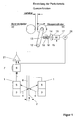
- the apparatus of Figure 1 has two designated overall by 1 Measuring heads, which are equally spaced on both sides of the ideal Running level of a product web 2 are arranged. It can the Product web 2 consist of several layers.
- Each measuring head 1 has a transmitter 3.
- Each transmitter 3 sends an oblique to Product web 2 directed, focused beam 4. Every ray 4 is reflected on the product web 2.
- the reflected part hits a receiver 5 of each measuring head 1.
- the two transmitters 3 of Measuring heads 1 adjusted to a sheet thickness of zero after installation become.
- the reception range of the receiver 5 is so designed so that the reflected rays 4 still detected when the product web 2 within a through the boundary lines 8 indicated measuring range 9 flutters.
- the measured values the two receivers 5 are then guided to a computer 6, which generates a measurement signal from the two measured values.
- This Measuring signal can in the simplest case to a display instrument. 7 from which it is read and then to the setting one or more of the web thickness dependent systems of Processing machine is used.
- FIG. 1 shows a system for setting the perforation depth of a Perforating system in a folding unit of a web-fed rotary printing machine with a fixedly mounted groove cylinder 10 and an adjustable Perforiermesserzylinder 11.
- This cylinder is rotatable in a pivotable about a stationary pin 12 Lever 13 stored.
- On the lever 13 is the one end of a control shaft fourteenth hinged, the other end via a coupling 15 with a Shaft 16 of an actuator 17 is connected.
- the coupling 15 allows axial movements of the actuating shaft 14 relative to shaft 16.
- the actuator 17 is optionally an electric motor with a Reduction gear formed.
- With the control shaft 14 is a Threaded spindle 18 firmly connected, which in a stationary Threaded bearing 19 engages. A rotation of the shafts 14, 16 calls Therefore, a pivoting of the lever 13 and thus a setting of the gap between the cylinders 10 and 11.
- FIG. 2 shows the arrangement of a system for braking a Product with a brake cam 25 and a counter-cylinder 26, the both are driven in rotation.
- the actuator 17 via the clutch 15, a threaded spindle 27 driven, in a stationary threaded bearing 28 engages.
- a stop 29 mounted, which with a one-armed lever 30th interacts.
- the lever 30 is a stationary pin 31st rotatable and serves to support the brake cam 25.
- On the lever 30th engages a pneumatic cylinder 32, the lever 30 in elastic Holds the system at stop 29.
- FIG. 3 shows a system for simultaneous adjustment of two between a gap limiting rollers 35, 36th Im Example shown here are the rollers of a A longitudinal folder. In the same way, however, can also Feed rollers are set.
- each of the rollers 35, 36 at one end of a two-armed lever 37, 38 stored.
- everyone who Lever 37, 38 is pivotable about a stationary pin 39, 40 and carries at its other end a threaded bearing 41, 42.
- 42 engages in each case a threaded spindle 43, 44 a.
- the threaded spindles 43, 44 have opposite threads.
- the threaded spindles 43, 44 are in turn on the control shaft 14th attached, via the clutch 15 from the actuator 17th can be driven.
- FIG. 4 shows a system for producing a longitudinal perforation.
- a grooved roll 50 and a perforating roll 51 are each up a one-armed lever 52, 53 mounted. Every lever is around you fixed pin 54, 55 pivotally mounted.
- At the free end of each Levers 52, 53 is in turn each a threaded bearing 56, 57 attached, in each of which a threaded spindle 58, 59 engages.
- the threaded spindles 58, 59 are fixedly arranged on the actuating shaft 14, which over the Clutch 15 can be rotated by the actuator 17 in rotation.
- the invention is not limited to the illustrated embodiments limited, but may also affect the web thickness in others adjustable systems, for example, to adjust the Falzkupplungsspalts be applied.
Landscapes
- Physics & Mathematics (AREA)
- General Physics & Mathematics (AREA)
- Controlling Rewinding, Feeding, Winding, Or Abnormalities Of Webs (AREA)
Abstract
Description
Claims (13)
- Vorrichtung zur Erleichterung der Einstellung eines von der Dicke einer Produktbahn abhängigen Systems einer Produktbahn-Bearbeitungsmaschine, dadurch gekennzeichnet, dass beiderseits der Produktbahn (2) je ein einen Sender (3) und einen Empfänger (5) aufweisender Messkopf (1) angeordnet ist und der Sender (3) einen schräg zur Produktbahn (2) gerichteten, von dieser reflektierten Strahl (4) aussendet, der in Abhängigkeit von der Dicke der Produktbahn (2) an unterschiedlichen Stellen des Empfängers (5) auftrifft und dadurch unterschiedliche Messwerte erzeugt, und den beiden Empfängern (5) ein aus den beiden Messwerten ein der Bahndicke proportionales Messsignal bildender Rechner (6) nachgeschaltet ist.
- Vorrichtung nach Anspruch 1, dadurch gekennzeichnet, dass die beiden Sender (3) der Messköpfe (1) auf eine Bahndicke von Null justiert sind.
- Vorrichtung nach Anspruch 1 oder 2, dadurch gekennzeichnet, dass die Messköpfe (1) auf einen Messbereich (9) ausgelegt sind, der ein Flattern der Produktbahn (2) zulässt.
- Vorrichtung nach einem der vorhergehenden Ansprüche, dadurch gekennzeichnet, dass das Messsignal zur Ansteuerung eines Stellantriebes (17) für mindestens ein von der Bahndicke abhängiges System der Bearbeitungsmaschine verwendet wird.
- Vorrichtung nach Anspruch 4, dadurch gekennzeichnet, dass das von dem Rechner (6) gelieferte Messsignal mit einem durch ein Potentiometer (20) gelieferten, der Stellung des von der Bahndicke abhängigen Systems proportionalen Messwert in einen Komparator (21) verglichen und zu einem Stellwert für einen Stellantrieb (17) verarbeitet wird.
- Vorrichtung nach Anspruch 4 oder 5, dadurch gekennzeichnet, dass der Stellantrieb (17) einen Elektromotor aufweist.
- Vorrichtung nach einem der Ansprüche 4 bis 6, dadurch gekennzeichnet, dass die Welle des Stellantriebs (17) mit dem die Stellbewegung erfassenden Potentiometer (20) verbunden ist und das Potentiometer ein die Stellbewegung bei Erreichen des Wertes des Messsignals beendenden Komparator (21) ansteuert.
- Vorrichtung nach einem der Ansprüche 4 bis 7, gekennzeichnet durch die Anwendung für ein von der Produktbahndicke abhängiges System eines Falzwerkes einer RollenrotationsDruckmaschine.
- Vorrichtung nach einem der Ansprüche 4 bis 8, dadurch gekennzeichnet, dass zur Einstellung der Perforiertiefe eines Querperforiersystems die vom Stellantrieb (17) angetriebene Stellwelle (14) mit einer in einem ortsfesten Gewindelager (19) geführten Gewindespindel (18) mit Schrägverzahnung verbunden ist und die Stellwelle mittig an einem einarmigen Hebel (13) angreift, dessen eines Ende um einen ortsfesten Zapfen (12) schwenkbar gelagert ist und dessen anderes Ende drehbar einen Perforiermesserzylinder (11) trägt, der mit einem ortsfest gelagerten Nutenzylinder (10) zusammenwirkt.
- Vorrichtung nach einem der Ansprüche 4 bis 8, dadurch gekennzeichnet, dass zur gleichzeitigen gegenläufigen Einstellung zweier Zylinder (35, 36, 50, 51) ier Stellwelle (14) mit zwei Gewindespindeln (43, 44, 58, 59) mit gegenläufigen Gewinden versehen ist, jede Gewindespindel in ein ortsfestes Gewindelager (41, 42, 56, 57) eingreift und jedes Gewindelager an einem einen Zylinder (35, 36, 50, 51) tragenden Hebel (37, 38, 52, 53) befestigt ist.
- Vorrichtung nach Anspruch 10, dadurch gekennzeichnet, dass an dem einen Hebel (53) ein Perforiermesserzylinder (51) und an dem anderen Hebel (52) ein Nutenzylinder (50) eines Längsperforiersystems gelagert ist.
- Vorrichtung nach Anspruch 10, dadurch gekennzeichnet, dass zur Bildung eines Längsfalzsystems je ein Falzzylinder (35, 36) an einem Hebel (37, 38) gelagert ist.
- Vorrichtung nach Anspruch 10, dadurch gekennzeichnet, dass zur Bildung einer Bahnabbremssystems eine vom Stellantrieb (17) angetriebene Gewindespindel (27) mit einem Anschlag (29) vorgesehen ist und gegen den Anschlag ein eine Bremsnocke (25) tragender Hebel (30) elastisch geführt ist.
Applications Claiming Priority (2)
| Application Number | Priority Date | Filing Date | Title |
|---|---|---|---|
| DE102004004012 | 2004-01-27 | ||
| DE200410004012 DE102004004012A1 (de) | 2004-01-27 | 2004-01-27 | Vorrichtung zur Erleichterung der Einstellung der Dicke einer Produktbahn |
Publications (1)
| Publication Number | Publication Date |
|---|---|
| EP1559992A1 true EP1559992A1 (de) | 2005-08-03 |
Family
ID=34638754
Family Applications (1)
| Application Number | Title | Priority Date | Filing Date |
|---|---|---|---|
| EP05001178A Withdrawn EP1559992A1 (de) | 2004-01-27 | 2005-01-21 | Vorrichtung zur Erleichterung der Einstellung eines von der Dicke einer Produktbahn abhängigen Systems |
Country Status (2)
| Country | Link |
|---|---|
| EP (1) | EP1559992A1 (de) |
| DE (1) | DE102004004012A1 (de) |
Cited By (3)
| Publication number | Priority date | Publication date | Assignee | Title |
|---|---|---|---|---|
| FR2867718A1 (fr) * | 2004-03-17 | 2005-09-23 | Roland Man Druckmasch | Machine a imprimer avec un dispositif pour la mesure d'un produit d'impression |
| WO2009142095A1 (ja) * | 2008-05-22 | 2009-11-26 | 三菱重工業株式会社 | ローラの隙間調整装置及び方法 |
| CN109844446A (zh) * | 2017-01-19 | 2019-06-04 | 惠普发展公司,有限责任合伙企业 | 测量打印介质的厚度 |
Families Citing this family (1)
| Publication number | Priority date | Publication date | Assignee | Title |
|---|---|---|---|---|
| DE102010052482A1 (de) * | 2010-11-26 | 2012-05-31 | Kraussmaffei Berstorff Gmbh | Walzenspaltmesssystem |
Citations (6)
| Publication number | Priority date | Publication date | Assignee | Title |
|---|---|---|---|---|
| US3671726A (en) | 1969-05-23 | 1972-06-20 | Morvue Inc | Electro-optical apparatus for precise on-line measurement of the thickness of moving strip material |
| DE3437449A1 (de) | 1984-10-12 | 1986-04-17 | Betriebsforschungsinstitut VDEh - Institut für angewandte Forschung GmbH, 4000 Düsseldorf | Vorrichtung zur erfassung von dickenschwankungen bei kaltgewalzten blechen |
| US4773760A (en) | 1986-05-14 | 1988-09-27 | Tapio Makkonen | Procedure and means for measuring the thickness of a film-like or sheet-like web |
| EP0428903A2 (de) * | 1989-11-17 | 1991-05-29 | Electronic Systems S.P.A. | Verfahren und Vorrichtung zum Kontrollieren und Regulieren der Positionierung metallischer Verstärkungsdrähte innerhalb Gummibogen, insbesondere für die Reifenherstellung |
| US5496407A (en) | 1993-04-19 | 1996-03-05 | Mcaleavey; Michael E. | System and method for monitoring and controlling thickness |
| US5581353A (en) | 1995-02-14 | 1996-12-03 | Qualitek Ltd. | Laser-based measurement apparatus and method for the on-line measurement of multiple corrugated board characteristics |
Family Cites Families (2)
| Publication number | Priority date | Publication date | Assignee | Title |
|---|---|---|---|---|
| DE4220501A1 (de) * | 1992-06-23 | 1994-01-05 | Robert Prof Dr Ing Massen | Optische Dickenmessung an bahnförmigen Materialien |
| DE59604849D1 (de) * | 1995-11-08 | 2000-05-04 | Koenig & Bauer Ag | Falzvorrichtung |
-
2004
- 2004-01-27 DE DE200410004012 patent/DE102004004012A1/de not_active Withdrawn
-
2005
- 2005-01-21 EP EP05001178A patent/EP1559992A1/de not_active Withdrawn
Patent Citations (7)
| Publication number | Priority date | Publication date | Assignee | Title |
|---|---|---|---|---|
| US3671726A (en) | 1969-05-23 | 1972-06-20 | Morvue Inc | Electro-optical apparatus for precise on-line measurement of the thickness of moving strip material |
| US3671726B1 (de) | 1969-05-23 | 1984-02-21 | ||
| DE3437449A1 (de) | 1984-10-12 | 1986-04-17 | Betriebsforschungsinstitut VDEh - Institut für angewandte Forschung GmbH, 4000 Düsseldorf | Vorrichtung zur erfassung von dickenschwankungen bei kaltgewalzten blechen |
| US4773760A (en) | 1986-05-14 | 1988-09-27 | Tapio Makkonen | Procedure and means for measuring the thickness of a film-like or sheet-like web |
| EP0428903A2 (de) * | 1989-11-17 | 1991-05-29 | Electronic Systems S.P.A. | Verfahren und Vorrichtung zum Kontrollieren und Regulieren der Positionierung metallischer Verstärkungsdrähte innerhalb Gummibogen, insbesondere für die Reifenherstellung |
| US5496407A (en) | 1993-04-19 | 1996-03-05 | Mcaleavey; Michael E. | System and method for monitoring and controlling thickness |
| US5581353A (en) | 1995-02-14 | 1996-12-03 | Qualitek Ltd. | Laser-based measurement apparatus and method for the on-line measurement of multiple corrugated board characteristics |
Cited By (4)
| Publication number | Priority date | Publication date | Assignee | Title |
|---|---|---|---|---|
| FR2867718A1 (fr) * | 2004-03-17 | 2005-09-23 | Roland Man Druckmasch | Machine a imprimer avec un dispositif pour la mesure d'un produit d'impression |
| WO2009142095A1 (ja) * | 2008-05-22 | 2009-11-26 | 三菱重工業株式会社 | ローラの隙間調整装置及び方法 |
| CN109844446A (zh) * | 2017-01-19 | 2019-06-04 | 惠普发展公司,有限责任合伙企业 | 测量打印介质的厚度 |
| CN109844446B (zh) * | 2017-01-19 | 2022-09-30 | 惠普发展公司,有限责任合伙企业 | 打印机系统和用于测量打印介质的厚度的方法 |
Also Published As
| Publication number | Publication date |
|---|---|
| DE102004004012A1 (de) | 2005-08-18 |
Similar Documents
| Publication | Publication Date | Title |
|---|---|---|
| DE2642381C3 (de) | Einrichtung zum registerhaltigen Zuführen einer Bahn | |
| DE4327211B4 (de) | Vorrichtung zum Voreinstellen des Schnittregisters in dem Falzapparat einer Rollendruckmaschine | |
| DE3838314A1 (de) | Falzklappenzylinder fuer eine rollenrotationsdruckmaschine | |
| DE3613969A1 (de) | Ueberwachungsvorrichtung fuer die geschuppte bogenzufuhr zu druckmaschinen | |
| DE102015008375A1 (de) | Vorrichtung zur Herstellung von Druckerzeugnissen | |
| AT508112A4 (de) | Messerführung für eine vorrichtung zur ausgabe von papierabschnitten | |
| EP0859730B1 (de) | Falzvorrichtung | |
| DE10129889A1 (de) | Verfahren und Vorrichtung zur Störungserfassung beim Transport einer Bahn | |
| EP1559992A1 (de) | Vorrichtung zur Erleichterung der Einstellung eines von der Dicke einer Produktbahn abhängigen Systems | |
| DE19949951A1 (de) | Flachmaterial verarbeitende Maschine und Regelverfahren dafür | |
| DE10156206A1 (de) | Vorrichtung und Verfahren zum Messen der Bahnspannung | |
| DE102008035754B4 (de) | Verfahren und Vorrichtung zum Einstellen einer Position von Führungs- und/oder Transportrollen für Bedruckstoffe in Druckmaschinen | |
| EP2974833A1 (de) | Vorrichtung und verfahren zum ermitteln des zustandes der messer an einer faserschneid-vorrichtung | |
| EP3016805A1 (de) | Verfahren und vorrichtung zum gegenseitigen anstellen von zwei zylindern in einer druckmaschine | |
| DE10154506A1 (de) | Vorrichtung und Verfahren zur Bestimmung eines Überlapps einer Signatur | |
| EP3718728B1 (de) | Bahnbeobachtungssystem und verfahren zur bahnbeobachtung | |
| DE4426992A1 (de) | Verfahren und Vorrichtung zur Zustandsüberwachung einer umstellbaren Bogendruckmaschine | |
| EP1740488B1 (de) | Temperaturüberwachung einer laufrolle in einer maschine | |
| DE102007032911A1 (de) | Verfahren zum Betrieb eines Längsfalzapparates | |
| EP2168732A2 (de) | Vorrichtung zur Seitenregistrierung von Teilbahnen | |
| EP1201590B1 (de) | Falzwalzenabstandeinstellung | |
| EP3941747B1 (de) | Verfahren zum bestimmen einer position des gegenseitigen kontaktes zwischen einer druckwalze und mindestens einer gegenwalze einer flexodruckmaschine. | |
| EP2498993B1 (de) | Rotationsdruckmaschine mit zumindest einem farb- oder druckwerk | |
| EP1378475A2 (de) | Zugwale mit verstellbarem zugring | |
| DE2263176A1 (de) | Verfahren und vorrichtung zur spannungssteuerung von rotationspressen |
Legal Events
| Date | Code | Title | Description |
|---|---|---|---|
| PUAI | Public reference made under article 153(3) epc to a published international application that has entered the european phase |
Free format text: ORIGINAL CODE: 0009012 |
|
| AK | Designated contracting states |
Kind code of ref document: A1 Designated state(s): AT BE BG CH CY CZ DE DK EE ES FI FR GB GR HU IE IS IT LI LT LU MC NL PL PT RO SE SI SK TR |
|
| AX | Request for extension of the european patent |
Extension state: AL BA HR LV MK YU |
|
| 17P | Request for examination filed |
Effective date: 20051223 |
|
| AKX | Designation fees paid |
Designated state(s): DE FR GB IT |
|
| RAP1 | Party data changed (applicant data changed or rights of an application transferred) |
Owner name: MANROLAND AG |
|
| 17Q | First examination report despatched |
Effective date: 20101123 |
|
| 19U | Interruption of proceedings before grant |
Effective date: 20120201 |
|
| 19W | Proceedings resumed before grant after interruption of proceedings |
Effective date: 20130201 |
|
| RAP1 | Party data changed (applicant data changed or rights of an application transferred) |
Owner name: MANROLAND WEB SYSTEMS GMBH |
|
| STAA | Information on the status of an ep patent application or granted ep patent |
Free format text: STATUS: THE APPLICATION IS DEEMED TO BE WITHDRAWN |
|
| 18D | Application deemed to be withdrawn |
Effective date: 20150324 |