EP1560042A2 - Capteur de détection de vibrations, en particulier de vibrations sismiques - Google Patents
Capteur de détection de vibrations, en particulier de vibrations sismiques Download PDFInfo
- Publication number
- EP1560042A2 EP1560042A2 EP05100534A EP05100534A EP1560042A2 EP 1560042 A2 EP1560042 A2 EP 1560042A2 EP 05100534 A EP05100534 A EP 05100534A EP 05100534 A EP05100534 A EP 05100534A EP 1560042 A2 EP1560042 A2 EP 1560042A2
- Authority
- EP
- European Patent Office
- Prior art keywords
- track
- sensor according
- seat
- approximately
- tracks
- Prior art date
- Legal status (The legal status is an assumption and is not a legal conclusion. Google has not performed a legal analysis and makes no representation as to the accuracy of the status listed.)
- Withdrawn
Links
- 239000004020 conductor Substances 0.000 claims abstract description 17
- 239000000463 material Substances 0.000 claims description 10
- 239000012780 transparent material Substances 0.000 claims description 5
- 238000000034 method Methods 0.000 claims description 4
- 230000008569 process Effects 0.000 claims description 3
- 238000007650 screen-printing Methods 0.000 claims description 3
- XAGFODPZIPBFFR-UHFFFAOYSA-N aluminium Chemical compound [Al] XAGFODPZIPBFFR-UHFFFAOYSA-N 0.000 claims description 2
- 229910052782 aluminium Inorganic materials 0.000 claims description 2
- 239000011810 insulating material Substances 0.000 claims description 2
- 230000000284 resting effect Effects 0.000 claims description 2
- 229940100890 silver compound Drugs 0.000 claims description 2
- 150000003379 silver compounds Chemical class 0.000 claims description 2
- 238000002604 ultrasonography Methods 0.000 claims description 2
- 238000003466 welding Methods 0.000 claims description 2
- 230000001133 acceleration Effects 0.000 description 5
- 230000004044 response Effects 0.000 description 5
- 230000000670 limiting effect Effects 0.000 description 3
- 230000010355 oscillation Effects 0.000 description 3
- 238000000151 deposition Methods 0.000 description 2
- 238000004519 manufacturing process Methods 0.000 description 2
- QSHDDOUJBYECFT-UHFFFAOYSA-N mercury Chemical compound [Hg] QSHDDOUJBYECFT-UHFFFAOYSA-N 0.000 description 2
- 229910052753 mercury Inorganic materials 0.000 description 2
- 230000000630 rising effect Effects 0.000 description 2
- 230000035945 sensitivity Effects 0.000 description 2
- 241000282414 Homo sapiens Species 0.000 description 1
- 208000027418 Wounds and injury Diseases 0.000 description 1
- 239000003795 chemical substances by application Substances 0.000 description 1
- 230000002596 correlated effect Effects 0.000 description 1
- 230000006378 damage Effects 0.000 description 1
- 230000003247 decreasing effect Effects 0.000 description 1
- 238000001514 detection method Methods 0.000 description 1
- 238000009826 distribution Methods 0.000 description 1
- 208000014674 injury Diseases 0.000 description 1
- 238000005304 joining Methods 0.000 description 1
- 230000007246 mechanism Effects 0.000 description 1
- 230000009528 severe injury Effects 0.000 description 1
Images


Classifications
-
- G—PHYSICS
- G01—MEASURING; TESTING
- G01V—GEOPHYSICS; GRAVITATIONAL MEASUREMENTS; DETECTING MASSES OR OBJECTS; TAGS
- G01V1/00—Seismology; Seismic or acoustic prospecting or detecting
- G01V1/01—Measuring or predicting earthquakes
-
- G—PHYSICS
- G01—MEASURING; TESTING
- G01V—GEOPHYSICS; GRAVITATIONAL MEASUREMENTS; DETECTING MASSES OR OBJECTS; TAGS
- G01V1/00—Seismology; Seismic or acoustic prospecting or detecting
- G01V1/16—Receiving elements for seismic signals; Arrangements or adaptations of receiving elements
Definitions
- the present invention relates to a sensor for detecting vibrations, particularly seismic waves.
- Earthquakes have always been a factor of extreme danger for human beings, since these phenomena often generate an amount of energy, in the form of undulatory or sussultatory movements of the earth's crust, that is capable of causing extremely severe damage to buildings and injury to people.
- the seismic event has, during its occurrence, an intensity that increases over time until it reaches a peak, subsequently decreasing again.
- Analysis of seismic phenomena is generally conducted with the aid of dedicated scientific means, which are capable of detecting the amplitude of the vibrations generated by a seismic phenomenon.
- seismograph is currently in use in seismological centers distributed almost throughout the world and are constituted by a pen mounted at an end of a thin rod, which during an even minimal oscillating movement of the earth's crust amplifies this impulse, which is recorded on paper by means of said pen.
- these known seismographs are capable of providing a signal that is proportional to the amount of energy released by the seismic phenomenon, which can be assessed by means of appropriate scales.
- each accelerometer is capable of providing a signal related to an acceleration along a single direction, so that it is necessary to use at least three of these transducers in order to compose the acceleration imparted to the instrument in space.
- a device for sensing vibrations, particularly seismic waves which is constituted by a pendulum, capable of detecting an undulatory motion along any direction of a horizontal plane by oscillating with an amplitude that is directly proportional to its intensity.
- the aim of the present invention is to solve the above-mentioned problems, eliminating the drawbacks of the cited background art, by providing a sensor for detecting vibrations, particularly seismic waves, which is capable of providing a signal that derives from the sensing of an acceleration imparted thereto along any direction of a plane.
- an object of the invention is to provide a sensor that is constructively simple, has reduced dimensions, and whose calibration can be performed easily, so as to allow its reliable use outside of specialized laboratories, for example in a domestic environment, in public buildings or for industrial applications.
- Another object is to provide a sensor that is capable of offering an immediate response to a force that originates externally.
- Another object is to provide a sensor that supplies a signal that is proportional to the intensity of the force applied thereto.
- Another object is to provide a sensor that is structurally simple and has low manufacturing costs.
- a sensor for detecting vibrations, particularly seismic waves characterized in that it is constituted by a container, on an upper face of which there is a concave seat that has a circular plan shape and can be closed in an upper region by means of a lid, and on the bottom of which there is at least one first circuit, which is constituted by at least two tracks, made of conducting material and arranged along mutually concentric circles, which are coaxial to the axis of said cavity and are kept mutually apart, a contact body made of electrically conducting material being free to move along said bottom, the surface with which said contact body rests on said bottom being larger than the mutual distance between the tracks of said at least two tracks.
- the reference numeral 1 designates a sensor according to the invention, which is constituted by a container 2, which is for example cylindrical or parallelepipedal and is made of electrically insulating and preferably transparent material, for example plastic material.
- a concave seat 3 having a circular plan shape is formed on an upper face 2a of the container, is open upward and is arranged so that its axis 4 lies in a vertical direction.
- the bottom 5 of the seat 3 can be obtained by rotating, about the axis 4, a radial profile 6, the lowest point of which is located at said axis 4.
- the radial profile 6 can be straight, in which case the seat 3 assumes a conical shape, or can be curved, thus providing a seat 3 that can assume various shapes depending on the curvature of said profile.
- the radial profile 6 can be constituted for example by a single circular arc, so as to provide a seat 3 that has the shape of a spherical dome.
- the radial profile is formed by joining two or more portions of circles having different radii, which are adequately blended together.
- the definition of the radial profile 6 of the bottom 5 of the seat 3 is fundamentally important in order to obtain the intended characteristics of response precision and sensitivity of the sensor 1.
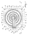
- first circuit 7 On the bottom 5 of the seat 3 there is at least one first circuit 7, which is constituted by a first track 7a and by a second track 7b, both of which are made of electrically conducting material, constituted for example by a silver compound that is commonly used in screen printing and is deposited by means of an appropriate screen printing method.
- the first track 7a can be shaped like a disk or circle, is arranged coaxially with respect to the axis 4 of the seat 3, and has a first appendage 7c, also made of the same material, that protrudes radially from it and reaches, at one of its ends 7d, the upper face 2a of the container 2, on the outside of the seat 3.
- the second track 7b made of a material that is similar to the one used for the first track 7a, is shaped like a circular arc, is concentric to the first track 7a, and is arranged externally to it at a minimal distance so as to not be in contact with it.
- the second track 7b is arranged so that the region in which it is open is located at the first appendage 7c of the first track 7a, so as to be insulated electrically from them.
- the circular arc along which the second track 7b lies has a breadth that leaves out only the region needed to avoid electrical contact with the first appendage 7c, for example approximately equal to 7/8 (seven eighths) of the full circle or more.
- a second appendage 7e protrudes from one end of the second track 7b, is preferably parallel to the first tab 7c, and likewise reaches, at an end 7f, the surface 2a of the container 2, outside the seat 3.
- the first circuit 7 is accordingly open, since the first track and the second track are not in contact with each other in any point, and has two terminals, constituted by the ends 7d and 7f of the first and second appendages, which can be placed in contact with an electronic device for processing electrical signals by means of a terminal strip 8 and electrical conductors.
- a second circuit 9 can also be provided on the bottom 5 of the seat 3 and is composed of a third track 9a and of a fourth track 9b, likewise provided by depositing an electrically conducting material.
- the third track is shaped like a circular arc, is arranged concentrically with respect to the first and second tracks 7a and 7b, and is accordingly coaxial to the axis 4 of the seat 3 and located at a preset distance from the second track 7b, so that a first gap 10, substantially shaped like a circular arc and on which no conducting material is deposited, is formed between said second and third tracks.
- the third track 9a also has an extension that leaves out only the region required to avoid electrical contact with the first and second appendages 7c and 7e.
- a third appendage 9c arranged parallel to the first and second appendages, protrudes from one end of the third track 9a and reaches, at one of its ends 9d, the surface 2a of the container 2 outside the seat 3.
- the fourth track 9b is shaped like a circular arc, is concentric with respect to the third track 7a, and is arranged externally thereto at a minimal distance, so that no contact with it occurs.
- the fourth track is arranged on the bottom 5 of the seat 3, so that one of its ends is in contact with the second appendage 7e, while its extent is such as to completely surround the third track 9a, leaving free only the region needed to avoid making contact with the first and third tracks 7c and 9c.
- the fifth track is shaped like a circular arc and is arranged concentrically with respect to the first, second, third and fourth tracks, and is therefore coaxial with respect to the axis 4 of the seat 3 and located at a preset distance from the fourth track 9b, so that a second gap 12, shaped substantially like a circular arc, on which no conducting material is deposited is formed between said fourth track and said fifth track.
- the second gap 12 is larger, in a radial direction, than the first gap 10, so that the distance between the fourth track 9b and the fifth track 10a is larger than the distance between the second track 7b and the third track 9a.
- the fifth track 11 a has an extension that leaves out only the region needed to avoid electrical contact with the first, second and third appendages 7c, 7e and 9c.
- a fourth appendage 11c arranged parallel to the first, second and third appendages, protrudes from one end of the fifth track 11a and reaches, at one of its ends 11d, the surface 2a of the container 2, outside the seat 3.
- the sixth track 11b is shaped like a circular arc, is concentric with respect to the fifth track 11a, and is arranged externally to it at a minimal distance so as to not be in contact with it.
- the sixth track is arranged on the bottom 5 of the seat 3, so that one of its ends is in contact with the second appendage 7e, while its extension is such as to surround completely the fifth track 11a, leaving free only the region required to avoid making contact with the first, third and fourth tracks 7c, 9c and 11c.
- the fourth and fifth circuits are provided like the second and third circuits, said seventh, eighth, ninth and tenth tracks being constituted by circular arcs and being concentric with respect to each other and to the tracks arranged further inward with respect to them, so as to be coaxial with respect to the axis 4 of the seat 3.
- the seventh track 13a and the ninth track 14a respectively have, at one of the ends, a fifth appendage 13c and a sixth appendage 14c, which protrude parallel to the first appendage 7c, respectively at one of the ends 13d and 14d, up to the surface 2a of the container 2, outside the seat 3.
- the eighth track 13b and the tenth track 14b are arranged respectively externally with respect to the seventh and ninth tracks, at a minimal distance from them required to avoid their contact, so as to be electrically insulated from them.
- the eighth and tenth tracks are arranged so as to surround approximately completely the seventh and ninth tracks, one of their ends being arranged in contact with the second appendage 7e.
- the fourth circuit 13 is arranged at a chosen radial distance from the third circuit 11, so that a third gap 15 is formed between them.
- a fourth gap 16 is formed between the fourth circuit 13 and the fifth circuit 14.
- the fourth gap 16 may be radially larger than the third gap 15, which in turn can be larger than the second gap 12, so that said gaps formed between two radially consecutive circuits increase in size as one moves toward the outside of the seat 3.
- the circuits can be arranged on the bottom 5 of the concave seat 3 in a number that is sufficient to affect the entire extension of the bottom 5, said number being variable according to the dimensions of the seat 3 and to the arrangement of the gaps formed between two consecutive circuits.
- each circuit is composed of two tracks shaped like a sector, which are concentric and mutually spaced by a minimal distance required to prevent their mutual electrical contact; one of the tracks, the outermost one in the example, is in contact with a first tab, which acts as ground for an electronic device for processing the signal supplied by the sensor 1, while the second track, for example the innermost one, has a tab that reaches the outside of the seat 3, where it is arranged in contact with an input of said signal processing device.
- the width of each one of the tracks provided on the bottom 5 of the seat 3 can be comprised for example between 0.7 millimeters and 1 millimeter, while the radial distance between two tracks that belong to the same circuit may conveniently be comprised for example between 0.3 and 0.5 millimeters.
- a convenient value for the outside diameter of the first track 7a is instead comprised by way of example between approximately 3.5 and 5 millimeters.
- Each one of such circuits is further arranged concentrically with respect to all the others, and each one is separated from the next, in a radial direction, by a gap whose dimensions can advantageously increase as the distance of the affected circuits with respect to the axis 4 increases.
- the first gap provided between the first and second circuits has a radial width of approximately one millimeter
- the second gap has a width of approximately two millimeters
- the third gap has a width of approximately three millimeters, and this width accordingly increases by approximately one millimeter between one gap and the next, up to the outermost circuit.
- the radial width of the gaps and their rule of radial variation may of course be any, in order to obtain the intended sensitivity and precision from the sensor 1, especially in view of the fact that the distribution of the circuits on the bottom 5 is closely correlated to the radial profile 6 of the bottom.
- the sensor 1 further comprises a contact body 17, which is preferably constituted by a ball of electrically conducting material or by a drop of mercury.
- the contact body is free to perform a translational movement on the bottom 5 of the seat 3, and its dimensions are such that the surface on which it makes contact or rests on the radial profile 6 is smaller than the width of the first track 7a, so that if the axis of the seat 3 is arranged vertically, it interacts on a region that is completely contained within said first track, according resting only thereon.
- the surface with which the contact body 17 rests on the bottom 5 of the seat 3 is greater than the radial distance that separates the two concentric tracks of each circuit, so that it is possible to provide an electrical contact between them, but is in any case smaller than the radial distance that separates two consecutive circuits.
- the seat 3 can be closed in an upper region by means of a lid 18, which is made of insulating and transparent material, preferably plastic material, so as to protect the hollow seat 3 and the contact body 17 arranged inside it against external agents, which may cause the motion of said body to become uneven, at the same time allowing direct viewing from the outside of said contact body and of the circuits provided on the bottom of the seat.
- a lid 18 is made of insulating and transparent material, preferably plastic material, so as to protect the hollow seat 3 and the contact body 17 arranged inside it against external agents, which may cause the motion of said body to become uneven, at the same time allowing direct viewing from the outside of said contact body and of the circuits provided on the bottom of the seat.
- the lid 18 can be coupled to the container 2 at the upper face 2a of said container by ultrasound welding, thus providing an excellent tightness of the seat 3, which is aimed at preventing even an unintentional escape of the contact body contained therein.
- the container 2 has advantageously associated means suitable to allow adjustments of flatness and/or means suitable to keep it suspended with respect to a fixed supporting surface.
- the container 2 rests, by means of a lower end face 19 thereof, on a first plate 20, which is constituted for example by an aluminum lamina rigidly coupled thereto, and the upper surface 21 of which protrudes from the base 19 in at least one point.
- the first plate 20 may have a square or rectangular plan shape and may protrude from the base 19 of the container 2 at its four corners, so as to constitute for example four flaps 22.
- a hole 23 is formed at each one of the flaps and has an axis that is parallel to the axis 4 of the seat 3; a screw 24 that is completely or partially threaded at its end can be inserted in each one of said holes.
- a preferably helical spring 25 is arranged coaxially to the stem 24a of each one of the screws 24 so as to surround part of said stem, a first upper end 25a of which abuts against the lower surface 26 of the plate 20.
- the sensor 1 further comprises a fixed support 27, which is constituted for example by a second plate 28, which is preferably flat and is provided with a plurality of bushes 29, which protrude vertically upward, are threaded internally, are equal in number to the screws 24, and are arranged in a manner that duplicates the arrangement of the holes 23 provided in the first plate 20.
- a fixed support 27 which is constituted for example by a second plate 28, which is preferably flat and is provided with a plurality of bushes 29, which protrude vertically upward, are threaded internally, are equal in number to the screws 24, and are arranged in a manner that duplicates the arrangement of the holes 23 provided in the first plate 20.
- the fixed support 27 can be arranged below the first plate 20, so that the bushes 29 are arranged at the holes 23, so that each one accommodates part of the stem of one of the screws 24, so as to provide an interconnection between the container 2 and the fixed support 27.
- a second end 25b of one of the springs 25 abuts against the upper surface 29a of each one of the bushes; the springs are thus interposed between the first plate 20 and the second plate 28 and are rigidly coupled in this position around part of the stem 25a of the screws 24.
- the second plate 28 can then be fixed to a structure that is rigidly coupled to the ground, to the building or to the machine whose vibrations or movements are to be detected, so that its bushes protrude upward in an approximately vertical direction.
- the operation of the sensor 1 according to the invention entails that once the second plate 28 has been fixed as described above, the orientation of the first plate 20 and accordingly of the container 2 that is rigidly coupled thereto is determined precisely by acting on one or more of the threaded screws 24, in the direction of greater or lesser tightening, respectively if one wishes to move one of the flaps 22 closer or further apart with respect to the plate 28, thus producing an upward or downward movement thereof.
- the springs 25 also contribute to this adjustment and by acting in contrast with the screws 24 keep the first plate 20 in contact with the heads of the screws 25, supporting the container 2.
- the contact body 17 rests only on the first track 7a, since its diameter is smaller than the outside diameter of said first track, so that all the circuits provided on the bottom 5 of the seat 3 are open because no contact occurs between the tracks that compose them.
- the contact body 17, which is not rigidly coupled to the container 2 and which owing to its teardrop or spherical shape can move on the bottom 5 of the seat 3 with very low friction, performs a relative motion with respect to said seat, rising along the bottom 5 by an extent that is proportional to the intensity of the force applied to said sensor.
- the contact body 17 performs, with respect to the bottom 5, an alternating rising and falling motion on a plurality of portions of said bottom.
- the contact body 17 crosses at least one of the circuits provided on the bottom of the seat 3, providing a contact between the two concentric tracks that compose them.
- an electrical pulse to an electrical signal processing device, which in turn can activate an alarm device, such as for example a sound or light source, warning the occupants of a building or anyone in the vicinity of the imminence of a potential danger.
- an alarm device such as for example a sound or light source
- the circular plan shape of the seat 3 and the arrangement of the likewise circular tracks on its bottom 5 allow the sensor 1 to detect movements and oscillations in any direction of the plane, eliminating the need to use at least two sensors arranged in two different directions, as provided by the background art.
- the initial calibration by way of which the contact element 17 is centered perfectly on the bottom 5 of the seat 3, allows a uniform response of the instrument along any direction of a plane.
- the sensor 1 may further emit a signal that is proportional to the amplitude of the oscillations by which it is affected, since according to the pair of tracks short-circuited by the contact element 17 it is possible to determine the height to which said contact element has risen along the bottom 5 of the seat 3.
- the response curve of the sensor can be chosen according to the operating requirements by acting on the radial profile 6 of the bottom 5, particularly on its curvature, and on the radial distance at which the circuits are arranged.
- the distance between each pair of tracks that form a circuit and the next pair increases from the inward circuits to the outward circuits; however, excellent results can be achieved with different arrangements.
- Such sensor can be used advantageously for prompt sensing of seismic phenomena, since it is capable of reacting when affected by the first oscillations, which often precede the catastrophic event, allowing anyone who is in the vicinity to react rapidly.
- a sensor for detecting vibrations, particularly seismic waves having been devised which is capable of providing a signal that is derived from the sensing of an acceleration imparted thereto along any direction of a plane.
- Another object achieved by the invention is to be constructively simple, compact and easy to calibrate.
- Another important object that is achieved is to provide a sensor that can offer an immediate response to an externally originated force.
Landscapes
- Physics & Mathematics (AREA)
- Life Sciences & Earth Sciences (AREA)
- Engineering & Computer Science (AREA)
- Acoustics & Sound (AREA)
- Environmental & Geological Engineering (AREA)
- Geology (AREA)
- Remote Sensing (AREA)
- General Life Sciences & Earth Sciences (AREA)
- General Physics & Mathematics (AREA)
- Geophysics (AREA)
- Geophysics And Detection Of Objects (AREA)
- Measurement Of Mechanical Vibrations Or Ultrasonic Waves (AREA)
Applications Claiming Priority (2)
| Application Number | Priority Date | Filing Date | Title |
|---|---|---|---|
| IT000012A ITTV20040012A1 (it) | 2004-02-02 | 2004-02-02 | Sensore per il rilevamento di vibrazioni, particolarmente di onde sismiche. |
| ITTV20040012 | 2004-02-02 |
Publications (2)
| Publication Number | Publication Date |
|---|---|
| EP1560042A2 true EP1560042A2 (fr) | 2005-08-03 |
| EP1560042A3 EP1560042A3 (fr) | 2006-10-11 |
Family
ID=34640407
Family Applications (1)
| Application Number | Title | Priority Date | Filing Date |
|---|---|---|---|
| EP05100534A Withdrawn EP1560042A3 (fr) | 2004-02-02 | 2005-01-27 | Capteur de détection de vibrations, en particulier de vibrations sismiques |
Country Status (2)
| Country | Link |
|---|---|
| EP (1) | EP1560042A3 (fr) |
| IT (1) | ITTV20040012A1 (fr) |
Cited By (3)
| Publication number | Priority date | Publication date | Assignee | Title |
|---|---|---|---|---|
| RU2306611C1 (ru) * | 2006-01-10 | 2007-09-20 | Федеральное государственное унитарное предприятие "Научно-исследовательский и конструкторский институт радиоэлектронной техники" ФГУП "НИКИРЭТ" | Сейсмическое устройство обнаружения движущихся объектов |
| RU2394277C2 (ru) * | 2008-09-29 | 2010-07-10 | Сергей Николаевич Сысоев | Система обнаружения попыток проникновения на охраняемую территорию |
| RU184012U1 (ru) * | 2017-12-12 | 2018-10-11 | Федеральное государственное казенное образовательное учреждение высшего профессионального образования "Калининградский пограничный институт Федеральной службы безопасности Российской Федерации" | Устройство распознавания движущихся объектов по сейсмическому сигналу |
Family Cites Families (3)
| Publication number | Priority date | Publication date | Assignee | Title |
|---|---|---|---|---|
| US4001185A (en) * | 1972-06-28 | 1977-01-04 | Matsushita Electric Industrial Co., Ltd. | Acceleration sensing device |
| FR2686421B1 (fr) * | 1990-11-29 | 1994-05-13 | Peugeot Automobiles | Element detecteur de valeurs limites determinees d'accelerations longitudinales et transversales d'un vehicule et dispositif de commande electrique d'elements de suspension active du vehicule utilisant un tel element . |
| US5644086A (en) * | 1996-10-08 | 1997-07-01 | Tokyo Gas Co., Ltd. | Preloaded linear beam vibration sensor |
-
2004
- 2004-02-02 IT IT000012A patent/ITTV20040012A1/it unknown
-
2005
- 2005-01-27 EP EP05100534A patent/EP1560042A3/fr not_active Withdrawn
Cited By (3)
| Publication number | Priority date | Publication date | Assignee | Title |
|---|---|---|---|---|
| RU2306611C1 (ru) * | 2006-01-10 | 2007-09-20 | Федеральное государственное унитарное предприятие "Научно-исследовательский и конструкторский институт радиоэлектронной техники" ФГУП "НИКИРЭТ" | Сейсмическое устройство обнаружения движущихся объектов |
| RU2394277C2 (ru) * | 2008-09-29 | 2010-07-10 | Сергей Николаевич Сысоев | Система обнаружения попыток проникновения на охраняемую территорию |
| RU184012U1 (ru) * | 2017-12-12 | 2018-10-11 | Федеральное государственное казенное образовательное учреждение высшего профессионального образования "Калининградский пограничный институт Федеральной службы безопасности Российской Федерации" | Устройство распознавания движущихся объектов по сейсмическому сигналу |
Also Published As
| Publication number | Publication date |
|---|---|
| EP1560042A3 (fr) | 2006-10-11 |
| ITTV20040012A1 (it) | 2004-05-02 |
Similar Documents
| Publication | Publication Date | Title |
|---|---|---|
| US4297690A (en) | Earthquake alarm system | |
| US4344004A (en) | Dual function transducer utilizing displacement currents | |
| US5001466A (en) | Earthquake detector | |
| US9417217B2 (en) | System for detecting and locating a disturbance in a medium and corresponding method | |
| US20050066736A1 (en) | Piezoelectric vibration sensor | |
| US4603484A (en) | Level sensing apparatus providing output signals compatible with digital apparatus | |
| US4051397A (en) | Two sensitivity level kinetic sensor | |
| US5539387A (en) | Earthquake sensor | |
| US20140062258A1 (en) | External force detection equipment and external force detection sensor | |
| JP2002181535A (ja) | 傾斜センサ | |
| KR101938825B1 (ko) | 전방위 진동감지센서 및 이를 이용한 지진 재해 경보장치 | |
| US3418546A (en) | Momentum transducer | |
| EP1560042A2 (fr) | Capteur de détection de vibrations, en particulier de vibrations sismiques | |
| US4585082A (en) | Weight scale utilizing a capacitative load cell | |
| US4325259A (en) | Vibration amplitude measuring device | |
| AU721303B2 (en) | Earthquake sensor | |
| US4712627A (en) | Calibration of weight scale utilizing a capacitative load cell | |
| JPH1062234A (ja) | 簡易型地震感知警報器 | |
| US4629019A (en) | Weight scale utilizing a capacitative load cell | |
| MXPA97006603A (en) | Sensor of sis | |
| RU2438151C1 (ru) | Гравитационный вариометр | |
| JP2006208231A (ja) | 簡易地震計 | |
| US12333920B2 (en) | Earthquake detection and alarm unit and system | |
| GB2071320A (en) | Measuring instrument | |
| KR100479934B1 (ko) | 저주파 진동 측정용 가속도 센서 |
Legal Events
| Date | Code | Title | Description |
|---|---|---|---|
| PUAI | Public reference made under article 153(3) epc to a published international application that has entered the european phase |
Free format text: ORIGINAL CODE: 0009012 |
|
| AK | Designated contracting states |
Kind code of ref document: A2 Designated state(s): AT BE BG CH CY CZ DE DK EE ES FI FR GB GR HU IE IS IT LI LT LU MC NL PL PT RO SE SI SK TR |
|
| AX | Request for extension of the european patent |
Extension state: AL BA HR LV MK YU |
|
| PUAL | Search report despatched |
Free format text: ORIGINAL CODE: 0009013 |
|
| AK | Designated contracting states |
Kind code of ref document: A3 Designated state(s): AT BE BG CH CY CZ DE DK EE ES FI FR GB GR HU IE IS IT LI LT LU MC NL PL PT RO SE SI SK TR |
|
| AX | Request for extension of the european patent |
Extension state: AL BA HR LV MK YU |
|
| AKX | Designation fees paid | ||
| REG | Reference to a national code |
Ref country code: DE Ref legal event code: 8566 |
|
| STAA | Information on the status of an ep patent application or granted ep patent |
Free format text: STATUS: THE APPLICATION IS DEEMED TO BE WITHDRAWN |
|
| 18D | Application deemed to be withdrawn |
Effective date: 20070502 |