EP1560167A2 - Motorkontrollkarte mit Mikroserver - Google Patents
Motorkontrollkarte mit Mikroserver Download PDFInfo
- Publication number
- EP1560167A2 EP1560167A2 EP04257157A EP04257157A EP1560167A2 EP 1560167 A2 EP1560167 A2 EP 1560167A2 EP 04257157 A EP04257157 A EP 04257157A EP 04257157 A EP04257157 A EP 04257157A EP 1560167 A2 EP1560167 A2 EP 1560167A2
- Authority
- EP
- European Patent Office
- Prior art keywords
- microserver
- deployed product
- engine
- web page
- internet
- Prior art date
- Legal status (The legal status is an assumption and is not a legal conclusion. Google has not performed a legal analysis and makes no representation as to the accuracy of the status listed.)
- Withdrawn
Links
Images

Classifications
-
- G—PHYSICS
- G06—COMPUTING OR CALCULATING; COUNTING
- G06Q—INFORMATION AND COMMUNICATION TECHNOLOGY [ICT] SPECIALLY ADAPTED FOR ADMINISTRATIVE, COMMERCIAL, FINANCIAL, MANAGERIAL OR SUPERVISORY PURPOSES; SYSTEMS OR METHODS SPECIALLY ADAPTED FOR ADMINISTRATIVE, COMMERCIAL, FINANCIAL, MANAGERIAL OR SUPERVISORY PURPOSES, NOT OTHERWISE PROVIDED FOR
- G06Q10/00—Administration; Management
- G06Q10/06—Resources, workflows, human or project management; Enterprise or organisation planning; Enterprise or organisation modelling
-
- H—ELECTRICITY
- H04—ELECTRIC COMMUNICATION TECHNIQUE
- H04L—TRANSMISSION OF DIGITAL INFORMATION, e.g. TELEGRAPHIC COMMUNICATION
- H04L67/00—Network arrangements or protocols for supporting network services or applications
- H04L67/01—Protocols
- H04L67/02—Protocols based on web technology, e.g. hypertext transfer protocol [HTTP]
-
- H—ELECTRICITY
- H04—ELECTRIC COMMUNICATION TECHNIQUE
- H04L—TRANSMISSION OF DIGITAL INFORMATION, e.g. TELEGRAPHIC COMMUNICATION
- H04L67/00—Network arrangements or protocols for supporting network services or applications
- H04L67/01—Protocols
- H04L67/02—Protocols based on web technology, e.g. hypertext transfer protocol [HTTP]
- H04L67/025—Protocols based on web technology, e.g. hypertext transfer protocol [HTTP] for remote control or remote monitoring of applications
-
- H—ELECTRICITY
- H04—ELECTRIC COMMUNICATION TECHNIQUE
- H04L—TRANSMISSION OF DIGITAL INFORMATION, e.g. TELEGRAPHIC COMMUNICATION
- H04L67/00—Network arrangements or protocols for supporting network services or applications
- H04L67/01—Protocols
- H04L67/04—Protocols specially adapted for terminals or networks with limited capabilities; specially adapted for terminal portability
-
- H—ELECTRICITY
- H04—ELECTRIC COMMUNICATION TECHNIQUE
- H04L—TRANSMISSION OF DIGITAL INFORMATION, e.g. TELEGRAPHIC COMMUNICATION
- H04L67/00—Network arrangements or protocols for supporting network services or applications
- H04L67/01—Protocols
- H04L67/12—Protocols specially adapted for proprietary or special-purpose networking environments, e.g. medical networks, sensor networks, networks in vehicles or remote metering networks
-
- H—ELECTRICITY
- H04—ELECTRIC COMMUNICATION TECHNIQUE
- H04L—TRANSMISSION OF DIGITAL INFORMATION, e.g. TELEGRAPHIC COMMUNICATION
- H04L69/00—Network arrangements, protocols or services independent of the application payload and not provided for in the other groups of this subclass
- H04L69/30—Definitions, standards or architectural aspects of layered protocol stacks
- H04L69/32—Architecture of open systems interconnection [OSI] 7-layer type protocol stacks, e.g. the interfaces between the data link level and the physical level
- H04L69/322—Intralayer communication protocols among peer entities or protocol data unit [PDU] definitions
- H04L69/329—Intralayer communication protocols among peer entities or protocol data unit [PDU] definitions in the application layer [OSI layer 7]
-
- G—PHYSICS
- G07—CHECKING-DEVICES
- G07C—TIME OR ATTENDANCE REGISTERS; REGISTERING OR INDICATING THE WORKING OF MACHINES; GENERATING RANDOM NUMBERS; VOTING OR LOTTERY APPARATUS; ARRANGEMENTS, SYSTEMS OR APPARATUS FOR CHECKING NOT PROVIDED FOR ELSEWHERE
- G07C5/00—Registering or indicating the working of vehicles
- G07C5/008—Registering or indicating the working of vehicles communicating information to a remotely located station
Definitions
- the present disclosure generally relates to integrated Internet systems and, more particularly, relates to the provision of an Internet portal onboard a deployed product.
- On-demand maintenance usually when a product breaks
- scheduled maintenance based upon the best estimate of a manufacturer as to when something will wear out with normal usage
- condition based maintenance maintenance that occurs when maximum usage is obtained from a part but just prior to part failure.
- On demand maintenance is self-explanatory. It is when a component fails and has to be repaired or replaced. This normally occurs as an end result of its operators not understanding its component life or the conditions of its use, and the highest costs, both physical and lost time, are associated with it.
- Scheduled maintenance is less costly but can be very wasteful. Depending upon the usage of the product, one may be replacing parts that still have a significantly useful life.
- condition-based maintenance is the holy grail of maintenance in many industries. If a manufacturer or service organization can accurately ascertain the maximum life of a component based upon actual wear, tear, and usage, it could then allow for the optimized, just-in-time servicing and replacement of that component, thereby allowing for the user to gain maximum product life and to schedule the replacement at a non-critical time. As a result, a manufacturer utilizing condition based maintenance could better plan its spares production and save millions of dollars in unnecessary production, warehousing and inventory taxes.
- EDUs engine data'units
- EEC electronic engine control
- a number of industries normally attempt to gather product usage intelligence through manual inspections and, more recently, laptop computer downloads performed concurrently with scheduled or on-demand maintenance service calls. This is normally accomplished by one of two methods: sending the service person to the product, bringing the product to a service center, or both.
- Examples of the former include products with fixed installations, such as elevators, HVAC systems, nuclear power plants, and large home appliances. Examples of the latter include automobiles, small home appliances, home electronics equipment, lawn-mowers, or anything small enough to be easily carried or shipped. Both methods are inefficient and result in significant down time.
- a gas turbine engine which comprises a compressor section, a combustion section, a turbine section, a casing, an electronic control box, and a microserver card.
- the combustion section is downstream of the compressor section while the turbine section is downstream of the combustion section.
- the casing surrounds the compressor section, combustion section and turbine section.
- the electronic control box is mounted to the casing and controls and monitors operation of the engine, while the microserver card is mounted in the electronic control box.
- a system for communicating with the deployed product which comprises a deployed product, an electronic control box mounted to the deployed product, a microserver card and a computing device.
- the microserver card is mounted in the electronic control box and , receives data about the deployed product and hosts a web page through which the received data is accessible.
- the computing device is remote from the deployed product and is adapted to wirelessly access the microserver web page.
- the deployed product which comprises a housing, an electronic control box mounted to the housing, and a microserver card mounted in the electronic control box.
- the microserver hosts a web page and generates a wireless system around the deployed product.
- a method of communicating with the deployed product comprises the steps of installing a microserver card into an electronic control box of the deployed product, hosting a web page on the microserver card, and accessing the web page wirelessly over the Internet.
- an electronic controller for an engine which comprises means for controlling the engine, and a microserver for generating a wireless system adapted to connect to the Internet.
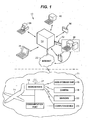
- FIG. 1 is a schematic representation of an integrated system for monitoring, gathering data about, and disseminating data about a deployed product in accordance with one embodiment of the present disclosure
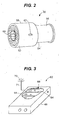
- FIG. 2 is a perspective view of one embodiment of a gas turbine engine constructed in accordance with the teachings of the disclbsure;
- FIG. 3 is a perspective view of a engine controller retrofitted with one embodiment of a microserver card in accordance with the teachings of the disclosure.
- FIG. 4 is a block diagram illustrating one embodiment of a system for communicating with a deployed product in accordance with the teachings of the disclosure.
- a system 10 is presented which is capable of monitoring a deployed product, gathering data about the deployed product, and disseminating the data to interested parties. It is also capable of monitoring and restricting access to its data, and can accept data for storage or integration within the product itself, such as firmware revision updates.
- the term "deployed product” has broad applicability and refers to any product, component, or system on a variety of machines including but not limited to a vehicle, a HVAC system, or an elevator/escalator system, such as a propulsion system on a vehicle, a compartment of a vehicle, or a braking system for a vehicle, wherein the vehicle is any one of a number of movable devices including aircraft and elevator cars.
- the system 10 includes a server 12 located on the deployed product or movable platform 14.
- the movable platform 14 may be a boat, an airplane, a spacecraft, an automobile, a truck, or any pther entity that is movable with an airplane being depicted for ease of understanding.
- the server 12 may monitor the condition of and/or gather data about the deployed product in a number of ways.
- the server 12 may be connected to or integrated with a vehicle data storage unit 16 which contains data about the deployed product.
- the server 12 may also be connected to a video camera 18, such as video web camera, to provide pictures, in real-time or on a delayed basis, of the deployed product.
- the server 12 may be connected to a number of sensors 20, such as a vibration sensor or a temperature sensor, which provide additional or environmental information about the condition of the deployed product.
- the server 12 may be programmed in any suitable language known in the art to gather the data about the deployed product and present the data to interested parties in a desired format.
- the server 12 may be used to host a web page which provides information about one or more deployed products on the movable platform.
- the web page may have a menu which allows an interested party to gain access to gathered data about a particular deployed product.
- the data about the deployed product(s) may be organized on the server 12 and presented in any desirable format or manner.
- the server 12 may also be programmed to allow an interested party to carry out diagnostic operations on the deployed product(s) and/or to upgrade software associated with the deployed product(s).
- a wireless system or intranet 21 is provided around the entire deployed product 14 enabling wireless communication to any electronic device thereon as will be described in further detail herein.
- the server 12 may be provided with a local USB or other communications port 22 for direct hook-up.
- a mechanic or engineer could then gain access to the server 12 by hooking up a promtop, laptop computer or another device 23 such as a video borescope or a bar code reader to the communications port 22.
- Other examples of communication ports through which access may be gained to server 12 include wireless peer-to-peer communication links.
- the mechanic or engineer could then conduct a desired diagnostic operation or even fix a problem with the deployed product.
- any passenger on board the deployed product 14 could use his or her own computer device 23 to access the server 12 and thus the Internet 25, again as will be described in further detail herein.
- the server 12 may comprise any suitable computer or processing unit known in the art.
- the server 12 may be a hand-held sized microserver using a Linux-based operating system or, as will be described in further detail herein, may be a card adapted to be inserted into a larger computing device. Further, the server 12 may be provided with its own web address, a firewall, and security protocols known only to selected individuals, such as the manufacturer of the deployed product.
- the server 12 is capable of being accessed by interested parties via a portal 24 and the Internet or world wide web 25.
- the server 12 may have a communications device, such as a modem, built within it to allow communication between the server 12 and the portal 24.
- the communication device may allow for radio frequency communications such as cellular communication, satellite communication, and/or wireless communication between the server 12 and the portal 24.
- communications between the server 12 and the portal 24 may be achieved by optical means such as an infrared link.
- the portal 24 is hosted by an external server which may be any suitable server known in the art.
- the server hosting the portal 24 also has appropriate communication means associated with it to allow it to gain access to and be accessed by the server 12.
- Data gathered by and stored on the server 12 may be downloaded to the portal 24 as desired.
- the server 12 may be programmed to periodically download data to the server hosting the portal 24 or to download data on specific events such as when an aircraft lands or when a truck or automobile reaches a particular destination.
- the server 12 may also download data to the portal 24 upon the activation of a switch by an operator onboard the moving platform.
- the portal server may upload data to the microserver, such as product firmware revisions or technical manuals for access by interested parties.
- the server 12 may include an antenna 27 or the like to facilitate such wireless communication.
- the portal 24 may be provided with a number of software tools called gadgets to automatically analyze, organize, and sort the data which has been received from the server 12.
- the data is preferably sorted so that different communities gain access to different portions of the data. For example, actual and potential customers of a vendor of a deployed product may form one community and have access to certain data, while support engineers and product designers may form a second community and have access to another form of the data.
- the portal 24 offers great flexibility as to how and to whom the data is disseminated.
- the portal 24 provides virtual shared spaces which allow for the common space posting and access of information about, a deployed product in a shared awareness between customers, support engineers, field operatives, and even product designers.
- the portal 24 may also be designed to provide chat rooms, bulletin boards, and on-line meeting capabilities where interested parties can communicate with each other.
- One of the advantages to using the portal 24 is that its functionality can be carried out in a secure, user friendly, web-based environment. Members of a particular community can log in by presenting an identification and/or a password and gain access to current information about a deployed product. Another advantage to using the portal 24 is that it can be used to upload data, information, instructions, software, technical publications, diagnostic programs, etc. to the server 1,2. Thus, an engineer can perform diagnostic tests on a deployed product from a remote location using the Internet. Similarly, a service engineer working on the aircraft can gain access to a technical publication outlining how to regain a certain situation, for example, through the server 12. As the communication is two way, access, upload, download, and execution of all such information and, data can be performed at the deployed product or remote locations.
- Access to the portal 24 may be gained in a number of different ways by a variety of devices as described below.
- an interested party can communicate with the portal 24 through his/her personal computer 38 and the web browser on the computer 38.
- the computer 38 may be a PC workstation at the office of a user or a laptop or PC at the home of the user. Even a computer 40 in an Internet café may be used to gain access to the portal 24.
- a wireless PC tablet 36 on the shop floor of a manufacturer of the deployed product may also be used to communicate with the portal 24.
- the portal 24 may also be in communication with the internal network 30 of the manufacturer of or a vendor of the deployed product.
- a secure data pipe 32 may be used for crawlers for automated data exchange.
- the portal 24 may communicate with the internal network 30 via a wireless PDA.
- the system 10 may also be configured to allow the internal network 30 to communicate directly with the server 12 via the Internet by dialing up the web address for the server 12.
- a firewall may be provided between the internal network 30 and the server 12.
- the system 10 of the present disclosure has broad applicability and can be used for a wide variety of purposes.
- the system 10 can be used by an engineer working for a manufacturer of the deployed product to gain access to the server 12 and to then carry out a diagnostic operation or a fix on a particular deployed product. All of this can be carried out while the movable platform 14 is in motion and in a location remote from the engineer, thus avoiding having to return a deployed product to a manufacturer for diagnosis and repair.
- the system 10 may also be used to check the status of a deployed product.
- an operator of a fleet of airplanes having a network 30 may contact the server 12 on a particular airplane, either directly or through the portal 24, and learn the location of and the status of that airplane.
- a manufacturer of a jet engine may access the server 12 through its network, again either directly or through the portal 24, to ascertain the condition of a particular jet engine or a particular component on the jet engine to determine when that engine or component may require servicing, and to collect data in determining product and fleet averages for improved product design and support. This can save the manufacturer unnecessary warranty, maintenance wear, and spare parts production costs.
- the server 12 may be installed in the cabin of an aircraft, by using existing test ports already wired into the engine/airframe.
- a gas turbine engine retrofitted or constructed in accordance with the teachings of the present disclosure is generally referred to by reference numeral 50. While the following description will be given with respect to the engine 50, it is to be understood that the teachings of the disclosure can be used in conjunction with any other deployed product to generate a wireless system around the deployed product and thus make two-way wireless communication between the deployed product and a remote computing device possible.
- the gas turbine engine generally includes a compressor section 52, a combustion section 54, and a turbine section 56 surrounded by a fan case 58.
- Rotation of the compressor section 52 causes ambient air to be ingested and compressed before being communicated to though a diffuser and into the combustion section 54.
- the combustion section 54 the compressed air is combined with fuel and ignited, thereby generating hot, rapidly expanding combustion gases which get communicated to the turbine section 56.
- the blades (not shown) of the turbine section 56 rotate as a result, and as they are mounted to the same shaft assembly 60 as the compressor section 52, the engine cycle is perpetuated. '
- an electronic controller or control box 62 is mounted to the fan case 58.
- the controller 62 is wired to various components and sensors in the engine 50 for operation, modification and recordation of engine operation.
- the controller 62 can be provided in many forms including, but not limited to, a FADEC (Full Authority Digital Electronic Control) or EEC (Electronic Engine Control), and may include a number of circuitry boards or cards 64 mounted within a housing 66.
- the controller 62 may work in conjunction with an EDU (Electronic Data Unit) or Data Management Unit (DMU) for storage of data related to engine operation.
- EDU Electronic Data Unit
- DMU Data Management Unit
- the means for controlling the engine may employ any known technology, but generally performs as an electronic fuel control or injector taking power and throttle commands/signals from the cockpit and adjusting engine control to provide the desired power.
- the EEC or other electronic control may include a plurality of cards or boards, including a motherboard, slidably mounted in a rack of the EEC.
- the cards/boards receive inputs from the cockpit and various engine sensors, and outputs signals to various valves and controls on the engine to effectuate its operation.
- the engine controller 62 further includes a microserver engine control card 68.
- the microserver engine control card 68 can be installed in the housing 66 along with the other cards 64 and immediately provide a relatively inexpensive apparatus and method by which the existing engine controller 62 can generate a wireless system enabling two-way wireless communication through the Internet.
- the microserver card 18 generates a local wireless system or intranet 70 in and around the deployed product capable of operating in conjunction with, or independent from, the Internet.
- An antenna 71 may be provided to facilitate such communication.
- the wireless system 70 is generated around the entire deployed product, in this case including the engine 50 and the entire aircraft 72 to which the engine 50 is attached.
- This wireless system 70 enables significant communication on many levels as will described in detail below.
- the wireless system 70 enables communication with remote locations such as remote computing devices 73.
- the microserver card 68 may serve as a host for a web page accessible through the Internet 74.
- individuals wishing to gain information as to the operating data generated by the engines 50 can simply log into the given website for that engine by way of the Internet 74 and the remote computing device 73 and be immediately connected to the microserver 68, and in turn be made privy to the data'associated with the engine 50.
- the remote computing device 73 can be provided in the form of any currently known or understood computing device including, but not limited to, laptop computers 76, desktop computers 78, personal digital assistants 80, wireless PC tablets 82, and cellular phones 84.
- the wireless system 70 may connect to the Internet 74 by any number of mechanisms including a local area network (LAN) 86, a cellular network 87, and a satellite 88.
- LAN local area network
- the microserver card 68 further enables wireless communication with various engine sensors 90 and RF (radio frequency) identification tags 92 of components within the engine 50. In so doing, not only can the microserver card 68 gain access to engine control data through the other cards 64 of the engine controller 62, but the microserver card 68 can also receive data directly from the sensors 90 and tags 92 in a wireless fashion. As a result, the remote computing device 73 can as well. It can therefore be seen that the microserver card 68 can act as a coordinating server in communication with other computing devices, servers and systems on board the deployed product.
- microserver card 68 is installed onboard the engine 50, that microserver 68 immediately serves as both a client and a server. More specifically, by hosting a webpage, the microserver 68 is a client to the internet and every remote computing device 73. As every engine 50 on the aircraft could include its own microserver and webpage, a remote user could log into the website for a particular engine 50 and immediately gain access to the operating data of the engine in a real-time capacity. Predictive maintenance is therefore enhanced.
- the webpage may have an IP .address available for various Internet protocols including, but not limited to, HTTP, FTP, SMTP, UDP, ECHO, SSH, TELNET, NAMESERVER, BOOT PS, BOOT PC, TFTP, KERBEROS, POP3, NNTP, IMAP, SNMP, BGP, IMAP3, LDAP, and HTTPS.
- IP .address available for various Internet protocols including, but not limited to, HTTP, FTP, SMTP, UDP, ECHO, SSH, TELNET, NAMESERVER, BOOT PS, BOOT PC, TFTP, KERBEROS, POP3, NNTP, IMAP, SNMP, BGP, IMAP3, LDAP, and HTTPS.
- the microserver 68 is a server to every computing device 93 on the aircraft 72. This includes not only the engine controller 62, but every computing device of the crew 94 and passengers 96. For example, one of the passengers 96 may wish to log into the Internet 74 to gain access to email, among other things. The passenger 96 can access the Internet 74 to do so by using his or her PDA 93 or the like and taking advantage of the wireless system/intranet 70, or hot spot, generated by the microserver card 68. In so doing, it can be seen that the microserver 68 provides a portal to the Internet 74 in its server capacity.
- the microserver card taught by the pending disclosure enables existing deployed products to be easily retrofitted to be Internet accessible.
- the microserver card can be plugged into an existing electronic controller to generate a wireless system surrounding the deployed product and thus enable two-way communication with the deployed product by way of the Internet.
Landscapes
- Engineering & Computer Science (AREA)
- Computer Networks & Wireless Communication (AREA)
- Signal Processing (AREA)
- Business, Economics & Management (AREA)
- Entrepreneurship & Innovation (AREA)
- Strategic Management (AREA)
- Economics (AREA)
- Human Resources & Organizations (AREA)
- Quality & Reliability (AREA)
- General Business, Economics & Management (AREA)
- Educational Administration (AREA)
- Development Economics (AREA)
- Marketing (AREA)
- Operations Research (AREA)
- Computer Security & Cryptography (AREA)
- Tourism & Hospitality (AREA)
- Physics & Mathematics (AREA)
- Game Theory and Decision Science (AREA)
- General Physics & Mathematics (AREA)
- Theoretical Computer Science (AREA)
- Health & Medical Sciences (AREA)
- Computing Systems (AREA)
- General Health & Medical Sciences (AREA)
- Medical Informatics (AREA)
- Selective Calling Equipment (AREA)
- Management, Administration, Business Operations System, And Electronic Commerce (AREA)
- Arrangements For Transmission Of Measured Signals (AREA)
- Engine Equipment That Uses Special Cycles (AREA)
Applications Claiming Priority (2)
| Application Number | Priority Date | Filing Date | Title |
|---|---|---|---|
| US767601 | 2004-01-28 | ||
| US10/767,601 US7844385B2 (en) | 2004-01-28 | 2004-01-28 | Microserver engine control card |
Publications (2)
| Publication Number | Publication Date |
|---|---|
| EP1560167A2 true EP1560167A2 (de) | 2005-08-03 |
| EP1560167A3 EP1560167A3 (de) | 2005-11-16 |
Family
ID=34654354
Family Applications (1)
| Application Number | Title | Priority Date | Filing Date |
|---|---|---|---|
| EP04257157A Withdrawn EP1560167A3 (de) | 2004-01-28 | 2004-11-18 | Motorkontrollkarte mit Mikroserver |
Country Status (12)
| Country | Link |
|---|---|
| US (1) | US7844385B2 (de) |
| EP (1) | EP1560167A3 (de) |
| JP (1) | JP2005214196A (de) |
| CN (1) | CN1649347A (de) |
| AU (1) | AU2004229014A1 (de) |
| BR (1) | BRPI0405299A (de) |
| CA (1) | CA2486084A1 (de) |
| MX (1) | MXPA04012875A (de) |
| NZ (1) | NZ535743A (de) |
| RU (1) | RU2005101980A (de) |
| SG (1) | SG113522A1 (de) |
| TW (1) | TWI276931B (de) |
Cited By (7)
| Publication number | Priority date | Publication date | Assignee | Title |
|---|---|---|---|---|
| FR2955185A1 (fr) * | 2010-01-11 | 2011-07-15 | Sagem Defense Securite | Dispositif de controle d'un moteur d'aeronef |
| EP2434450A1 (de) * | 2010-09-28 | 2012-03-28 | GE Aviation Systems LLC | Verfahren und System zur Datenverwaltung von Fuhrparkabläufen |
| WO2012082199A1 (en) * | 2010-12-13 | 2012-06-21 | Raytheon Company | Wireless precision avionics kit |
| RU2469274C1 (ru) * | 2011-06-15 | 2012-12-10 | Открытое акционерное общество "Ракетно-космическая корпорация "Энергия" имени С.П. Королева" | Планшет для выбора объектов наблюдения с орбитального космического аппарата |
| EP3217364A3 (de) * | 2016-03-08 | 2018-01-10 | Harris Corporation | Drahtloses motorüberwachungssystem zur umweltemissionskontrolle und flugzeugvernetzung |
| EP3483798A1 (de) * | 2017-11-10 | 2019-05-15 | General Electric Company | Verfahren und vorrichtung zur erzeugung eines optimierten arbeitsumfangs |
| EP1916868B1 (de) * | 2006-10-24 | 2020-04-15 | United Technologies Corporation | Intelligenter drahtloser motorsensor |
Families Citing this family (35)
| Publication number | Priority date | Publication date | Assignee | Title |
|---|---|---|---|---|
| US7844385B2 (en) | 2004-01-28 | 2010-11-30 | United Technologies Corporation | Microserver engine control card |
| US9576404B2 (en) | 2004-09-16 | 2017-02-21 | Harris Corporation | System and method of transmitting data from an aircraft |
| EP1877829A2 (de) * | 2005-03-28 | 2008-01-16 | United Technologies Corporation | Fahrzeugbasiertes gefahrenerkennungssystem |
| US20090030967A1 (en) * | 2005-05-17 | 2009-01-29 | United Technologies Corporation | Personal wearable microserver |
| US7689327B2 (en) * | 2006-11-21 | 2010-03-30 | United Technologies Corporation | Microserver adapter for an avionics box |
| US8078354B2 (en) * | 2006-11-29 | 2011-12-13 | United Technologies Corporation | Global product management of a vehicle and a fleet of vehicles |
| US20090064684A1 (en) * | 2007-07-13 | 2009-03-12 | United Technologies Corp. | Systems Involving Inlet-Mounted Engine Controls |
| US7715943B2 (en) | 2008-03-07 | 2010-05-11 | United Technologies Corporation | Microserver for managing an assembly or repair of a product |
| US20110140866A1 (en) * | 2008-03-26 | 2011-06-16 | Paul Raymond Scheid | Wireless aircraft maintenance log |
| US20090243854A1 (en) * | 2008-03-26 | 2009-10-01 | Paul Raymond Scheid | Wireless aircraft maintenance log |
| US8527240B2 (en) * | 2008-03-26 | 2013-09-03 | United Technologies Corporation | Wireless sensor assembly for an aircraft component |
| EP2705649A2 (de) * | 2011-05-04 | 2014-03-12 | Paksense, Inc. | Übermittlung von messdaten und abgeleiteten informationen |
| US9092920B2 (en) | 2012-03-27 | 2015-07-28 | United Technologies Corporation | System and method for managing a vehicle and a fleet of vehicles |
| US9026279B2 (en) * | 2012-06-06 | 2015-05-05 | Harris Corporation | Wireless engine monitoring system and configurable wireless engine sensors |
| US9816897B2 (en) | 2012-06-06 | 2017-11-14 | Harris Corporation | Wireless engine monitoring system and associated engine wireless sensor network |
| US9152146B2 (en) | 2012-06-06 | 2015-10-06 | Harris Corporation | Wireless engine monitoring system and associated engine wireless sensor network |
| CN105760557B (zh) * | 2014-12-19 | 2019-06-25 | 联想(北京)有限公司 | 一种信息处理方法及电子设备 |
| US10590855B2 (en) | 2015-02-03 | 2020-03-17 | United Technologies Corporation | Distributed electrical architecture for a gas turbine engine |
| FR3033470B1 (fr) * | 2015-03-02 | 2017-06-30 | Clement Christomanos | Procede de transmission de commandes et d'un flux video entre un engin tele-pilote et une station au sol, et ensemble d'un tel engin et d'une telle station |
| TWI567567B (zh) * | 2015-12-25 | 2017-01-21 | 英業達股份有限公司 | 微型伺服器 |
| US10712377B2 (en) | 2016-06-30 | 2020-07-14 | Ge Aviation Systems Llc | Antenna diagnostics for wireless communication unit for communicating engine data |
| US10318451B2 (en) | 2016-06-30 | 2019-06-11 | Ge Aviation Systems Llc | Management of data transfers |
| US10470114B2 (en) | 2016-06-30 | 2019-11-05 | General Electric Company | Wireless network selection |
| US10200110B2 (en) | 2016-06-30 | 2019-02-05 | Ge Aviation Systems Llc | Aviation protocol conversion |
| US10764747B2 (en) | 2016-06-30 | 2020-09-01 | Ge Aviation Systems Llc | Key management for wireless communication system for communicating engine data |
| US10819601B2 (en) | 2016-06-30 | 2020-10-27 | Ge Aviation Systems Llc | Wireless control unit server for conducting connectivity test |
| US10467016B2 (en) | 2016-06-30 | 2019-11-05 | General Electric Company | Managing an image boot |
| US10444748B2 (en) | 2016-06-30 | 2019-10-15 | Ge Aviation Systems Llc | In-situ measurement logging by wireless communication unit for communicating engine data |
| US10529150B2 (en) | 2016-06-30 | 2020-01-07 | Aviation Systems LLC | Remote data loading for configuring wireless communication unit for communicating engine data |
| US10681132B2 (en) | 2016-06-30 | 2020-06-09 | Ge Aviation Systems Llc | Protocol for communicating engine data to wireless communication unit |
| US11012146B2 (en) | 2019-02-11 | 2021-05-18 | Pratt & Whitney Canada Corp. | System and method for aircraft data transmission |
| US11277676B2 (en) | 2019-11-22 | 2022-03-15 | Raytheon Technologies Corporation | Radio frequency system sensor interface |
| US10998958B1 (en) | 2019-11-22 | 2021-05-04 | Raytheon Technologies Corporation | Radio frequency-based repeater in a waveguide system |
| US10826547B1 (en) | 2019-11-22 | 2020-11-03 | Raytheon Technologies Corporation | Radio frequency waveguide communication in high temperature environments |
| US11975863B2 (en) | 2021-04-30 | 2024-05-07 | Rtx Corporation | Gas turbine engine communication data management function communicating via aircraft wireless gateway |
Citations (1)
| Publication number | Priority date | Publication date | Assignee | Title |
|---|---|---|---|---|
| EP1283339A1 (de) * | 2000-05-18 | 2003-02-12 | Mitsubishi Heavy Industries, Ltd. | Methode zur überwachung einer gasturbine |
Family Cites Families (61)
| Publication number | Priority date | Publication date | Assignee | Title |
|---|---|---|---|---|
| US3710568A (en) * | 1971-08-12 | 1973-01-16 | Gen Electric | Integral tubing and/or electrical lead support and mounting pad for gas turbine engine controls and accessories |
| US5249417A (en) * | 1991-09-25 | 1993-10-05 | United Technologies Corporation | Method and apparatus to install and remove heavy components |
| CA2096374C (en) | 1992-05-18 | 2006-08-08 | Michael A. Sandifer | Computer aided maintenance and repair information system for equipment subject to regulatory compliance |
| US5445347A (en) | 1993-05-13 | 1995-08-29 | Hughes Aircraft Company | Automated wireless preventive maintenance monitoring system for magnetic levitation (MAGLEV) trains and other vehicles |
| US5828969A (en) | 1995-06-22 | 1998-10-27 | Canadian Digital Photo/Graphics Inc. | Process for use with aircraft repairs |
| US5884202A (en) | 1995-07-20 | 1999-03-16 | Hewlett-Packard Company | Modular wireless diagnostic test and information system |
| US6047165A (en) | 1995-11-14 | 2000-04-04 | Harris Corporation | Wireless, frequency-agile spread spectrum ground link-based aircraft data communication system |
| US6522867B1 (en) | 1995-11-14 | 2003-02-18 | Harris Corporation | Wireless, frequency-agile spread spectrum ground link-based aircraft data communication system with wireless unit in communication therewith |
| FR2742897B1 (fr) | 1995-12-22 | 1998-02-20 | Aerospatiale | Dispositif de surveillance d'un systeme complexe, notamment d'un aeronef |
| US5931877A (en) | 1996-05-30 | 1999-08-03 | Raytheon Company | Advanced maintenance system for aircraft and military weapons |
| US6234176B1 (en) | 1996-06-21 | 2001-05-22 | Integrated Medical Systems, Inc. | Data logger for transportable life support system |
| US5931878A (en) | 1996-08-09 | 1999-08-03 | Mindersoft, Inc. | Computerized prompting systems |
| US6115656A (en) | 1997-06-17 | 2000-09-05 | Mcdonnell Douglas Corporation | Fault recording and reporting method |
| US20050124337A9 (en) | 1998-09-08 | 2005-06-09 | Tenzing Communications, Inc. | System and method for airborne passenger electronic communication |
| US6141584A (en) | 1998-09-30 | 2000-10-31 | Agilent Technologies, Inc. | Defibrillator with wireless communications |
| US6112246A (en) | 1998-10-22 | 2000-08-29 | Horbal; Mark T. | System and method for accessing information from a remote device and providing the information to a client workstation |
| US6154636A (en) | 1999-05-14 | 2000-11-28 | Harris Corporation | System and method of providing OOOI times of an aircraft |
| US6148179A (en) | 1999-06-25 | 2000-11-14 | Harris Corporation | Wireless spread spectrum ground link-based aircraft data communication system for engine event reporting |
| KR20050044939A (ko) | 1999-08-27 | 2005-05-13 | 노키아 코포레이션 | Dvb-t용 이동 멀티미디어 단말기 및 대규모와 소규모셀 통신 |
| US6411678B1 (en) * | 1999-10-01 | 2002-06-25 | General Electric Company | Internet based remote diagnostic system |
| JP2003518788A (ja) * | 1999-10-22 | 2003-06-10 | ローク マナー リサーチ リミテッド | 完全統合型ウェブ作動式制御及びモニター装置 |
| US6324659B1 (en) * | 1999-10-28 | 2001-11-27 | General Electric Company | Method and system for identifying critical faults in machines |
| US6487479B1 (en) | 2000-01-07 | 2002-11-26 | General Electric Co. | Methods and systems for aviation component repair services |
| US6370454B1 (en) | 2000-02-25 | 2002-04-09 | Edwin S. Moore Iii | Apparatus and method for monitoring and maintaining mechanized equipment |
| WO2001077877A2 (en) | 2000-04-10 | 2001-10-18 | Honeywell International Inc. | In-flight e-mail system |
| KR100390530B1 (ko) | 2000-04-15 | 2003-07-04 | (주)디지털넷뱅크 | 인터넷을 이용한 원격 제어 및 모니터링 장치 및 방법 |
| US6728610B1 (en) * | 2000-04-27 | 2004-04-27 | General Electric Co. | Methods and systems for performing maintenance services on aircraft engines |
| US20030093798A1 (en) | 2000-07-10 | 2003-05-15 | Michael Rogerson | Modular entertainment system configured for multiple broadband content delivery incorporating a distributed server |
| AU2002231427A1 (en) | 2000-08-16 | 2002-02-25 | The Boeing Company | Method and apparatus for providing bi-directional data services and live television programming to mobile platforms |
| WO2002023403A2 (en) | 2000-09-11 | 2002-03-21 | Pinotage, Llc. | System and method for obtaining and utilizing maintenance information |
| US6606055B2 (en) | 2000-12-06 | 2003-08-12 | Harris Corporation | Phased array communication system providing airborne crosslink and satellite communication receive capability |
| US7076532B2 (en) | 2001-01-15 | 2006-07-11 | Ron Craik | System and method for storing and retrieving equipment inspection and maintenance data |
| US6671589B2 (en) | 2001-02-13 | 2003-12-30 | William Holst | Method and apparatus to support remote and automatically initiated data loading and data acquisition of airborne computers using a wireless spread spectrum aircraft data services link |
| US6853930B2 (en) | 2001-02-27 | 2005-02-08 | Hitachi, Ltd. | System for aiding the preparation of operation and maintenance plans for a power generation installation |
| US7127409B2 (en) | 2001-03-01 | 2006-10-24 | General Electric Company | Methods and systems for aviation nonconformance component management |
| US6594533B2 (en) * | 2001-03-02 | 2003-07-15 | General Electric Company | System and method for performing electronic triage of a turbine part |
| US6567729B2 (en) | 2001-03-28 | 2003-05-20 | Pt Holdings Ltd. | System and method of analyzing aircraft removal data for preventative maintenance |
| US20020160773A1 (en) | 2001-03-29 | 2002-10-31 | Tenzing Communications, Inc. | Communications systems for aircraft including wireless systems |
| US6498978B2 (en) * | 2001-05-18 | 2002-12-24 | General Electric Company | System and method for monitoring thermal state to normalize engine trending data |
| US7610602B2 (en) | 2001-05-23 | 2009-10-27 | The Directv Group, Inc. | Method, system and computer program product for aircraft multimedia distribution |
| US6990338B2 (en) | 2001-06-11 | 2006-01-24 | The Boeing Company | Mobile wireless local area network and related methods |
| US6542856B2 (en) * | 2001-06-15 | 2003-04-01 | General Electric Company | System and method for monitoring gas turbine plants |
| WO2002103177A1 (en) * | 2001-06-18 | 2002-12-27 | Hitachi, Ltd. | Method and system for diagnosing state of gas turbine |
| US20030014426A1 (en) | 2001-07-11 | 2003-01-16 | Gimbert Norman Wesley | System and method for communicating aircraft and aircraft engine information |
| US20030032426A1 (en) | 2001-07-24 | 2003-02-13 | Gilbert Jon S. | Aircraft data and voice communications system and method |
| WO2003024085A2 (en) | 2001-09-06 | 2003-03-20 | Airia Inc. | Method and system for providing an audio/video in-route entertainment system |
| US20030085818A1 (en) | 2001-09-07 | 2003-05-08 | Renton Joseph J. | System and method for acquiring, storing, processing and presenting data accumulated through an in-flight aircraft server |
| US20030048471A1 (en) | 2001-09-10 | 2003-03-13 | Lundgren Mark A. | System and method for providing in-flight computer printing services on an aircraft |
| US20030064714A1 (en) | 2001-10-02 | 2003-04-03 | Sanford William C. | Consolidated in-flight entertainment electronic system |
| US6804612B2 (en) * | 2001-10-30 | 2004-10-12 | General Electric Company | Methods and systems for performing integrated analyzes, such as integrated analyzes for gas turbine power plants |
| US7050943B2 (en) | 2001-11-30 | 2006-05-23 | General Electric Company | System and method for processing operation data obtained from turbine operations |
| US20040206818A1 (en) | 2001-12-03 | 2004-10-21 | Loda David C. | Engine-mounted microserver |
| US20050027826A1 (en) | 2001-12-03 | 2005-02-03 | Loda David C. | Microserver test port retrofit kit |
| US20030105565A1 (en) | 2001-12-03 | 2003-06-05 | Loda David C. | Integrated internet portal and deployed product microserver management system |
| US7254601B2 (en) | 2001-12-20 | 2007-08-07 | Questra Corporation | Method and apparatus for managing intelligent assets in a distributed environment |
| US8082317B2 (en) * | 2002-02-26 | 2011-12-20 | United Technologies Corporation | Remote tablet-based internet inspection system |
| US7149632B1 (en) * | 2003-03-10 | 2006-12-12 | General Electric Company | On-line system and method for processing information relating to the wear of turbine components |
| US6990432B1 (en) * | 2003-04-04 | 2006-01-24 | General Electric Company | Apparatus and method for performing gas turbine adjustment |
| KR20050071097A (ko) | 2003-12-31 | 2005-07-07 | 현대자동차주식회사 | 디젤 입자상물질 필터의 재생 방법 |
| US7844385B2 (en) | 2004-01-28 | 2010-11-30 | United Technologies Corporation | Microserver engine control card |
| US7167788B2 (en) | 2004-01-30 | 2007-01-23 | United Technologies Corporation | Dual-architecture microserver card |
-
2004
- 2004-01-28 US US10/767,601 patent/US7844385B2/en active Active
- 2004-10-04 NZ NZ535743A patent/NZ535743A/en unknown
- 2004-10-06 SG SG200405731A patent/SG113522A1/en unknown
- 2004-10-12 TW TW093130921A patent/TWI276931B/zh not_active IP Right Cessation
- 2004-10-27 CA CA002486084A patent/CA2486084A1/en not_active Abandoned
- 2004-11-09 AU AU2004229014A patent/AU2004229014A1/en not_active Abandoned
- 2004-11-18 EP EP04257157A patent/EP1560167A3/de not_active Withdrawn
- 2004-11-30 BR BR0405299-4A patent/BRPI0405299A/pt not_active IP Right Cessation
- 2004-12-16 MX MXPA04012875A patent/MXPA04012875A/es unknown
- 2004-12-31 CN CNA200410103154XA patent/CN1649347A/zh active Pending
-
2005
- 2005-01-11 JP JP2005003517A patent/JP2005214196A/ja active Pending
- 2005-01-27 RU RU2005101980/09A patent/RU2005101980A/ru unknown
Patent Citations (1)
| Publication number | Priority date | Publication date | Assignee | Title |
|---|---|---|---|---|
| EP1283339A1 (de) * | 2000-05-18 | 2003-02-12 | Mitsubishi Heavy Industries, Ltd. | Methode zur überwachung einer gasturbine |
Cited By (15)
| Publication number | Priority date | Publication date | Assignee | Title |
|---|---|---|---|---|
| EP1916868B1 (de) * | 2006-10-24 | 2020-04-15 | United Technologies Corporation | Intelligenter drahtloser motorsensor |
| FR2955185A1 (fr) * | 2010-01-11 | 2011-07-15 | Sagem Defense Securite | Dispositif de controle d'un moteur d'aeronef |
| WO2011083166A3 (fr) * | 2010-01-11 | 2015-07-09 | Sagem Defense Securite | Dispositif de contrôle d'un moteur d'aéronef |
| US8301332B2 (en) | 2010-09-28 | 2012-10-30 | Ge Aviation Systems Llc | Method and system for fleet operations data management |
| EP2434450A1 (de) * | 2010-09-28 | 2012-03-28 | GE Aviation Systems LLC | Verfahren und System zur Datenverwaltung von Fuhrparkabläufen |
| WO2012082199A1 (en) * | 2010-12-13 | 2012-06-21 | Raytheon Company | Wireless precision avionics kit |
| RU2469274C1 (ru) * | 2011-06-15 | 2012-12-10 | Открытое акционерное общество "Ракетно-космическая корпорация "Энергия" имени С.П. Королева" | Планшет для выбора объектов наблюдения с орбитального космического аппарата |
| EP3217364A3 (de) * | 2016-03-08 | 2018-01-10 | Harris Corporation | Drahtloses motorüberwachungssystem zur umweltemissionskontrolle und flugzeugvernetzung |
| US10035609B2 (en) | 2016-03-08 | 2018-07-31 | Harris Corporation | Wireless engine monitoring system for environmental emission control and aircraft networking |
| US10661914B2 (en) | 2016-03-08 | 2020-05-26 | Harris Corporation | Wireless engine monitoring system for environmental emission control and aircraft networking |
| US10703504B2 (en) | 2016-03-08 | 2020-07-07 | Harris Corporation | Wireless engine monitoring system for environmental emission control and aircraft networking |
| EP3910604A3 (de) * | 2016-03-08 | 2021-12-22 | Harris Corporation | Drahtloses motorüberwachungssystem zur umweltemissionskontrolle und flugzeugvernetzung |
| US11325723B2 (en) | 2016-03-08 | 2022-05-10 | Harris Corporation | Wireless engine monitoring system for environmental emission control and aircraft networking |
| US11325722B2 (en) | 2016-03-08 | 2022-05-10 | Harris Corporation | Wireless engine monitoring system for environmental emission control and aircraft networking |
| EP3483798A1 (de) * | 2017-11-10 | 2019-05-15 | General Electric Company | Verfahren und vorrichtung zur erzeugung eines optimierten arbeitsumfangs |
Also Published As
| Publication number | Publication date |
|---|---|
| US7844385B2 (en) | 2010-11-30 |
| MXPA04012875A (es) | 2005-08-01 |
| US20050165534A1 (en) | 2005-07-28 |
| CA2486084A1 (en) | 2005-07-28 |
| AU2004229014A1 (en) | 2005-08-11 |
| SG113522A1 (en) | 2005-08-29 |
| BRPI0405299A (pt) | 2005-09-20 |
| NZ535743A (en) | 2007-06-29 |
| RU2005101980A (ru) | 2006-07-10 |
| TW200525323A (en) | 2005-08-01 |
| TWI276931B (en) | 2007-03-21 |
| JP2005214196A (ja) | 2005-08-11 |
| CN1649347A (zh) | 2005-08-03 |
| EP1560167A3 (de) | 2005-11-16 |
Similar Documents
| Publication | Publication Date | Title |
|---|---|---|
| US7844385B2 (en) | Microserver engine control card | |
| US20040206818A1 (en) | Engine-mounted microserver | |
| US7251554B2 (en) | Dual-architecture microserver card | |
| US20050027826A1 (en) | Microserver test port retrofit kit | |
| AU2002301638B2 (en) | Integrated internet portal and deployed product microserver management system | |
| NZ546225A (en) | An electrical controller for an engine including a microserver card | |
| NZ546230A (en) | An electronic controller for an engine | |
| KR20070016439A (ko) | 이중 구조 마이크로서버 카드 | |
| KR20070016448A (ko) | 마이크로서버 엔진 제어 카드 | |
| HK1090480A (en) | Microserver test port retrofit kit |
Legal Events
| Date | Code | Title | Description |
|---|---|---|---|
| PUAI | Public reference made under article 153(3) epc to a published international application that has entered the european phase |
Free format text: ORIGINAL CODE: 0009012 |
|
| AK | Designated contracting states |
Kind code of ref document: A2 Designated state(s): AT BE BG CH CY CZ DE DK EE ES FI FR GB GR HU IE IS IT LI LU MC NL PL PT RO SE SI SK TR |
|
| AX | Request for extension of the european patent |
Extension state: AL HR LT LV MK YU |
|
| PUAL | Search report despatched |
Free format text: ORIGINAL CODE: 0009013 |
|
| AK | Designated contracting states |
Kind code of ref document: A3 Designated state(s): AT BE BG CH CY CZ DE DK EE ES FI FR GB GR HU IE IS IT LI LU MC NL PL PT RO SE SI SK TR |
|
| AX | Request for extension of the european patent |
Extension state: AL HR LT LV MK YU |
|
| RIC1 | Information provided on ipc code assigned before grant |
Ipc: 7H 04L 29/06 A |
|
| 17P | Request for examination filed |
Effective date: 20060418 |
|
| AKX | Designation fees paid |
Designated state(s): DE FR GB |
|
| 17Q | First examination report despatched |
Effective date: 20090216 |
|
| STAA | Information on the status of an ep patent application or granted ep patent |
Free format text: STATUS: THE APPLICATION IS DEEMED TO BE WITHDRAWN |
|
| 18D | Application deemed to be withdrawn |
Effective date: 20090627 |