EP1560174A2 - Dispositif de préparation et de distribution de boissons - Google Patents
Dispositif de préparation et de distribution de boissons Download PDFInfo
- Publication number
- EP1560174A2 EP1560174A2 EP05001097A EP05001097A EP1560174A2 EP 1560174 A2 EP1560174 A2 EP 1560174A2 EP 05001097 A EP05001097 A EP 05001097A EP 05001097 A EP05001097 A EP 05001097A EP 1560174 A2 EP1560174 A2 EP 1560174A2
- Authority
- EP
- European Patent Office
- Prior art keywords
- machine according
- liquid
- chamber
- preparation
- beverage
- Prior art date
- Legal status (The legal status is an assumption and is not a legal conclusion. Google has not performed a legal analysis and makes no representation as to the accuracy of the status listed.)
- Withdrawn
Links
Images
Classifications
-
- G—PHYSICS
- G07—CHECKING-DEVICES
- G07F—COIN-FREED OR LIKE APPARATUS
- G07F13/00—Coin-freed apparatus for controlling dispensing or fluids, semiliquids or granular material from reservoirs
- G07F13/06—Coin-freed apparatus for controlling dispensing or fluids, semiliquids or granular material from reservoirs with selective dispensing of different fluids or materials or mixtures thereof
- G07F13/065—Coin-freed apparatus for controlling dispensing or fluids, semiliquids or granular material from reservoirs with selective dispensing of different fluids or materials or mixtures thereof for drink preparation
Definitions
- the present invention relates to a machine for preparing and dispensing beverages.
- Machines for preparing beverages based on one or more freeze-dried powdered components dissolved in water and for dispensing such beverages are known in the field of the manufacture of public catering equipment.
- These machines are substantially constituted by a container of a powdered soluble preparation for preparing a beverage, which is provided with a loading port and with a discharge port that is associated with dosage means for the outflow of a specific dose of preparation; by a tank of liquid for dissolving the preparation, which is provided with a filling opening and with a discharge opening that is associated with pumping means for drawing a given quantity of liquid; and by a duct provided with a beverage dispensing port, which is associated with, and connected to, the discharge port and the discharge opening and inside which a rotating element is accommodated.
- predefined doses of powdered preparation and solution liquid are sent into the duct, along which they mix by way of the action of the rotating element.
- the liquid In flowing toward the dispensing port, the liquid in fact encounters the rotating element, which mixes and stirs it so as to dissolve the powdered preparation inside it.
- the resulting beverage does not remain in the vicinity of the rotating element but tends by gravity to flow toward the dispensing port.
- the action of the rotating element does not always allow to whisk up the beverage and obtain a considerable surface layer of froth, as typically occurs by using a blender or shaker or by heating said beverage with jets of steam.
- This method entails an increase in beverage preparation times, a deterioration of the level of service offered to customers, and requires the bartender, restaurateur or other individual to have accessory instruments, such as indeed shakers, blenders or the like, which must be washed and stored every time they are used.
- the aim of the present invention is to eliminate the above-mentioned drawbacks of the background art, by providing a machine for preparing and dispensing beverages that allows to obtain simply and rapidly blended beverages and the like of optimum quality that are appreciated by customers.
- an object of the present invention is to facilitate the task of bartenders, restaurateurs or other individuals in preparing said beverages and to not require the use of auxiliary devices.
- Another object of the present invention is to provide a machine that is simple, relatively easy to provide in practice, safe in use, effective in operation, and has a relatively low cost.
- the present machine for preparing and dispensing beverages which comprises at least one container for storing a powdered soluble preparation for preparing a beverage, which is provided with a discharge port associated with dosage means for dispensing a specific dose of said preparation, and at least one tank for collecting a liquid for dissolving said preparation, which is provided with a discharge opening associated with pumping means for drawing a specific amount of said liquid, characterized in that it comprises at least one chamber, which is associated with, and connected to, said discharge port and said discharge opening in order to collect said dose of preparation and said amount of liquid, and inside which means for mixing said preparation and said liquid in order to obtain said beverage are associated, said chamber being provided with at least one opening for dispensing said beverage, which is associated with flow control means, which can move alternately between a configuration for closing said dispensing opening and a configuration for opening it, the flow control means being in the closure configuration when the mixing means are active, so as to keep the beverage in the vicinity of said mixing
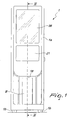
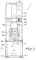
- the reference numeral 1 generally designates a machine for preparing and dispensing beverages, particularly hot and cold coffee-flavored beverages, shakes and the like.
- the machine 1 comprises a substantially box-shaped framework 1a, which rests on feet 1b and is internally associated with a contoured frame 1c for supporting the various components.
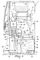
- the frame 1c supports at least one container 2 for storing a powdered soluble preparation for preparing a beverage, which is provided at the front with a discharge port 3, which is associated with dosage means 4 for dispensing a specific dose of preparation, and, in an upper region, with a loading port 5, which is closed by a removable lid 5a.
- the dosage means 4 shown schematically in Figure 3 since they are of a conventional type, comprise a screw feeder 6, which is accommodated inside the container 2, proximate to its bottom, and is rotationally actuated about its own longitudinal axis by an electric gear motor 7.
- the rotation of the screw feeder 6 causes the advancement of the preparation toward the discharge port 3.
- the preparation used in the machine 1 is of the type conventionally used to prepare beverages and can contain, for example, powdered coffee, pounded barley, powdered cocoa, freeze-dried milk, freeze-dried fruit, or a mixture of these ingredients.
- the machine 1 further has at least one tank 8 for collecting a liquid for dissolving the preparation, which is provided with a filling opening 9 and with a discharge opening 10 for said liquid, which is associated with pumping means 11 for drawing a specific amount of liquid from the inside of the tank 8.
- the liquid is water or milk or the like and is preferably kept inside the tank 8 at room temperature; however, alternative uses of the machine 1 in which the liquid in said tank is cooled or heated are not excluded.
- the tank 8 is accommodated in the lower portion of the framework 1a and is constituted by a tub 8a, which is open upward so as to form the filling opening 9, and by a lid 8b, which is arranged so as to rest on said tub and is provided with a through hole that forms the discharge opening 10.
- the lid 8b is fitted rigidly to the frame 1c by means of screws 12, and the tub 8a can be at least partially removed in order to introduce liquid after at least partially disassembling the front portion of the frame 1a.
- the tub 8a is in fact provided on the front wall with a knob 13 in order to facilitate its extraction during filling.
- the pumping means 11 are constituted by a conventional pump, in which the intake is connected to the tank 8 by means of the discharge opening 10; the machine 1 is provided with an intake duct 14, which is inserted in the discharge opening 10 and has a first end that draws from the bottom of the tub 8a and a second end that is opposite with respect to the first end and is associated with the intake of said pump.
- the delivery of the pump is instead associated with a delivery duct 15.
- the machine 1 further comprises at least one chamber 16, which is open in an upper region and is associated with, and connected to, the discharge port 3 and the discharge opening 10 in order to collect the dose of preparation and the amount of liquid fed respectively from the container 2 and from the tank 8, inside which means 17 for mixing the preparation and liquid to obtain the beverage are associated, and is provided with at least one dispensing opening 18 for the resulting beverage, which is associated with flow control means 19, which can move alternately between a configuration for opening said opening and for closing said opening ( Figure 3).
- the flow control means 19 are in the closed configuration when the mixing means 17 are operating, so as to keep the beverage in the vicinity of said mixing means.
- the resulting beverage can be whisked up as if it were blended or shaken in a conventional manner, since it remains for a chosen time in the vicinity of the mixing means 17.
- the served beverage therefore has a good consistency and a pleasant surface layer of froth.
- the delivery duct 15 leads into the chamber 16 so as to connect it to the discharge opening 10.
- the flow of the beverage through the chamber 16 occurs substantially in a downward vertical direction.
- the machine 1 is provided with a management and control unit 20, such as a conventional electronic board, which is not shown in detail and is functionally associated with the dosage means 4, with the pumping means 11, with the mixing means 17 and with the flow control means 19; the unit 20 is suitable to manage the automatic operation of the machine 1 and to time the sequential activation of the dosage means 4 and of the pumping means 11, of the mixing means 17 and finally of the flow control means 19.
- a management and control unit 20 such as a conventional electronic board, which is not shown in detail and is functionally associated with the dosage means 4, with the pumping means 11, with the mixing means 17 and with the flow control means 19; the unit 20 is suitable to manage the automatic operation of the machine 1 and to time the sequential activation of the dosage means 4 and of the pumping means 11, of the mixing means 17 and finally of the flow control means 19.
- the unit 20 is of the type that can be programmed by a user in order to set the intervention times of one or more of the dosage means 4, the pumping means 11, the mixing means 17, and the flow control means 19.
- the unit 20 is associated with user interface means, such as a keypad 21, which is not shown in detail and is arranged on the external front wall of the framework 1a and is provided for example with a button for starting an operating cycle for preparing a beverage, with a button for starting the washing cycle (which excludes the operation of the dosage means 4), and with a plurality of buttons or the like for adjusting the intervention times of said means.
- user interface means such as a keypad 21, which is not shown in detail and is arranged on the external front wall of the framework 1a and is provided for example with a button for starting an operating cycle for preparing a beverage, with a button for starting the washing cycle (which excludes the operation of the dosage means 4), and with a plurality of buttons or the like for adjusting the intervention times of said means.
- the intervention (opening) time of the flow control means 19 can, as an alternative, be fixed and at least equal to the value for which the chamber 16 is emptied.
- the unit 20 is further associated with a plurality of switches 22 for starting the operation of the machine 1, which are arranged inside the removable front portion of the framework 1a: a first general switch 22a for switching on and off said machine, a second switch 22b for actuating the pumping means 11 for filling the circuit, and a third switch 22c for actuating the opening of the flow control means 19 in order to evacuate residues of liquid or other matter in the chamber 16.
- switches 22 for starting the operation of the machine 1, which are arranged inside the removable front portion of the framework 1a: a first general switch 22a for switching on and off said machine, a second switch 22b for actuating the pumping means 11 for filling the circuit, and a third switch 22c for actuating the opening of the flow control means 19 in order to evacuate residues of liquid or other matter in the chamber 16.
- the mixing means 17 are arranged proximate to the bottom of the chamber 16; the dispensing opening 18 is arranged below said mixing means.
- the framework 1a protrudes so as to form a bracket 23 for supporting a cup B in which the beverage is served, and in which a removable tray 24 for collecting drops of beverage is inserted.
- the chamber 16 is constituted by a first portion 16a for receiving the dose of preparation and the amount of liquid fed respectively through the discharge port 3 and the discharge opening 10 and a second portion 16b, arranged below the first portion, for accommodating the mixing means 17, which is connected to the dispensing opening 18.
- the dispensing opening 18 is formed in the bottom of the second portion 16b, and the framework 1a is open at said dispensing opening.
- the first and second portions, respectively 16a and 16b, are mutually connected by means of an intermediate connecting portion 16c.
- the mixing means 17 comprise a rotating element, which is constituted by a shaft 25, which is supported by the second portion 16b so that it can rotate about its own longitudinal axis, and by a plurality of vanes 26, which are associated at a first end of said shaft that is supported in a cantilever fashion inside the second portion 16b.
- the shaft 25 is arranged horizontally and transversely with respect to the flow of the beverage along the second portion 16b, and has a second end, which is arranged opposite the first end and protrudes outside said second portion and is associated with motor means 27 for rotating it, sealing means being interposed between the shaft 25 and the wall of the second portion 16b in order to prevent any seepage of beverage.
- the flow control means 19 comprise a stem 28, which is arranged horizontally and transversely with respect to the flow of the beverage along the second portion 16b and is associated with means 29 for actuating its alternating translational motion between the open and closed configurations.
- the stem 28 is provided with an end for closing the dispensing opening 18, which is supported in a cantilever fashion inside the second portion 16b, and with an opposite end that protrudes outside said second portion and is associated with the actuation means 29, sealing means being interposed between the stem 28 and the wall of the second portion 16b in order to avoid any seepage of beverage.
- the flow control means 19 are provided with a membrane 30, which is associated with the closure end of the stem 28, said stem being suitable to produce the translational motion of the membrane 30 between the open configuration and the closed configuration.
- the membrane 30 allows to avoid any leakage of beverage in the closed configuration.
- the stem 28 has, at its closure end, a head that is contoured so as to form a shoulder for retaining the membrane 30.
- the membrane 30 is constituted by a sort of contoured hood made of substantially flexible material, which is fitted on the closure end of the stem 28 and is perimetrically coupled to the internal wall of the second portion 16b.
- the actuation means 29 may have, for example, an electromagnet that is associated with the stem 28 for actuating the translational motion from the closed configuration to the open configuration and cooperates with a compression contrast spring for returning said stem to the closed configuration.
- the machine 1 is provided with conventional means 31 for sensing when the liquid in the tank 8 is about to be depleted; said means are arranged below said tank and are substantially constituted by a microswitch, which cooperates with a compression contrast spring; the microswitch remains in the closed configuration until the weight of the liquid contained in the tank 8 is such as to overcome the reaction of the contrast spring, which is preloaded so as to trip the microswitch when the weight of the liquid drops below a threshold value for which it is convenient to perform a top-up.
- the sensing means 31 are associated with corresponding indicator means, such as a warning light or the like, not shown in the figures.
- the machine 1 can be provided with means 32 (schematically shown in dashed lines in Figure 3) for regulating the temperature of the amount of liquid drawn from the tank 8, so as to be able to serve hot or cold beverages while keeping the liquid inside said tank at room temperature.
- means 32 (schematically shown in dashed lines in Figure 3) for regulating the temperature of the amount of liquid drawn from the tank 8, so as to be able to serve hot or cold beverages while keeping the liquid inside said tank at room temperature.
- the temperature regulation means 32 may have heating means 33 arranged along the delivery duct 15 and preferably valve means 34 for flow control, which are interposed between said heating means and the chamber 16.
- the heating means 33 may be for example of the electrical (resistor-based) type.
- the machine 1 allows to obtain hot beverages, such as for example cappuccinos, that are entirely similar to those obtained with conventional bar machines with steam jets.
- the machine 1 can be equipped with a smart card reader 35 or the like for exchanging information regarding for example the status or the operation of the machine with the unit 20.
- the front wall of the framework 1a may have a transparent panel 36 bearing decorative patterns, advertising messages or others, associated with a corresponding light source 37 fitted inside said framework.
- the operation of the machine 1 is as follows: from the keypad 21, the user controls the activation of a work cycle, as set on the unit 20.
- the unit 20 activates in succession the operation of the dosage means 4 and the pumping means 11 for the set time, so as to send the intended dose of preparation and the intended amount of liquid into the chamber 16 and the operation of the motor means 27 so as to turn the rotating element for a chosen time, and finally activates the excitation of the electromagnet so as to cause the return of the stem 28 into the open configuration and serve the resulting beverage into the cup B arranged below the dispensing opening 18.
- the unit 20 interrupts the excitation of the electromagnet so as to return the stem 28 to the closed configuration by way of the action of the contrast spring.
- the described invention achieves the intended aim and objects, and in particular it achieves the aim of obtaining automatically a beverage that is entirely similar, in the appreciation of the customer, to those conventionally obtained with blenders, shakers or jets of steam.
Landscapes
- Physics & Mathematics (AREA)
- General Physics & Mathematics (AREA)
- Beverage Vending Machines With Cups, And Gas Or Electricity Vending Machines (AREA)
- Apparatus For Making Beverages (AREA)
Applications Claiming Priority (2)
| Application Number | Priority Date | Filing Date | Title |
|---|---|---|---|
| ITMO20040020 | 2004-01-29 | ||
| ITMO20040020 ITMO20040020A1 (it) | 2004-01-29 | 2004-01-29 | Macchina per la preparazione e l'erogazione di bevande |
Publications (2)
| Publication Number | Publication Date |
|---|---|
| EP1560174A2 true EP1560174A2 (fr) | 2005-08-03 |
| EP1560174A3 EP1560174A3 (fr) | 2005-10-19 |
Family
ID=34640383
Family Applications (1)
| Application Number | Title | Priority Date | Filing Date |
|---|---|---|---|
| EP05001097A Withdrawn EP1560174A3 (fr) | 2004-01-29 | 2005-01-20 | Dispositif de préparation et de distribution de boissons |
Country Status (2)
| Country | Link |
|---|---|
| EP (1) | EP1560174A3 (fr) |
| IT (1) | ITMO20040020A1 (fr) |
Family Cites Families (7)
| Publication number | Priority date | Publication date | Assignee | Title |
|---|---|---|---|---|
| IT1089070B (it) * | 1977-12-01 | 1985-06-10 | Grossi Lucio | Macchina automatica per la preparazione di bevande calde impiegante prodotti liofilizzati o solubili,quali caffe',cioccolato o simili |
| US5538749A (en) * | 1993-07-09 | 1996-07-23 | H. J. Heinz Company | Apparatus, soup concentrate and process for dispensing soup |
| US5927553A (en) * | 1996-07-24 | 1999-07-27 | Bunn-O-Matic Coporation | Powdered beverage mixing and dispensing apparatus |
| US5975357A (en) * | 1996-12-24 | 1999-11-02 | Topar; William M. | Beverage dispensing apparatus having consistent mix delivery of beverage to container |
| JP3032787B1 (ja) * | 1999-04-12 | 2000-04-17 | 一誠 生田 | 具入りス―プ類の小分け装置 |
| US6513421B2 (en) * | 2000-10-04 | 2003-02-04 | Kazumasa Ikuta | Subdividing apparatus for ingredients-contained soup |
| US6698228B2 (en) * | 2001-11-02 | 2004-03-02 | Moobella, Llc | Method and apparatus for producing and dispensing an aerated and/or blended food product |
-
2004
- 2004-01-29 IT ITMO20040020 patent/ITMO20040020A1/it unknown
-
2005
- 2005-01-20 EP EP05001097A patent/EP1560174A3/fr not_active Withdrawn
Also Published As
| Publication number | Publication date |
|---|---|
| ITMO20040020A1 (it) | 2004-04-29 |
| EP1560174A3 (fr) | 2005-10-19 |
Similar Documents
| Publication | Publication Date | Title |
|---|---|---|
| CN105030070B (zh) | 饮品烹制装置及方法 | |
| JP2791276B2 (ja) | 飲物の抽出及び分配機械 | |
| US8733234B2 (en) | Appliance for conditioning a milk-based liquid | |
| CN100405960C (zh) | 饮料制造装置 | |
| CN103442581B (zh) | 饮品烹制装置及方法 | |
| JP5450152B2 (ja) | 飲料製造装置 | |
| CN102859559B (zh) | 用于分配饮料配料的集成方法和系统 | |
| CN103096770B (zh) | 调配机和分配系统及相关方法 | |
| US20100024657A9 (en) | Machine for brewing a beverage such as coffee and related method | |
| JP2005040605A (ja) | 温飲料機 | |
| MX2011006111A (es) | Metodo y sistema integrados para suministrar y batir/mezclar ingredientes de bebida. | |
| US9890027B2 (en) | Beverage supply apparatus with touch panel control | |
| JP5537987B2 (ja) | ミルクフォーマー及び飲料製造装置 | |
| JP6546393B2 (ja) | 飲料供給装置 | |
| JP4397341B2 (ja) | ミルクフォーマー | |
| JP5338509B2 (ja) | カップ式飲料自動販売機 | |
| EP1560174A2 (fr) | Dispositif de préparation et de distribution de boissons | |
| JP2011167396A (ja) | 飲料製造装置 | |
| JP5595752B2 (ja) | 飲料製造装置 | |
| JP2011167395A (ja) | 飲料製造装置 | |
| JP2017202101A (ja) | カップ式自動販売機およびカップ式自動販売機の攪拌具 | |
| HK1187210B (en) | Brewed beverage appliance and method | |
| HK1158913B (en) | Appliance for conditioning a milk-based liquid | |
| JPH0636777B2 (ja) | 飲料抽出装置 |
Legal Events
| Date | Code | Title | Description |
|---|---|---|---|
| PUAI | Public reference made under article 153(3) epc to a published international application that has entered the european phase |
Free format text: ORIGINAL CODE: 0009012 |
|
| AK | Designated contracting states |
Kind code of ref document: A2 Designated state(s): AT BE BG CH CY CZ DE DK EE ES FI FR GB GR HU IE IS IT LI LT LU MC NL PL PT RO SE SI SK TR |
|
| AX | Request for extension of the european patent |
Extension state: AL BA HR LV MK YU |
|
| PUAL | Search report despatched |
Free format text: ORIGINAL CODE: 0009013 |
|
| AK | Designated contracting states |
Kind code of ref document: A3 Designated state(s): AT BE BG CH CY CZ DE DK EE ES FI FR GB GR HU IE IS IT LI LT LU MC NL PL PT RO SE SI SK TR |
|
| AX | Request for extension of the european patent |
Extension state: AL BA HR LV MK YU |
|
| 17P | Request for examination filed |
Effective date: 20060221 |
|
| AKX | Designation fees paid |
Designated state(s): ES IT |
|
| REG | Reference to a national code |
Ref country code: DE Ref legal event code: 8566 |
|
| STAA | Information on the status of an ep patent application or granted ep patent |
Free format text: STATUS: THE APPLICATION HAS BEEN WITHDRAWN |
|
| 17Q | First examination report despatched |
Effective date: 20080519 |
|
| 18W | Application withdrawn |
Effective date: 20080523 |