EP1560247A2 - Procédé pour la fabrication d'une lampe électrique et lampe électrique - Google Patents
Procédé pour la fabrication d'une lampe électrique et lampe électrique Download PDFInfo
- Publication number
- EP1560247A2 EP1560247A2 EP04025947A EP04025947A EP1560247A2 EP 1560247 A2 EP1560247 A2 EP 1560247A2 EP 04025947 A EP04025947 A EP 04025947A EP 04025947 A EP04025947 A EP 04025947A EP 1560247 A2 EP1560247 A2 EP 1560247A2
- Authority
- EP
- European Patent Office
- Prior art keywords
- lamp
- glass
- lamp vessel
- metal composite
- power supply
- Prior art date
- Legal status (The legal status is an assumption and is not a legal conclusion. Google has not performed a legal analysis and makes no representation as to the accuracy of the status listed.)
- Withdrawn
Links
Images


Classifications
-
- H—ELECTRICITY
- H01—ELECTRIC ELEMENTS
- H01K—ELECTRIC INCANDESCENT LAMPS
- H01K3/00—Apparatus or processes adapted to the manufacture, installing, removal, or maintenance of incandescent lamps or parts thereof
- H01K3/02—Manufacture of incandescent bodies
-
- H—ELECTRICITY
- H01—ELECTRIC ELEMENTS
- H01K—ELECTRIC INCANDESCENT LAMPS
- H01K3/00—Apparatus or processes adapted to the manufacture, installing, removal, or maintenance of incandescent lamps or parts thereof
- H01K3/12—Joining of mount or stem to vessel; Joining parts of the vessel, e.g. by butt sealing
-
- H—ELECTRICITY
- H01—ELECTRIC ELEMENTS
- H01K—ELECTRIC INCANDESCENT LAMPS
- H01K1/00—Details
- H01K1/36—Seals between parts of vessel, e.g. between stem and envelope
Definitions
- the invention relates to a method for producing an electrical according to the Preamble of claim 1 and an electric lamp.
- the inventive manufacturing method for electric lamps is characterized characterized in that during the manufacturing process, a prefabricated, as a lamp vessel seal serving glass-metal composite is provided from the Projecting power supply for at least one bulb, wherein during a the first step, the at least one lamp with its power supply is connected, and during one, the first process step downstream second method step, the lamp vessel via the at least one Illuminant is slipped and connected to the glass-metal composite.
- the lamp vessel and serving as a lamp vessel sealing glass-metal composite are preferably fused together for bonding to one another To ensure thermally highly resilient, gas-tight connection.
- the merging the two aforementioned components is preferably carried out by means of LASER, the locally limited heating of the lamp vessel and the glass-metal composite in the connection area allows, so that the embedding of the power supply lines in the glass-metal composite is not affected by the heating becomes.
- at least the connection region between the two aforementioned Lamp parts subjected to a heat treatment are preferably fused together for bonding to one another.
- connection to the lamp vessel which is usually an axisymmetric or rotationally symmetrical hollow body is to be able to produce
- one end of the glass-metal composite provided with a tubular approach.
- the dimensions of this tubular approach transverse to the lamp axis are preferably on the corresponding Dimensions of the lamp vessel matched.
- the connection area between the lamp vessel and the glass-metal composite should be as possible have a large distance to the at least one light source to disrupt the To largely exclude light emission by stray light.
- the connection area between the lamp vessel and the glass-metal composite should therefore possible arranged close to the lamp base or even hidden in the lamp base become.
- inventive method in combination with a Applicable glass-metal composite, which is made of a glass tube by be passed through the glass tube, the metallic power supply and then a portion of the glass tube is softened by heating and the Power supplies embedded by squeezing the softened glass in the glass become.
- a lamp vessel sealing glass-metal composite already optimally adapted to the geometry of the lamp vessel.
- tube-like approach which serves to connect to the lamp vessel, not manufactured separately, but is due to the geometry of the glass tube already exists.
- the manufacturing method of the invention offers particularly great advantages in the Production of electric lamps, their lamps with respect to a lamp base or a lamp base part serving as a reference.
- the adjustment of the at least one Light source with respect to the lamp base advantageously already during its installation performed on its power supply lines.
- the lamp vessel and its lamp vessel sealing provided with the power supply designed as separate components, the only after the alignment and Assembly of the at least one lamp to be fused together so that the at least one lamp and the ends of its power supply for the adjustment and installation of at least one light source remain accessible.
- the Adjustment of the at least one luminous means with respect to the lamp cap becomes more advantageous Way thus immediately during the assembly of the at least one Bulb performed on its power supplies.
- This will be the comparatively complex 5-axis adjustment according to the above-cited prior Technology superfluous.
- This reference level can therefore also for the exact Alignment of the at least one light source in an optical system, be used for example in a headlight.
- At least one Bulbs are in the case of an incandescent lamp around a filament and in Case of a gas discharge lamp around the electrodes of the lamp, between which during the lamp operation, the gas discharge is formed.
- the electric lamp according to the invention has at least one light-emitting means which is enclosed by a lamp vessel, wherein the lamp vessel with a lamp vessel seal is provided by the power supply lines for the at least a light source are passed.
- the lamp vessel and the lamp vessel seal formed as a separate lamp components by Connecting means are joined together.
- the lamp vessel sealing is advantageously designed as a pinch seal, preferably either a metal foil embedding in quartz glass or a metal wire embedding in tempered glass, wherein the embedded in the quartz glass Metal foils or embedded in the hard glass metal wires part of the Power supplies are.
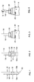
- FIGS. 1 to 7 illustrate the production method according to the invention the production of a halogen incandescent lamp for a motor vehicle headlight.
- FIG. 1 shows the structure of the power supply lines 1, 2 of the halogen incandescent lamp.
- the power supply lines 1, 2 of the halogen incandescent lamp are made of a U-shaped Molybdenum wire 10, two molybdenum foils 11, 12 and two other straight molybdenum wires 13, 14 of different lengths.
- the two ends of the U-shaped Molybdenum wire 10 are each with one of the two molybdenum foils 11th or 12 welded.
- one end of the metal wires 13, 14 is with one of the two Molybdenum foils 11 and 12 welded.
- the two straight metal wires 13, 14 form the inside of the lamp vessel extending inner part of the power supply lines 1 and 2, while the two legs of the U-shaped metal wire 10th the outside of the lamp vessel extending outer part of the power supply lines 1 or 2 form.
- the connection between the two U-legs 10a, 10b of the U-shaped Molybdenum wire 10 is separated before the base of the lamp, the means that the curved connection area is removed by means of a cutting tool.
- the illustrated in Figure 1, consisting of the two power supply lines 1, 2 existing Frame is inserted into a quartz glass tube, leaving the free ends of the two Straight molybdenum wires 13, 14 protrude from the one end of the quartz glass tube and the U-shaped molybdenum wire from the other end of the quartz glass tube protrudes.
- the quartz glass tube is in the range of molybdenum foils 11, 12 on his Softening heated and squeezed by squeezing the softened Quartz glass to the molybdenum foils 11, 12 pressed to a gas-tight seal of the molybdenum foils 11, 12 in the quartz glass.
- glass-metal composite 3 serves as Lampengefäßabdichtung.
- the molybdenum foils 11, 12 are in the sealing region 30 of the glass-metal composite 3 embedded gas-tight.
- the two molybdenum wires 13, 14 protrude from the tubular projection 31 of the glass-metal composite 3 out.
- the U-shaped molybdenum wire 10 protrudes out of the sealing area 30. Since that from the power supply 1, 2 existing frame now through the quartz glass of the glass-metal composite 3 is completely fixed and has sufficient mechanical stability, For example, as discussed above, the U-shaped molybdenum wire 10 may now be be be separated.
- the sealing region 30 of the glass-metal composite shown in FIG 3 is then in the prefabricated lamp base 4 of Halogen incandescent lamp introduced and fixed by means of clamping fit ( Figure 3).
- the lamp base 4 has three in a common plane reference tabs 41, the extend perpendicular to the lamp axis A-A and equidistant along the circumference of the lamp cap 4 are arranged. Define these reference tabs 41 a reference plane for the adjustment of the filament 5. For adjusting and mounting the Filament 5 are then the free ends of the molybdenum wires 13, 14th shaped so that the filament 5 after welding their ends with the Ends of the molybdenum wires 13, 14 is axially aligned. When welding the Incandescent filament 5 with the ends of the molybdenum wires 13, 14 is the position of the filament adjusted with respect to the reference tabs 41 within predetermined tolerances ( Figure 4).
- the lamp vessel 5 is circular cylindrical formed, has an open first end and a second end, from the a pumping stem 61 protrudes.
- the lamp vessel 6 was also a quartz glass tube used which has the same inner and outer diameter like the quartz glass tube from which the glass-metal composite 3 was made.
- To the assembly of the filament 5 is the illustrated in Figure 5, prefabricated cylindrical and hood-like lamp vessel 6 on the filament 5 and the power supply lines slipped so that the open first end of the lamp vessel 6 on the tubular approach 31 of the glass-metal composite 3 is seated.
- the open first end of the prefabricated lamp vessel 6, the same inner and outer diameter as the tube-like projection 31 of the glass-metal composite 3, is by means of a laser with the tubular extension 31 of the glass-metal composite 3 merged.
- FIG. 8 schematically shows a first alternative embodiment of a glass-metal composite 3 ', instead of the shown in Figure 2 glass-metal composite 3 used as a lamp vessel seal for the lamp vessel 6 can be.
- the glass-metal composite 3 'shown in FIG. 8 differs from FIG the illustrated in Figure 2 glass-metal composite 3 only in that the tubular Neck 31 'is flared conically. In all other features, the glass-metal composite is right 3 'with the glass-metal composite 3 match. Therefore, in the Figures 2 and 8 for identical components and the same reference numerals.
- a quartz glass tube is used, the has a smaller inner and outer diameter than the lamp vessel 6.
- This glass-metal composite 3 ' has opposite the glass-metal composite 3 the advantage that the junction, that is, the bead 62 closer to Sealing area 30 'and thus closer to the lamp base 4 and at a greater distance to the filament 5 is arranged as when using the illustrated in Figure 2 Glass-metal composite 3. This reduces the light scattering at the bead 62.
- the light scattering at the bead 62 can also be achieved by means of a light-absorbing Coating the bead 62 or by hiding the bead 62 inside of the lamp cap 4 can be prevented.
- the bead 62 in the Be arranged portion of the top of the lamp envelope so that the bead 62 through the light-absorbing coating is covered.
- the hood-like Lamp vessel 6 only from the provided with the pumping stem 61 dome and the tube-like projection 31 envelops the filament 5 and forms almost the entire cylindrical part of the lamp bulb.
- FIG. 9 shows a second alternative embodiment of a glass-metal composite 9, instead of the glass-metal composite 3 shown in FIG Lamp vessel seal is usable.
- This glass-metal composite 9 consists of two molybdenum wires 91, 92, the gas-tight in a tempered glass, for example aluminosilicate glass or borosilicate glass, embedded so that both ends of each molybdenum wire 91, 92 protrude from the hard glass.
- a tempered glass for example aluminosilicate glass or borosilicate glass
- this glass-metal composite 9 For the production of this glass-metal composite 9, the two molybdenum wires 91, 92 through a hard glass tube threaded through and the hard glass tube in the sealing region 93 to its softening temperature heated by means of squeezing the softened hard glass to the Molybdenum wires 91, 92 to press. After cooling the glass are the molybdenum wires 91, 92 gas-tight in the sealing region 93 embedded.
- the glass-metal composite 9 has at one end a conically widened, tubular extension 94 on, which is provided for fusing with the lamp vessel 6. This glass-metal composite 9 lends itself to lamps whose lamp vessel sealing during the lamp operation only a comparatively low thermal load is exposed.
- Lamp vessel seals become the glass-metal composites shown in FIGS. 2 or 8 3, 3 'used in quartz glass.
- the lamp vessel seals 3, 3 'and 9 can each be both with a quartz glass lamp vessel 6 as well be fused with a lamp vessel made of toughened glass.
- the choice of the glass for the lamp vessel 6 and serving as a lamp vessel sealing glass-metal composite 3, 3 '9 depends on the thermal load of the lamp vessel and the lamp vessel sealing during lamp operation.
- the invention is not limited to the exemplary embodiments explained in greater detail above. but, for example, to other lamp types, for example Discharge lamps are applied.
- Discharge lamps are applied.
- evacuating the Lamp vessel and the introduction of the filling components in the lamp vessel dispensed with a pumping stems if these manufacturing steps, for example be performed in the interior of a glove box under a protective gas atmosphere.
Landscapes
- Engineering & Computer Science (AREA)
- Manufacturing & Machinery (AREA)
- Vessels And Coating Films For Discharge Lamps (AREA)
- Non-Portable Lighting Devices Or Systems Thereof (AREA)
Applications Claiming Priority (2)
| Application Number | Priority Date | Filing Date | Title |
|---|---|---|---|
| DE10355101 | 2003-11-24 | ||
| DE10355101A DE10355101A1 (de) | 2003-11-24 | 2003-11-24 | Verfahren zur Herstellung einer elektrischen Lampe und elektrische Lampe |
Publications (2)
| Publication Number | Publication Date |
|---|---|
| EP1560247A2 true EP1560247A2 (fr) | 2005-08-03 |
| EP1560247A3 EP1560247A3 (fr) | 2008-03-05 |
Family
ID=34530305
Family Applications (1)
| Application Number | Title | Priority Date | Filing Date |
|---|---|---|---|
| EP04025947A Withdrawn EP1560247A3 (fr) | 2003-11-24 | 2004-11-02 | Procédé pour la fabrication d'une lampe électrique et lampe électrique |
Country Status (6)
| Country | Link |
|---|---|
| US (1) | US20050110413A1 (fr) |
| EP (1) | EP1560247A3 (fr) |
| JP (1) | JP2005158733A (fr) |
| KR (1) | KR20050050037A (fr) |
| CN (1) | CN1652294A (fr) |
| DE (1) | DE10355101A1 (fr) |
Families Citing this family (1)
| Publication number | Priority date | Publication date | Assignee | Title |
|---|---|---|---|---|
| JP4893352B2 (ja) * | 2007-02-15 | 2012-03-07 | ウシオ電機株式会社 | 白熱電球 |
Family Cites Families (9)
| Publication number | Priority date | Publication date | Assignee | Title |
|---|---|---|---|---|
| US2162546A (en) * | 1934-07-09 | 1939-06-13 | Gen Electric | Gaseous electric discharge device |
| US4052638A (en) * | 1976-02-27 | 1977-10-04 | General Electric Company | Flare-wedge lamp |
| GB1592508A (en) * | 1976-12-07 | 1981-07-08 | Tokyo Shibaura Electric Co | Method for manufacturing a luminous tube for discharge lamp |
| DE9017224U1 (de) * | 1990-12-20 | 1991-03-07 | Patent-Treuhand-Gesellschaft für elektrische Glühlampen mbH, 8000 München | Kittlos gesockelte elektrische Lampe |
| EP0609477B1 (fr) * | 1993-02-05 | 1999-05-06 | Patent-Treuhand-Gesellschaft für elektrische Glühlampen mbH | Enceinte céramique à décharge pour lampe à décharge à haute pression et sa méthode de fabrication et matériau d'étanchéité associé |
| US5818154A (en) * | 1994-08-10 | 1998-10-06 | Patent-Treuhand-Gesellschaft Fur Elektrische Gluhlampen Mbh | Halogen incandescent lamp in cementless base |
| PL331013A1 (en) * | 1997-05-06 | 1999-06-21 | Koninkl Philips Electronics Nv | Cap-tyre electric bulb |
| US6140769A (en) * | 1997-05-06 | 2000-10-31 | U.S. Philips Corporation | Electric incandescent lamp with sintered body glass plate |
| US6641449B2 (en) * | 2001-04-24 | 2003-11-04 | Osram Sylvania Inc. | High pressure lamp bulb and method of induction sealing |
-
2003
- 2003-11-24 DE DE10355101A patent/DE10355101A1/de not_active Withdrawn
-
2004
- 2004-11-02 EP EP04025947A patent/EP1560247A3/fr not_active Withdrawn
- 2004-11-12 JP JP2004329669A patent/JP2005158733A/ja not_active Withdrawn
- 2004-11-17 US US10/992,256 patent/US20050110413A1/en not_active Abandoned
- 2004-11-23 KR KR1020040096249A patent/KR20050050037A/ko not_active Withdrawn
- 2004-11-24 CN CNA2004100758773A patent/CN1652294A/zh active Pending
Also Published As
| Publication number | Publication date |
|---|---|
| JP2005158733A (ja) | 2005-06-16 |
| US20050110413A1 (en) | 2005-05-26 |
| DE10355101A1 (de) | 2005-06-02 |
| KR20050050037A (ko) | 2005-05-27 |
| CN1652294A (zh) | 2005-08-10 |
| EP1560247A3 (fr) | 2008-03-05 |
Similar Documents
| Publication | Publication Date | Title |
|---|---|---|
| DE3112878A1 (de) | Quecksilberdampf-niederdruckentladungslampe und verfahren zur herstellung | |
| DE1043502B (de) | Elektrische Lampe mit einem Glaskolben und nach aussen vorspringendem flachem Glasquetschfuss | |
| DE687262C (de) | Verfahren zur Herstellung von zweisockeligen elektrischen Gluehlampen | |
| EP0239006A2 (fr) | Lampe à incandescence à halogène et son procédé de fabrication | |
| EP0910867B1 (fr) | Procede de production d'une lampe a incandescence electrique | |
| DE69405181T2 (de) | Hochdruck-Entladungslampe | |
| DE3127461A1 (de) | Gluehfadenhalterung und elektrische verbindung fuer eine halogenlampe sowie herstellungsverfahren | |
| DE2118061B2 (de) | Verfahren zur Herstellung von Glühlampen | |
| DE3112821A1 (de) | Elektrische lampe mit einer als quetschung ausgebildeten gefaesseinschmelzung sowie vorrichtung und verfahren zur herstellung | |
| EP2020678A2 (fr) | Lampe électrique dotée d'un piston extérieur et d'une lampe intégrée agencée dans le piston extérieur | |
| DE69110097T2 (de) | Elektrische Glühlampe. | |
| DE60028321T2 (de) | Elektrische glühlampe | |
| EP2510537B1 (fr) | Lampe à incandescence halogène pour phare de véhicule | |
| EP1560247A2 (fr) | Procédé pour la fabrication d'une lampe électrique et lampe électrique | |
| DE3035786A1 (de) | Gluehlampe | |
| EP0219860B1 (fr) | Méthode de fabrication d'une lampe à décharge à haute pression à halogénures de métal à pincement unique et une lampe fabriquée suivant cette méthode | |
| WO2001001437A1 (fr) | Procede pour culotter une lampe electrique | |
| EP0588201A2 (fr) | Lampe à décharge haute pression et procédé pour la fabrication d'une lampe à décharge à haute pression | |
| EP2465134B1 (fr) | Ampoule halogène pour phare de véhicule | |
| DE2841347A1 (de) | Zweifadenhalogengluehlampe | |
| DE2420342A1 (de) | Halogengluehlampe und verfahren zur herstellung | |
| DE3125192A1 (de) | Halogengluehlampe | |
| EP0219861A2 (fr) | Méthode de fabrication d'une lampe à décharge à haute pression à halogénures de métal à pincement unique et une lampe fabriquée suivant cette méthode | |
| DE2909259A1 (de) | Wolfram-halogen-lampe fuer einen monoblock-scheinwerfer sowie methode zu ihrer herstellung | |
| DE102018201068B4 (de) | Glühlampe für fahrzeugscheinwerfer und herstellungsverfahren |
Legal Events
| Date | Code | Title | Description |
|---|---|---|---|
| PUAI | Public reference made under article 153(3) epc to a published international application that has entered the european phase |
Free format text: ORIGINAL CODE: 0009012 |
|
| AK | Designated contracting states |
Kind code of ref document: A2 Designated state(s): AT BE BG CH CY CZ DE DK EE ES FI FR GB GR HU IE IS IT LI LU MC NL PL PT RO SE SI SK TR |
|
| AX | Request for extension of the european patent |
Extension state: AL HR LT LV MK YU |
|
| PUAL | Search report despatched |
Free format text: ORIGINAL CODE: 0009013 |
|
| AK | Designated contracting states |
Kind code of ref document: A3 Designated state(s): AT BE BG CH CY CZ DE DK EE ES FI FR GB GR HU IE IS IT LI LU MC NL PL PT RO SE SI SK TR |
|
| AX | Request for extension of the european patent |
Extension state: AL HR LT LV MK YU |
|
| AKX | Designation fees paid | ||
| STAA | Information on the status of an ep patent application or granted ep patent |
Free format text: STATUS: THE APPLICATION IS DEEMED TO BE WITHDRAWN |
|
| 18D | Application deemed to be withdrawn |
Effective date: 20080906 |
|
| REG | Reference to a national code |
Ref country code: DE Ref legal event code: 8566 |