EP1560253B1 - Appareil destiné au revêtement de substrats, l'appareil comprenant un sorbeur - Google Patents
Appareil destiné au revêtement de substrats, l'appareil comprenant un sorbeur Download PDFInfo
- Publication number
- EP1560253B1 EP1560253B1 EP20050000927 EP05000927A EP1560253B1 EP 1560253 B1 EP1560253 B1 EP 1560253B1 EP 20050000927 EP20050000927 EP 20050000927 EP 05000927 A EP05000927 A EP 05000927A EP 1560253 B1 EP1560253 B1 EP 1560253B1
- Authority
- EP
- European Patent Office
- Prior art keywords
- compartment
- cathode
- array
- substrate
- absorber
- Prior art date
- Legal status (The legal status is an assumption and is not a legal conclusion. Google has not performed a legal analysis and makes no representation as to the accuracy of the status listed.)
- Ceased
Links
- 239000000758 substrate Substances 0.000 title claims description 28
- 238000000576 coating method Methods 0.000 title claims description 24
- 239000011248 coating agent Substances 0.000 title claims description 21
- 238000005247 gettering Methods 0.000 title claims description 5
- 229910052751 metal Inorganic materials 0.000 claims description 30
- 239000007789 gas Substances 0.000 claims description 28
- 239000002184 metal Substances 0.000 claims description 27
- 239000006096 absorbing agent Substances 0.000 claims description 26
- 239000000463 material Substances 0.000 claims description 3
- 239000002826 coolant Substances 0.000 claims description 2
- 229910052729 chemical element Inorganic materials 0.000 claims 1
- 239000011261 inert gas Substances 0.000 claims 1
- QVGXLLKOCUKJST-UHFFFAOYSA-N atomic oxygen Chemical compound [O] QVGXLLKOCUKJST-UHFFFAOYSA-N 0.000 description 23
- 239000001301 oxygen Substances 0.000 description 23
- 229910052760 oxygen Inorganic materials 0.000 description 23
- 229910044991 metal oxide Inorganic materials 0.000 description 13
- 150000004706 metal oxides Chemical class 0.000 description 13
- IJGRMHOSHXDMSA-UHFFFAOYSA-N Atomic nitrogen Chemical compound N#N IJGRMHOSHXDMSA-UHFFFAOYSA-N 0.000 description 8
- 238000000034 method Methods 0.000 description 5
- XKRFYHLGVUSROY-UHFFFAOYSA-N Argon Chemical compound [Ar] XKRFYHLGVUSROY-UHFFFAOYSA-N 0.000 description 4
- XLOMVQKBTHCTTD-UHFFFAOYSA-N Zinc monoxide Chemical compound [Zn]=O XLOMVQKBTHCTTD-UHFFFAOYSA-N 0.000 description 4
- 150000004767 nitrides Chemical class 0.000 description 4
- 229910052757 nitrogen Inorganic materials 0.000 description 4
- 238000004544 sputter deposition Methods 0.000 description 4
- 239000010936 titanium Substances 0.000 description 4
- 230000000694 effects Effects 0.000 description 3
- 150000002739 metals Chemical class 0.000 description 3
- 238000000926 separation method Methods 0.000 description 3
- 239000013077 target material Substances 0.000 description 3
- RTAQQCXQSZGOHL-UHFFFAOYSA-N Titanium Chemical compound [Ti] RTAQQCXQSZGOHL-UHFFFAOYSA-N 0.000 description 2
- 238000010521 absorption reaction Methods 0.000 description 2
- 229910052786 argon Inorganic materials 0.000 description 2
- 238000011109 contamination Methods 0.000 description 2
- 238000000151 deposition Methods 0.000 description 2
- 230000008021 deposition Effects 0.000 description 2
- 238000011161 development Methods 0.000 description 2
- 230000018109 developmental process Effects 0.000 description 2
- 238000010586 diagram Methods 0.000 description 2
- 239000010408 film Substances 0.000 description 2
- 239000011521 glass Substances 0.000 description 2
- VNWKTOKETHGBQD-UHFFFAOYSA-N methane Chemical compound C VNWKTOKETHGBQD-UHFFFAOYSA-N 0.000 description 2
- 230000003287 optical effect Effects 0.000 description 2
- 239000002245 particle Substances 0.000 description 2
- 239000010409 thin film Substances 0.000 description 2
- 229910052719 titanium Inorganic materials 0.000 description 2
- 239000011787 zinc oxide Substances 0.000 description 2
- 239000004215 Carbon black (E152) Substances 0.000 description 1
- 229910052776 Thorium Inorganic materials 0.000 description 1
- GWEVSGVZZGPLCZ-UHFFFAOYSA-N Titan oxide Chemical compound O=[Ti]=O GWEVSGVZZGPLCZ-UHFFFAOYSA-N 0.000 description 1
- 229910007667 ZnOx Inorganic materials 0.000 description 1
- 229910052782 aluminium Inorganic materials 0.000 description 1
- XAGFODPZIPBFFR-UHFFFAOYSA-N aluminium Chemical compound [Al] XAGFODPZIPBFFR-UHFFFAOYSA-N 0.000 description 1
- 238000006243 chemical reaction Methods 0.000 description 1
- 239000002131 composite material Substances 0.000 description 1
- 150000001875 compounds Chemical class 0.000 description 1
- 238000010924 continuous production Methods 0.000 description 1
- 239000000110 cooling liquid Substances 0.000 description 1
- PMHQVHHXPFUNSP-UHFFFAOYSA-M copper(1+);methylsulfanylmethane;bromide Chemical compound Br[Cu].CSC PMHQVHHXPFUNSP-UHFFFAOYSA-M 0.000 description 1
- 230000007423 decrease Effects 0.000 description 1
- 230000003247 decreasing effect Effects 0.000 description 1
- 238000009792 diffusion process Methods 0.000 description 1
- 230000009977 dual effect Effects 0.000 description 1
- 239000005357 flat glass Substances 0.000 description 1
- 229930195733 hydrocarbon Natural products 0.000 description 1
- 150000002430 hydrocarbons Chemical class 0.000 description 1
- 238000004519 manufacturing process Methods 0.000 description 1
- 238000006396 nitration reaction Methods 0.000 description 1
- QGLKJKCYBOYXKC-UHFFFAOYSA-N nonaoxidotritungsten Chemical compound O=[W]1(=O)O[W](=O)(=O)O[W](=O)(=O)O1 QGLKJKCYBOYXKC-UHFFFAOYSA-N 0.000 description 1
- 125000004430 oxygen atom Chemical group O* 0.000 description 1
- 238000005192 partition Methods 0.000 description 1
- 230000008092 positive effect Effects 0.000 description 1
- 239000002244 precipitate Substances 0.000 description 1
- 239000012495 reaction gas Substances 0.000 description 1
- 230000009257 reactivity Effects 0.000 description 1
- 230000037072 sun protection Effects 0.000 description 1
- 229910052715 tantalum Inorganic materials 0.000 description 1
- XOLBLPGZBRYERU-UHFFFAOYSA-N tin dioxide Chemical compound O=[Sn]=O XOLBLPGZBRYERU-UHFFFAOYSA-N 0.000 description 1
- 229910001887 tin oxide Inorganic materials 0.000 description 1
- OGIDPMRJRNCKJF-UHFFFAOYSA-N titanium oxide Inorganic materials [Ti]=O OGIDPMRJRNCKJF-UHFFFAOYSA-N 0.000 description 1
- 229910001930 tungsten oxide Inorganic materials 0.000 description 1
- 229910052726 zirconium Inorganic materials 0.000 description 1
Images

Classifications
-
- H—ELECTRICITY
- H01—ELECTRIC ELEMENTS
- H01J—ELECTRIC DISCHARGE TUBES OR DISCHARGE LAMPS
- H01J37/00—Discharge tubes with provision for introducing objects or material to be exposed to the discharge, e.g. for the purpose of examination or processing thereof
- H01J37/32—Gas-filled discharge tubes
- H01J37/32431—Constructional details of the reactor
- H01J37/32798—Further details of plasma apparatus not provided for in groups H01J37/3244 - H01J37/32788; special provisions for cleaning or maintenance of the apparatus
- H01J37/32853—Hygiene
- H01J37/32871—Means for trapping or directing unwanted particles
-
- C—CHEMISTRY; METALLURGY
- C23—COATING METALLIC MATERIAL; COATING MATERIAL WITH METALLIC MATERIAL; CHEMICAL SURFACE TREATMENT; DIFFUSION TREATMENT OF METALLIC MATERIAL; COATING BY VACUUM EVAPORATION, BY SPUTTERING, BY ION IMPLANTATION OR BY CHEMICAL VAPOUR DEPOSITION, IN GENERAL; INHIBITING CORROSION OF METALLIC MATERIAL OR INCRUSTATION IN GENERAL
- C23C—COATING METALLIC MATERIAL; COATING MATERIAL WITH METALLIC MATERIAL; SURFACE TREATMENT OF METALLIC MATERIAL BY DIFFUSION INTO THE SURFACE, BY CHEMICAL CONVERSION OR SUBSTITUTION; COATING BY VACUUM EVAPORATION, BY SPUTTERING, BY ION IMPLANTATION OR BY CHEMICAL VAPOUR DEPOSITION, IN GENERAL
- C23C14/00—Coating by vacuum evaporation, by sputtering or by ion implantation of the coating forming material
- C23C14/0021—Reactive sputtering or evaporation
- C23C14/0036—Reactive sputtering
- C23C14/0063—Reactive sputtering characterised by means for introducing or removing gases
-
- C—CHEMISTRY; METALLURGY
- C23—COATING METALLIC MATERIAL; COATING MATERIAL WITH METALLIC MATERIAL; CHEMICAL SURFACE TREATMENT; DIFFUSION TREATMENT OF METALLIC MATERIAL; COATING BY VACUUM EVAPORATION, BY SPUTTERING, BY ION IMPLANTATION OR BY CHEMICAL VAPOUR DEPOSITION, IN GENERAL; INHIBITING CORROSION OF METALLIC MATERIAL OR INCRUSTATION IN GENERAL
- C23C—COATING METALLIC MATERIAL; COATING MATERIAL WITH METALLIC MATERIAL; SURFACE TREATMENT OF METALLIC MATERIAL BY DIFFUSION INTO THE SURFACE, BY CHEMICAL CONVERSION OR SUBSTITUTION; COATING BY VACUUM EVAPORATION, BY SPUTTERING, BY ION IMPLANTATION OR BY CHEMICAL VAPOUR DEPOSITION, IN GENERAL
- C23C14/00—Coating by vacuum evaporation, by sputtering or by ion implantation of the coating forming material
- C23C14/22—Coating by vacuum evaporation, by sputtering or by ion implantation of the coating forming material characterised by the process of coating
- C23C14/56—Apparatus specially adapted for continuous coating; Arrangements for maintaining the vacuum, e.g. vacuum locks
- C23C14/562—Apparatus specially adapted for continuous coating; Arrangements for maintaining the vacuum, e.g. vacuum locks for coating elongated substrates
-
- C—CHEMISTRY; METALLURGY
- C23—COATING METALLIC MATERIAL; COATING MATERIAL WITH METALLIC MATERIAL; CHEMICAL SURFACE TREATMENT; DIFFUSION TREATMENT OF METALLIC MATERIAL; COATING BY VACUUM EVAPORATION, BY SPUTTERING, BY ION IMPLANTATION OR BY CHEMICAL VAPOUR DEPOSITION, IN GENERAL; INHIBITING CORROSION OF METALLIC MATERIAL OR INCRUSTATION IN GENERAL
- C23C—COATING METALLIC MATERIAL; COATING MATERIAL WITH METALLIC MATERIAL; SURFACE TREATMENT OF METALLIC MATERIAL BY DIFFUSION INTO THE SURFACE, BY CHEMICAL CONVERSION OR SUBSTITUTION; COATING BY VACUUM EVAPORATION, BY SPUTTERING, BY ION IMPLANTATION OR BY CHEMICAL VAPOUR DEPOSITION, IN GENERAL
- C23C14/00—Coating by vacuum evaporation, by sputtering or by ion implantation of the coating forming material
- C23C14/22—Coating by vacuum evaporation, by sputtering or by ion implantation of the coating forming material characterised by the process of coating
- C23C14/56—Apparatus specially adapted for continuous coating; Arrangements for maintaining the vacuum, e.g. vacuum locks
- C23C14/564—Means for minimising impurities in the coating chamber such as dust, moisture, residual gases
Definitions
- the invention relates to a device for coating a substrate with an absorber arrangement according to the preamble of claim 1.
- each of the two cathodes being in their own Section of a plurality of adjacently arranged, together forming a vacuum chamber, is provided over a passage interconnected compartments.
- a method of forming a low-emissivity layer on a glass substrate by first applying a reflective metal layer and then a metal oxide layer to the substrate in the presence of an oxygen absorber.
- an oxygen absorber a hydrocarbon such as methane is preferably used.
- the metal oxide layer may consist, for example, of tin oxide, zinc oxide, tungsten oxide or other metal oxides.
- the DD 214 865 A1 discloses a method and apparatus for producing layer systems on flat glass by plasma atomizing.
- metal and metal oxide layers are to be applied in an alternating sequence in a continuous process.
- Argon is introduced into the metallic coating chamber and sucked out of the oxidic chamber after flowing through it.
- the argon pressure in the metallic chamber is above the partial pressure in the oxidic chamber.
- the reaction gas is selectively sucked between the chambers.
- the US 2001 // 015173 A1 discloses an apparatus for forming thin films on a metal substrate. Independent targets formed of at least two metals are deposited by sputtering to form an ultra-thin film of a composite metal. The ultrathin film is treated with a reactive gas. The steps are repeated several times until a film of desired thickness is formed.
- the invention is therefore based on the object to provide a device for coating a substrate, in which the coating of the substrate with metal and metal oxides in the same device can take place in spatial proximity to each other.
- an absorber arrangement is present in at least one of the compartments which contains the free oxygen or any other reactive gas, such as, for example, Receiving nitrogen, so that the substrate, which is carried out under the absorber arrangement, in the following or in front of subjects z. B. can be provided with a metal layer whose quality is not reduced by oxygen, nitrogen or other reactive gas.
- the absorber arrangement in this case has a cathode arrangement which acts as a getter cathode, by continuously generating in the absorber arrangement a metal layer which is available for reaction with the reactive gas.
- the absorber arrangement comprises a plurality of plate-shaped metal elements to increase the surface.
- a screen between the plate-shaped metal elements and the substrate is used to increase the reactive surface.
- the device is cooled by the plate-shaped metal elements, for example, flows through a cooling liquid.
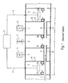
- FIG. 1 shows, for a better understanding of the measures according to the invention, first in a schematic sectional view, an exemplary embodiment of a device 1 for coating a substrate 2 according to the prior art in a lateral overall view.
- Such a device 1 is for coating a substrate 2 such as e.g. Glass with various coatings, e.g. Heat protection layers or sun protection layers.
- a substrate 2 such as e.g. Glass
- various coatings e.g. Heat protection layers or sun protection layers.
- the device 1 comprises a vacuum main chamber 3, which is divided into a plurality of compartments 4 to 8, wherein all compartments 4 to 8 via a passage formed by means of shafts 26, 27 passage 9, 10 communicate with each other and individual compartments 4 and 8 are each equipped with a sputtering cathode 11, 12, wherein the two cathodes 11, 12 via supply lines 13, 14, for example are connected to an AC power source 15, for example a medium frequency generator.
- the second, third and fourth compartments 5, 6, 7 are in the embodiment respectively connected to a separate vacuum pump 16, 17, 18, e.g. a turbo pump, connected, wherein the two compartments 4, 5 and 7, 8 are interconnected via openings 19, 20 in the respective partitions 21, 22.
- the compartments 4, 6 and 8 are connected in the illustrated embodiment to gas supply lines 23, 23a, 24, 24a, 25 and 25a, via which process gas or via the gas supply lines 24 and 24a reactive gas in the individual compartments 4 to 8 can be admitted.
- the reactive gas can also be supplied in the cathode compartments.
- the substrate 2 is transported during the coating process along the passage 9, 10 or through the shafts 26, 27 and moved past the cathodes 11, 12.
- a problem of the described vacuum chamber 3 is the connection of the individual compartments 4 to 8 with each other.
- the connection is unavoidable because the to be coated Substrate 2 on all subjects 4 to 8 must be passed to apply the desired coating can.
- the reactive gas atmosphere in this case the oxygen atmosphere, which is introduced into the corresponding compartment 4 to 8 for the coating with a metal oxide .
- With reduced partial pressure can also penetrate those compartments in which a coating with the metal should take place.
- oxygen penetrates there is a risk that the metal coating undesirably partially oxidizes and changes properties.
- a device 1 according to FIGS. 2 to 4 in contrast, has an absorber arrangement 34 for the active deposition of the reactive gas by gettering with a cathode arrangement 37, whereby it is possible to carry out different coatings in closely adjacent compartments of the device 1, which have different reactive gas requirements. As a result, reactive and non-reactive atmospheres can be generated in spatially closely adjacent compartments.
- the device 1 can thus have a considerably shorter overall length, which has a positive effect on the costs of both the provision and the operation.
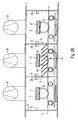
- FIG. 2A shows in a highly schematic representation the basic structure of a device 1 designed according to the invention. At least one compartment 5 with a double cathode 30 is formed Cathode arrangement 37 provided. The compartment 5 is separated by walls 31 from adjacent compartments 4 and 6. The walls 31 may be cooled for reasons explained in more detail below.
- the dual cathode 30 has two targets 39 which, for example, consist of aluminum Al or titanium Ti.
- targets 39 which, for example, consist of aluminum Al or titanium Ti.
- Other suitable target materials are e.g. the elements Ta, Th and Zr.
- plasma clouds 33 are formed during operation of the cathode assembly.
- Between the walls 31 of the compartment 5 are in the embodiment perpendicular to the substrate 2 and parallel to the walls 31 plate-shaped elements 34 a, for example made of metal sheets, which divide the compartment 5 into individual areas 35 and form the absorber assembly 34.
- the optimum shape and arrangement of the plate-shaped elements 34a is determined by the consideration that as few particles of the reactive gas can diffuse past the absorber arrangement 34.
- plate-shaped elements 34a in an inclined position makes sense, since thereby the available effective area for gettering is greater than in accordance with the invention perpendicular plate-shaped elements 34a.
- the target materials must be chosen so that on the one hand a very good getter effect is achieved and on the other hand, related optical properties to the previous coating are present so it does not to material technical incompatibilities comes.
- Al over a ZnAl oxide layer or Ti over a titanium layer should be used to build a titanium oxide gradient.
- Incompatibilities of the materials can be expressed, for example, in optical absorption, layer adhesion problems or particle diffusion.
- compartment 4 in an oxidic atmosphere and compartment 6 in a non-oxidic, e.g. Sputtered nitridic atmosphere there is a risk in conventional devices 1 of the transfer of oxygen into the nitridic atmosphere, with the result of contamination of the metal nitride layer.
- This is counteracted by the development of the invention characterized in that the diffusing from the tray 4 oxygen atoms in the intermediate tray 5 on the elements 34a of the absorber assembly 34, which is always coated with a metal layer with high affinity for oxygen through the cathode assembly 37, react to metal oxides and so absorbed.
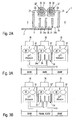
- FIGS. 3A and 3B show in a highly schematic manner the mode of operation of the absorber arrangement 34 with the cathode arrangement 37 according to FIG. 2A.
- FIG. 3A firstly shows the situation when the double cathode 30 is switched off, while FIG. 3B shows the mode of operation with the double cathode 30 switched on.
- compartment 4 there is a certain oxygen partial pressure, which corresponds to a reactive gas flow of, for example, about 250 sccm, for sputtering Without further measures, the oxygen diffuses into the adjacent compartments, so that in compartment 6, where a metal layer is to be sputtered, there is still an oxygen partial pressure corresponding to a reactive gas flow of about 100 sccm, which determines the quality of the metal coating would severely affect.
- the oxygen concentration in compartment 6 can be based on a reactive gas flow be reduced by about 25 sccm, which is only one tenth compared to the Re15gasfluß in compartment 4. Without switched double cathode 30 is still four times the reactive gas flow in compartment 6 before.
- the oxygen flowing out of the compartment 4 reacts with the metal layer on the plate-shaped elements 34a of the absorber arrangement 34 and precipitates as metal oxide on the elements 34a in compartment 5.
- the reactive gas flow in compartment 5 decreases, so that less oxygen can flow into the next compartment 6.
- the same can also be realized for nitrogen and other reactive gases with the corresponding target materials.
- the plate-shaped elements 34a are preferably as well as the walls 31 cooled by the plate-shaped elements 34a are formed, for example, double-walled and flowed through by a coolant. This increases and stabilizes the reactivity of the surfaces.
- the elements 34a are preferably sandblasted before assembly in order to have a high degree of roughness.
- a screen 34b shown in Fig. 2A for example, arranged from a metal wire mesh.
- the plates can, as already mentioned above, be arranged inclined or labyrinthine and provided with holes or slots. The more plate-shaped elements 34a are present, the larger the surface available for absorbing, and thus the better the active gas separation.
- FIG. 4 shows in a highly schematized manner an overall overview of a device 1 designed according to the invention.
- the substrate 2 first passes through a number of empty compartments and is then provided by means of corresponding targets 32 in several successive compartments, for example with a metal oxide or nitride layer. Thereafter, in the compartment designated AST, the active gas separation takes place by means of the absorber arrangement 34 and the cathode assembly 37, not shown. In the next compartment can then be started immediately with the sputtering, for example, a metal layer without a significant contamination with reactive gas occurs.
- metal, metal oxide and metal nitride layers may be deposited, e.g. Zinc oxide ZnOx next to aluminum nitride AlN.
- FIG. 5A shows the signal of the oxygen sensor in compartment 6 and the oxygen partial pressure as a function of the amount of compartment 4 in FIG 5B shows the oxygen balance in compartment 6 at constant gas inlet in compartment 4 and varied power of the cathode arrangement 37 in compartment 5.
- FIG. 5A shows the signal of the oxygen sensor in compartment 6 and the oxygen partial pressure as a function of the amount of compartment 4 in FIG 5B shows the oxygen balance in compartment 6 at constant gas inlet in compartment 4 and varied power of the cathode arrangement 37 in compartment 5.
- Clearly visible is the increasing absorption or gettering effect of the cathode arrangement 37, as shown by a decreasing oxygen partial pressure in compartment 6.
- a saturation value is reached, beyond which a further increase in performance causes no appreciable reduction of the oxygen partial pressure in compartment 6 anymore.
- the invention is not limited to the illustrated embodiment. In particular, other spatial configurations are possible.
Landscapes
- Chemical & Material Sciences (AREA)
- Engineering & Computer Science (AREA)
- Organic Chemistry (AREA)
- Materials Engineering (AREA)
- Mechanical Engineering (AREA)
- Metallurgy (AREA)
- Chemical Kinetics & Catalysis (AREA)
- Health & Medical Sciences (AREA)
- Epidemiology (AREA)
- Public Health (AREA)
- Physics & Mathematics (AREA)
- Plasma & Fusion (AREA)
- Analytical Chemistry (AREA)
- Physical Vapour Deposition (AREA)
Claims (9)
- Dispositif (1) pour le revêtement d'un substrat (2), comprenant une chambre à vide (3), laquelle est divisée par des parois (31) en plusieurs compartiments (4 - 8),
dans lequel au moins un ensemble de cathodes (32) est disposé dans au moins un des compartiments (4 - 8),
dans lequel au moins un compartiment (5) présente un ensemble absorbeur (34) et au moins un ensemble de cathodes (37) pour le dégazage,
dans lequel au moins un compartiment (4) voisin du compartiment (5) pourvu de l'ensemble de cathodes (37) et de l'ensemble absorbeur (34) présente des conduites d'amenée de gaz (23, 23a) servant à la production d'une atmosphère oxydante ou nitrurante, caractérisé en ce que l'ensemble absorbeur (34) présente une pluralité d'éléments en forme de plaques (34a), qui sont disposés entre les parois (31) du compartiment (5) et partagent le compartiment (5) en zones individuelles (35), et qui sont disposés parallèlement aux parois (31) du compartiment (5) et perpendiculairement au substrat (2) et en ce qu'un tamis (34b) est disposé entre les éléments en forme de plaques (34a) et le substrat (2). - Dispositif selon la revendication 1, caractérisé en ce que l'ensemble absorbeur (34) est en métal.
- Dispositif selon la revendication 1 ou 2, caractérisé en ce que l'ensemble absorbeur (34) est sablé.
- Dispositif selon l'une quelconque des revendications 1 à 3, caractérisé en ce que l'ensemble absorbeur (34) est réalisé de sorte à pouvoir être traversé par un produit réfrigérant.
- Dispositif selon l'une quelconque des revendications 1 à 4, caractérisé en ce que le nombre d'éléments en forme de plaques (34a) est variable.
- Dispositif selon l'une quelconque des revendications 1 à 5, caractérisé en ce que l'ensemble de cathodes (37) est réalisé sous forme de double cathode (30).
- Dispositif selon l'une quelconque des revendications 1 à 6, caractérisé en ce que l'ensemble de cathodes (37) est réalisé de sorte à pouvoir être exploité avec une tension située dans la plage allant de 550 V à 700 V et/ou une puissance située dans la plage allant de 50 kW à 100 kW.
- Dispositif selon l'une quelconque des revendications 1 à 7, caractérisé en ce que l'ensemble de cathodes (37) comporte au moins une cible (39), dont le matériau contient les éléments chimiques A1 et/ou Ti et/ou Zr et/ou Ta et/ou Th.
- Dispositif selon l'une quelconque des revendications 1 à 8, caractérisé en ce qu'au moins un compartiment (6) voisin du compartiment (5) muni de la cathode à getter (37) présente des conduites d'amenée de gaz (25, 25a) permettant de produire une atmosphère de gaz protecteur.
Applications Claiming Priority (2)
| Application Number | Priority Date | Filing Date | Title |
|---|---|---|---|
| DE200410004844 DE102004004844B4 (de) | 2004-01-30 | 2004-01-30 | Vorrichtung zum Beschichten eines Substrats mit einer Absorberanordnung |
| DE102004004844 | 2004-01-30 |
Publications (3)
| Publication Number | Publication Date |
|---|---|
| EP1560253A2 EP1560253A2 (fr) | 2005-08-03 |
| EP1560253A3 EP1560253A3 (fr) | 2006-06-14 |
| EP1560253B1 true EP1560253B1 (fr) | 2007-10-17 |
Family
ID=34638816
Family Applications (1)
| Application Number | Title | Priority Date | Filing Date |
|---|---|---|---|
| EP20050000927 Ceased EP1560253B1 (fr) | 2004-01-30 | 2005-01-18 | Appareil destiné au revêtement de substrats, l'appareil comprenant un sorbeur |
Country Status (2)
| Country | Link |
|---|---|
| EP (1) | EP1560253B1 (fr) |
| DE (2) | DE102004004844B4 (fr) |
Families Citing this family (1)
| Publication number | Priority date | Publication date | Assignee | Title |
|---|---|---|---|---|
| DE102015117450B4 (de) * | 2015-10-14 | 2024-11-07 | VON ARDENNE Asset GmbH & Co. KG | Prozessieranordnung und Transportanordnung |
Family Cites Families (8)
| Publication number | Priority date | Publication date | Assignee | Title |
|---|---|---|---|---|
| DE203335C (fr) * | ||||
| JPS4917623B1 (fr) | 1969-09-22 | 1974-05-02 | ||
| DD203335A1 (de) * | 1981-12-30 | 1983-10-19 | Ullrich Heisig | Verfahren und einrichtung zum vakuumbeschichten durch plasmatronzerstaeuben |
| DD214865A1 (de) * | 1983-05-04 | 1984-10-24 | Fi M V Ardenne Dresden | Verfahren und einrichtung zur herstellung von schichtsystemen auf flachglas |
| JPH0718423A (ja) * | 1993-07-06 | 1995-01-20 | Japan Energy Corp | 薄膜形成装置 |
| US6361618B1 (en) * | 1994-07-20 | 2002-03-26 | Applied Materials, Inc. | Methods and apparatus for forming and maintaining high vacuum environments |
| JP3735461B2 (ja) * | 1998-03-27 | 2006-01-18 | 株式会社シンクロン | 複合金属の化合物薄膜形成方法及びその薄膜形成装置 |
| DZ3047A1 (fr) * | 1999-05-27 | 2004-03-27 | Pfizer Prod Inc | Sel mutuel d'amlopidine et d'atorvastatine, procédé pour sa préparation et compositions pharmaceutiques les contenant. |
-
2004
- 2004-01-30 DE DE200410004844 patent/DE102004004844B4/de not_active Expired - Lifetime
-
2005
- 2005-01-18 EP EP20050000927 patent/EP1560253B1/fr not_active Ceased
- 2005-01-18 DE DE200550001694 patent/DE502005001694D1/de not_active Expired - Lifetime
Also Published As
| Publication number | Publication date |
|---|---|
| EP1560253A2 (fr) | 2005-08-03 |
| EP1560253A3 (fr) | 2006-06-14 |
| DE102004004844A1 (de) | 2005-08-25 |
| DE102004004844B4 (de) | 2009-04-09 |
| DE502005001694D1 (de) | 2007-11-29 |
Similar Documents
| Publication | Publication Date | Title |
|---|---|---|
| EP2521804B1 (fr) | Installation de revêtement en ligne | |
| DE4341173B4 (de) | Vorrichtung und Verfahren zur Abscheidung unterschiedlicher Materialien auf einem Substrat | |
| DE3317349C2 (fr) | ||
| DE3815006A1 (de) | Vorrichtung zum herstellen von beschichtungen mit abgestufter zusammensetzung | |
| WO2006010451A2 (fr) | Installation de revetement sous vide et procede de revetement sous vide | |
| DE3938830C2 (fr) | ||
| EP1626433B1 (fr) | Appareillage de pulvérisation magnétron, cathode cylindrique et méthod de depot des multicouches minces sur un substrat | |
| DE102004005313A1 (de) | Verfahren zur Herstellung eines Ultrabarriere-Schichtsystems | |
| WO2012010339A1 (fr) | Procédé et ensemble pour produire des couches supraconductrices sur des substrats | |
| DE102005058869A1 (de) | Verfahren und Vorrichtung zur Beschichtung von Bändern | |
| AT501722B1 (de) | Beschichtungsverfahren | |
| EP2872665B1 (fr) | Procédé de revêtement par impulsion haute puissance | |
| DE102004021734B4 (de) | Verfahren und Vorrichtung zur kontinuierlichen Beschichtung flacher Substrate mit optisch aktiven Schichtsystemen | |
| DE102012109691B4 (de) | Solarabsorber-Schichtsystem mit Gradientenschicht und Verfahren zu dessen Herstellung | |
| EP1693905B1 (fr) | Procédé de préparation de revêtements à orientation biaxiale | |
| DE102004014323B4 (de) | Verfahren und Anordnung zur Herstellung von Gradientenschichten oder Schichtenfolgen durch physikalische Vakuumzerstäubung | |
| EP1673488B1 (fr) | Dispositif modulaire de revêtement de surfaces | |
| EP1560253B1 (fr) | Appareil destiné au revêtement de substrats, l'appareil comprenant un sorbeur | |
| WO2011151057A1 (fr) | Procédé et dispositif de séparation de gaz réactifs dans des installations de revêtement en ligne | |
| DE102010002839A1 (de) | Beschichtungsanlage und Verfahren zur Beschichtung von Halbleiterscheiben in Beschichtungsanlagen | |
| DE69215077T2 (de) | Verfahren und Vorrichtung zum Erzeugen von Dünnschichten | |
| EP3417086B1 (fr) | Dispositif et procédé d'élaboration de propriétés définies de couches à gradient d'un système de revêtement multicouche dans le cas d'installations de pulvérisation cathodique | |
| EP2699705B1 (fr) | Procédé de dépôt d'un système de revêtement de barrière transparente | |
| DE10143145C1 (de) | Verfahren und Einrichtung zur Herstellung von Schichtsystemen für optische Präzisionselemente | |
| EP1520290B1 (fr) | Dispositif de revetement de substrats par separation physique de vapeur par l'effet de cathode creuse |
Legal Events
| Date | Code | Title | Description |
|---|---|---|---|
| PUAI | Public reference made under article 153(3) epc to a published international application that has entered the european phase |
Free format text: ORIGINAL CODE: 0009012 |
|
| AK | Designated contracting states |
Kind code of ref document: A2 Designated state(s): AT BE BG CH CY CZ DE DK EE ES FI FR GB GR HU IE IS IT LI LT LU MC NL PL PT RO SE SI SK TR |
|
| AX | Request for extension of the european patent |
Extension state: AL BA HR LV MK YU |
|
| PUAL | Search report despatched |
Free format text: ORIGINAL CODE: 0009013 |
|
| AK | Designated contracting states |
Kind code of ref document: A3 Designated state(s): AT BE BG CH CY CZ DE DK EE ES FI FR GB GR HU IE IS IT LI LT LU MC NL PL PT RO SE SI SK TR |
|
| AX | Request for extension of the european patent |
Extension state: AL BA HR LV MK YU |
|
| RIC1 | Information provided on ipc code assigned before grant |
Ipc: C23C 14/56 20060101ALI20060505BHEP Ipc: C23C 14/00 20060101AFI20060505BHEP Ipc: H01J 37/32 20060101ALI20060505BHEP |
|
| 17P | Request for examination filed |
Effective date: 20060628 |
|
| 17Q | First examination report despatched |
Effective date: 20060727 |
|
| 17Q | First examination report despatched |
Effective date: 20060727 |
|
| AKX | Designation fees paid |
Designated state(s): DE FR GB |
|
| GRAP | Despatch of communication of intention to grant a patent |
Free format text: ORIGINAL CODE: EPIDOSNIGR1 |
|
| GRAS | Grant fee paid |
Free format text: ORIGINAL CODE: EPIDOSNIGR3 |
|
| GRAA | (expected) grant |
Free format text: ORIGINAL CODE: 0009210 |
|
| AK | Designated contracting states |
Kind code of ref document: B1 Designated state(s): DE FR GB |
|
| REG | Reference to a national code |
Ref country code: GB Ref legal event code: FG4D Free format text: NOT ENGLISH |
|
| GBT | Gb: translation of ep patent filed (gb section 77(6)(a)/1977) |
Effective date: 20071017 |
|
| REF | Corresponds to: |
Ref document number: 502005001694 Country of ref document: DE Date of ref document: 20071129 Kind code of ref document: P |
|
| ET | Fr: translation filed | ||
| PLBE | No opposition filed within time limit |
Free format text: ORIGINAL CODE: 0009261 |
|
| STAA | Information on the status of an ep patent application or granted ep patent |
Free format text: STATUS: NO OPPOSITION FILED WITHIN TIME LIMIT |
|
| 26N | No opposition filed |
Effective date: 20080718 |
|
| REG | Reference to a national code |
Ref country code: FR Ref legal event code: PLFP Year of fee payment: 11 |
|
| REG | Reference to a national code |
Ref country code: FR Ref legal event code: PLFP Year of fee payment: 12 |
|
| REG | Reference to a national code |
Ref country code: FR Ref legal event code: PLFP Year of fee payment: 13 |
|
| REG | Reference to a national code |
Ref country code: FR Ref legal event code: PLFP Year of fee payment: 14 |
|
| PGFP | Annual fee paid to national office [announced via postgrant information from national office to epo] |
Ref country code: FR Payment date: 20230123 Year of fee payment: 19 |
|
| PGFP | Annual fee paid to national office [announced via postgrant information from national office to epo] |
Ref country code: GB Payment date: 20230124 Year of fee payment: 19 Ref country code: DE Payment date: 20230126 Year of fee payment: 19 |
|
| REG | Reference to a national code |
Ref country code: DE Ref legal event code: R119 Ref document number: 502005001694 Country of ref document: DE |
|
| GBPC | Gb: european patent ceased through non-payment of renewal fee |
Effective date: 20240118 |
|
| PG25 | Lapsed in a contracting state [announced via postgrant information from national office to epo] |
Ref country code: DE Free format text: LAPSE BECAUSE OF NON-PAYMENT OF DUE FEES Effective date: 20240801 |
|
| PG25 | Lapsed in a contracting state [announced via postgrant information from national office to epo] |
Ref country code: GB Free format text: LAPSE BECAUSE OF NON-PAYMENT OF DUE FEES Effective date: 20240118 |
|
| PG25 | Lapsed in a contracting state [announced via postgrant information from national office to epo] |
Ref country code: FR Free format text: LAPSE BECAUSE OF NON-PAYMENT OF DUE FEES Effective date: 20240131 |
|
| PG25 | Lapsed in a contracting state [announced via postgrant information from national office to epo] |
Ref country code: GB Free format text: LAPSE BECAUSE OF NON-PAYMENT OF DUE FEES Effective date: 20240118 Ref country code: FR Free format text: LAPSE BECAUSE OF NON-PAYMENT OF DUE FEES Effective date: 20240131 Ref country code: DE Free format text: LAPSE BECAUSE OF NON-PAYMENT OF DUE FEES Effective date: 20240801 |