EP1560309A2 - Zündkerze mit hohen Isolationseigenschaften und hoher Zündungsfähigkeit des Luft-Brennstoffgemisches. - Google Patents
Zündkerze mit hohen Isolationseigenschaften und hoher Zündungsfähigkeit des Luft-Brennstoffgemisches. Download PDFInfo
- Publication number
- EP1560309A2 EP1560309A2 EP05001732A EP05001732A EP1560309A2 EP 1560309 A2 EP1560309 A2 EP 1560309A2 EP 05001732 A EP05001732 A EP 05001732A EP 05001732 A EP05001732 A EP 05001732A EP 1560309 A2 EP1560309 A2 EP 1560309A2
- Authority
- EP
- European Patent Office
- Prior art keywords
- insulator
- spark plug
- reference plane
- metal shell
- outer diameter
- Prior art date
- Legal status (The legal status is an assumption and is not a legal conclusion. Google has not performed a legal analysis and makes no representation as to the accuracy of the status listed.)
- Withdrawn
Links
- 238000009413 insulation Methods 0.000 title abstract description 62
- 239000000446 fuel Substances 0.000 title description 3
- 239000000203 mixture Substances 0.000 title description 2
- 239000012212 insulator Substances 0.000 claims abstract description 161
- 229910052751 metal Inorganic materials 0.000 claims abstract description 100
- 239000002184 metal Substances 0.000 claims abstract description 100
- 229910000510 noble metal Inorganic materials 0.000 claims description 40
- 229910045601 alloy Inorganic materials 0.000 claims description 18
- 239000000956 alloy Substances 0.000 claims description 18
- 239000000654 additive Substances 0.000 claims description 16
- 230000000996 additive effect Effects 0.000 claims description 16
- 229910052759 nickel Inorganic materials 0.000 claims description 9
- 229910052721 tungsten Inorganic materials 0.000 claims description 9
- 238000002844 melting Methods 0.000 claims description 8
- 230000008018 melting Effects 0.000 claims description 8
- 229910052763 palladium Inorganic materials 0.000 claims description 8
- 229910052702 rhenium Inorganic materials 0.000 claims description 8
- 229910052703 rhodium Inorganic materials 0.000 claims description 8
- 229910052707 ruthenium Inorganic materials 0.000 claims description 8
- PNEYBMLMFCGWSK-UHFFFAOYSA-N aluminium oxide Inorganic materials [O-2].[O-2].[O-2].[Al+3].[Al+3] PNEYBMLMFCGWSK-UHFFFAOYSA-N 0.000 claims description 7
- 238000007789 sealing Methods 0.000 claims description 7
- 229910052593 corundum Inorganic materials 0.000 claims description 5
- 229910001845 yogo sapphire Inorganic materials 0.000 claims description 5
- RUDFQVOCFDJEEF-UHFFFAOYSA-N yttrium(III) oxide Inorganic materials [O-2].[O-2].[O-2].[Y+3].[Y+3] RUDFQVOCFDJEEF-UHFFFAOYSA-N 0.000 claims description 5
- 229910052782 aluminium Inorganic materials 0.000 claims description 4
- 229910052741 iridium Inorganic materials 0.000 claims description 4
- 229910052697 platinum Inorganic materials 0.000 claims description 3
- 238000011835 investigation Methods 0.000 abstract description 15
- 239000003570 air Substances 0.000 description 38
- OKTJSMMVPCPJKN-UHFFFAOYSA-N Carbon Chemical compound [C] OKTJSMMVPCPJKN-UHFFFAOYSA-N 0.000 description 23
- 229910052799 carbon Inorganic materials 0.000 description 23
- 238000002485 combustion reaction Methods 0.000 description 10
- BASFCYQUMIYNBI-UHFFFAOYSA-N platinum Substances [Pt] BASFCYQUMIYNBI-UHFFFAOYSA-N 0.000 description 10
- PXHVJJICTQNCMI-UHFFFAOYSA-N nickel Substances [Ni] PXHVJJICTQNCMI-UHFFFAOYSA-N 0.000 description 9
- 238000012360 testing method Methods 0.000 description 8
- KDLHZDBZIXYQEI-UHFFFAOYSA-N palladium Substances [Pd] KDLHZDBZIXYQEI-UHFFFAOYSA-N 0.000 description 6
- 238000003466 welding Methods 0.000 description 6
- 239000000463 material Substances 0.000 description 5
- 239000010948 rhodium Substances 0.000 description 5
- 238000010835 comparative analysis Methods 0.000 description 4
- 230000000694 effects Effects 0.000 description 3
- 238000005259 measurement Methods 0.000 description 3
- 239000007769 metal material Substances 0.000 description 3
- XEEYBQQBJWHFJM-UHFFFAOYSA-N Iron Chemical compound [Fe] XEEYBQQBJWHFJM-UHFFFAOYSA-N 0.000 description 2
- 230000007423 decrease Effects 0.000 description 2
- 239000011521 glass Substances 0.000 description 2
- 238000012986 modification Methods 0.000 description 2
- 230000004048 modification Effects 0.000 description 2
- 239000003566 sealing material Substances 0.000 description 2
- XLYOFNOQVPJJNP-UHFFFAOYSA-N water Substances O XLYOFNOQVPJJNP-UHFFFAOYSA-N 0.000 description 2
- 229910001209 Low-carbon steel Inorganic materials 0.000 description 1
- KJTLSVCANCCWHF-UHFFFAOYSA-N Ruthenium Chemical compound [Ru] KJTLSVCANCCWHF-UHFFFAOYSA-N 0.000 description 1
- 230000001133 acceleration Effects 0.000 description 1
- 239000000853 adhesive Substances 0.000 description 1
- 230000001070 adhesive effect Effects 0.000 description 1
- XAGFODPZIPBFFR-UHFFFAOYSA-N aluminium Chemical compound [Al] XAGFODPZIPBFFR-UHFFFAOYSA-N 0.000 description 1
- 239000012080 ambient air Substances 0.000 description 1
- 230000006835 compression Effects 0.000 description 1
- 238000007906 compression Methods 0.000 description 1
- 238000010276 construction Methods 0.000 description 1
- 238000001816 cooling Methods 0.000 description 1
- 239000011162 core material Substances 0.000 description 1
- 230000007797 corrosion Effects 0.000 description 1
- 238000005260 corrosion Methods 0.000 description 1
- 230000003247 decreasing effect Effects 0.000 description 1
- 238000009434 installation Methods 0.000 description 1
- GKOZUEZYRPOHIO-UHFFFAOYSA-N iridium atom Chemical compound [Ir] GKOZUEZYRPOHIO-UHFFFAOYSA-N 0.000 description 1
- 229910052742 iron Inorganic materials 0.000 description 1
- WUAPFZMCVAUBPE-UHFFFAOYSA-N rhenium atom Chemical compound [Re] WUAPFZMCVAUBPE-UHFFFAOYSA-N 0.000 description 1
- MHOVAHRLVXNVSD-UHFFFAOYSA-N rhodium atom Chemical compound [Rh] MHOVAHRLVXNVSD-UHFFFAOYSA-N 0.000 description 1
- 239000000454 talc Substances 0.000 description 1
- 229910052623 talc Inorganic materials 0.000 description 1
- WFKWXMTUELFFGS-UHFFFAOYSA-N tungsten Chemical compound [W] WFKWXMTUELFFGS-UHFFFAOYSA-N 0.000 description 1
- 239000010937 tungsten Substances 0.000 description 1
- 229910052727 yttrium Inorganic materials 0.000 description 1
- VWQVUPCCIRVNHF-UHFFFAOYSA-N yttrium atom Chemical compound [Y] VWQVUPCCIRVNHF-UHFFFAOYSA-N 0.000 description 1
Images


Classifications
-
- H—ELECTRICITY
- H01—ELECTRIC ELEMENTS
- H01T—SPARK GAPS; OVERVOLTAGE ARRESTERS USING SPARK GAPS; SPARKING PLUGS; CORONA DEVICES; GENERATING IONS TO BE INTRODUCED INTO NON-ENCLOSED GASES
- H01T13/00—Sparking plugs
- H01T13/20—Sparking plugs characterised by features of the electrodes or insulation
- H01T13/39—Selection of materials for electrodes
-
- H—ELECTRICITY
- H01—ELECTRIC ELEMENTS
- H01T—SPARK GAPS; OVERVOLTAGE ARRESTERS USING SPARK GAPS; SPARKING PLUGS; CORONA DEVICES; GENERATING IONS TO BE INTRODUCED INTO NON-ENCLOSED GASES
- H01T13/00—Sparking plugs
- H01T13/20—Sparking plugs characterised by features of the electrodes or insulation
- H01T13/38—Selection of materials for insulation
Definitions
- the present invention relates generally to spark plugs for internal combustion engines. More particularly, the invention relates to a spark plug with an improved structure in which a metal shell has a threaded portion with an outer diameter of 12 mm or less.
- the improved structure ensures the spark plug of high insulation properties and a high capability to ignite the air-fuel mixture (referred to as ignition capability hereinafter).
- Conventional spark plugs for use in internal combustion engines generally include a tubular metal shell, an insulator, a center electrode, and a ground electrode.
- the metal shell has a threaded portion for fitting the spark plug into a combustion chamber of the engine.
- the insulator has a center bore formed therein and is fixed in the metal shell such that an end thereof protrudes from an end of the metal shell.
- the center electrode is so secured in the center bore of the insulator that an end thereof protrudes from the end of the insulator.
- the ground electrode has a tip portion and is joined to the end of the metal shell such that the tip portion faces the end of the center electrode through a spark gap therebetween.
- the threaded portion of the metal shell in a spark plug had an outer diameter of M 14 as specified in JIS (Japanese Industrial Standards) in the past; however, the threaded portion is now required to have an outer diameter of M 12 or less as specified in JIS.
- JIS Japanese Industrial Standards
- the volume of an air pocket which is the insulation space between an outer surface of the insulator and an inner surface of the metal shell, is accordingly reduced.
- the insulator generally includes an intermediate portion and an end portion that includes the end of the insulator protruding from the metal shell.
- the end portion is thinner than the intermediate portion, and there is provided a frusto-conical shoulder between the two portions.
- the shoulder engages with an annular seat of the metal shell, which is formed on the inner surface of the metal shell, through a gasket so as to establish a gas-tight seal. Accordingly, the air pocket formed in the spark plug has a range in the lengthwise direction of the insulator from the end of the metal shell to the place where the shoulder of the insulator and the annular seat of the metal shell are in sealing engagement.
- inside sparks can be generated instead of normal sparks to be generated in the spark gap.
- the inside sparks here denote sparks which creep from the center electrode of the spark plug along the outer surface of the insulator, and jump to the metal shell across the air pocket formed between the insulator and the metal shell. The inside sparks may lead to misfires, thereby resulting in efficiency drop of the engine.
- a primary object of the present invention to provide a spark plug with an improved structure in which a metal shell has a threaded portion with an outer diameter of 12 mm or less; the improved structure can ensure the spark plug of high insulation properties and a high ignition capability.
- the inventors of the invention have considered that it can be effective, in hindering the carbon flow into the air pocket of the spark plug, to increase the taper degree of the outer surface of the insulator. More specifically, when the outer surface of the end portion of the insulator is highly tapered, the carbon flowing into the air pocket will collide against the outer surface of the end portion, thereby changing the flow course. As a result, it becomes difficult for the carbon to deposit on the outer surface of the insulator end portion.
- the present invention results from the experimental investigation results based on the above consideration.
- a spark plug which includes:
- the insulation resistance of the spark plug is secured, while preventing generation of inside sparks.
- the following dimensional relationship is preferably defined for the spark plug: 1.0 mm ⁇ (D3 - D0) ⁇ 1.8 mm, where D3 is an outer diameter of the first length portion of the insulator on a third reference plane that is defined to extend parallel to and spaced a distance of 3 ⁇ T0 from the first reference plane.
- spark plug For the same purpose, it is also preferable to define the following dimensional relationship for the spark plug:
- the spark plug according to the invention exhibits excellent performance in insulation properties and in ignition capability particularly when the threaded portion of the metal shell has an outer diameter equal to 10 mm.
- an inner diameter of the metal shell is constant, or increases along the lengthwise direction of the insulator in a range from the second reference plane to the third reference plane.
- the center electrode of the spark plug includes a noble metal chip, an end of which represents the end of the center electrode.
- the noble metal chip of the center electrode has a cross-sectional area perpendicular to the lengthwise direction of the insulator in a range of 0.07 to 0.40 mm 2 .
- the noble metal chip of the center electrode is made, preferably, of an Ir-based alloy including Ir in an amount of greater than 50 weight percent and at least one additive; the Ir-based alloy has a melting point of greater than 2000 degrees Celsius.
- the at least one additive is preferably selected from Pt, Rh, Ni, W, Pd, Ru, Re, Al, Al 2 O 3 , Y, Y 2 O 3 .
- the tip portion of the ground electrode of the spark plug includes a noble metal chip that has a cross-sectional area perpendicular to the lengthwise direction of the insulator in a range of 0.12 to 0.80 mm 2 , and a length in the lengthwise direction of the insulator in a range of 0.3 to 1.5 mm.
- a noble metal chip that has a cross-sectional area perpendicular to the lengthwise direction of the insulator in a range of 0.12 to 0.80 mm 2 , and a length in the lengthwise direction of the insulator in a range of 0.3 to 1.5 mm.
- the space available for ignition in the spark gap of the spark plug is secured while the noble metal chip is not too thin to be easily worn down, thereby allowing the space G of the spark gap to be reduced to the considerably small size of 0.6 mm.
- the noble metal chip of the ground electrode is made, preferably, of a Pt-based alloy including Pt in an amount of greater than 50 weight percent and at least one additive; the Pt-based alloy has a melting point of greater than 1500 degrees Celsius.
- the at least one additive is preferably selected from Ir, Rh, Ni, W, Pd, Ru, Re.
- the insulation resistance of the spark plug is secured, while preventing generation of inside sparks.
- the improved structure of the spark plug according to the present invention ensures the spark plug of high insulation properties and a high ignition capability.
- FIG. 1 shows an overall structure of a spark plug 100 according to an embodiment of the invention.
- the spark plug 100 is designed for use in internal combustion engines of automotive vehicles.
- the installation of the spark plug 100 in an internal combustion engine is achieved by fitting it into a combustion chamber (not shown) of the engine through a threaded bore provided in the engine head (not shown).
- the spark plug 100 essentially includes a metal shell 10, an insulator 20, a center electrode 30, and a ground electrode 40.
- the tubular metal shell 10 is made of a conductive metal material, for example low-carbon steel.
- the metal shell 10 has a threaded portion 11 on the outer periphery thereof for fitting the spark plug 100 into the combustion chamber of the engine as described above.
- the threaded potion 11 of the metal shell 10 has an outer diameter of 12 mm or less. This range corresponds to the range of M12 or less as specified in JIS (Japanese Industrial Standards).
- the cylindrical center electrode 30 is made of a highly heat conductive metal material such as Cu as the core material and a highly heat-resistant, corrosion-resistant metal material such as a Ni (Nickel)-based alloy as the clad material.
- the center electrode 30 is secured in a center bore 21 of the insulator 20, so that it is electrically isolated from the metal shell 10.
- the center electrode 30 is partially included in the metal shell 10 together with the insulator 20 such that an end 30a of the center electrode 30 protrudes form the end 20a of the insulator 20.
- the ground electrode 40 which is made of a Ni-based alloy consisting mainly of Ni, is column-shaped, for example an approximately L-shaped prism in this embodiment.
- the ground electrode 40 is joined, for example by welding, to the end 10a of the metal shell 10.
- the ground electrode 40 has a tip portion including a side surface 41 that faces the end 30a of the center electrode 30 through a spark gap 50.
- the spark plug 100 is further provided with a first noble metal chip 35 and a second noble metal chip 45, both of which have a cylindrical shape.
- the first noble metal chip 35 and the second noble metal chip 45 are, as shown in FIG. 2, spaced from each other so as to form the spark gap 50 therebetween.
- the spark gap 50 has a space G, the range of which will be described below.
- the first noble metal chip 35 which serves as a sparking member of the spark plug 100, is joined to the end 30a of the center electrode 30 by laser welding.
- the cylindrical first noble metal chip 35 has a cross-sectional area perpendicular to the axis thereof, preferably, in the range of 0.07 to 0.4 mm 2 .
- the space available for ignition in the spark gap 50 of the spark plug 100 is secured, while the first noble metal chip 35 is not too thin to be easily worn down.
- the first noble metal chip 35 is made, preferably, of an Ir (Iridium)-based alloy including Ir in an amount of greater than 50 weight percent and at least one additive; the melting point of the Ir-based alloy is greater than 2000 degrees Celsius.
- the at least one additive is preferably selected from Pt (Platinum), Rh (Rhodium), Ni, W (Tungsten), Pd (Palladium), Ru (Ruthenium), Re (Rhenium), Al (Aluminum), Al 2 O 3 (Alumina), Y (Yttrium), Y 2 O 3 (Yttria).
- the second noble metal chip 45 which also serves as a sparking member of the spark plug 100, is joined to the side surface 41 of the ground electrode 40 by laser welding.
- the cylindrical second noble metal chip 45 has a cross-sectional area perpendicular to the axis thereof, preferably, in the range of 0.12 to 0.80 mm 2 .
- the distance between the end of the second noble metal chip 45 facing the spark gap 50 and the side surface 41 of the ground electrode 40 is, preferably, in the range of 0.3 to 1.5 mm.
- the space available for ignition in the spark gap 50 of the spark plug 100 is secured while the second noble metal chip 45 is not too thin to be easily worn down, thereby allowing the space G of the spark gap 50 to be reduced to a considerably small size of 0.6 mm.
- the second noble metal chip 45 is made, preferably, of a Pt-based alloy including Pt in an amount of greater than 50 weight percent and at least one additive; the melting point of the Pt-based alloy is greater than 1500 degrees Celsius.
- the at least one additive for the second noble metal chip 45 is preferably selected from Ir, Rh, Ni, W, Pd, Ru, Re.
- FIG. 1 there is provided a caulking portion 12 at the end 10b of the metal shell 10, so as to fix the insulator 20 in the metal shell 10.
- sealing members 60 and 61 are arranged between the metal shell 10 and the insulator 20 for sealing. More specifically, in the caulking portion 12, the space between two metal rings 60 is filled with talc 61.
- the insulator 20 has a flange portion 22 located in the metal shell 10, the outer diameter of which is largest in the insulator 20. With the help of the flange portion 22, it has been possible to arrange the sealing members 60 and 61 as described above.
- the insulator 20 also has an intermediate portion 23 that is located in the metal shell 10 adjoining the flange portion 22.
- the intermediate portion 23 has an outer diameter less than that of the flange portion 22.
- the insulator 20 further has an end portion 24 that includes the end 20a of the insulator 20.
- the end portion 24 has an outer diameter less than that of the intermediate portion 23.
- the shoulder 25 has an outer surface that tapers and continues to the outer surface of the end portion 24.
- the shoulder 25 engages with an annular seat 13, which is formed on the inner surface of the metal shell 10, through a gasket 62 so as to establish a gas-tight seal in the spark plug 100.
- the gasket 62 may be a metal ring made, for example, of iron. Such a metal ring is generally used in spark plug constructions.
- a reference point 26 In the enlarged view of FIG. 2, which is emphasized with a circle in the figure, there is shown a reference point 26.
- the reference point 26 is defined as an intersection between a first reference straight-line 101 and a second reference straight-line 102.
- the first reference straight-line 101 has a section on the outer surface of the shoulder 25; while the second reference straight-line 102 has a section on the outer surface of the end portion 24, on which the end portion 24 has a maximum outer diameter.
- first reference plane 201 and a second reference plane 202 are also defined for the sake of explanation.
- the first reference plane 201 extends perpendicular to the lengthwise direction L of the insulator 20 through the reference point 26; the second reference plane 202 extends parallel to the first reference plane 201 through an inner edge of the end 10a of the metal shell 10.
- the outer diameter of the insulator 20 increases along the lengthwise direction L of the insulator 20 from the second reference plane 202 to the first reference plane 201. This result in a decrease in the distance between the inner surface of the insulator 20 and the outer surface of the metal shell 10 along the direction L in the range of the second reference plane 202 to the first reference plane 201.
- the end portion 24 of the insulator 20 has an outer surface that is tapered from the first reference plane 201 to the second reference plane 202 so that the air pocket, which is formed between the outer surface of the end portion 24 and the inner surface of the metal shell 10, expands accordingly.
- an end 30b of the center electrode 30 is, in the center bore 21 of the insulator 20, electrically connected to an end of a resistive element 75 through a glass sealing material 70 that is electrically conductive.
- the other end of the resistive element 75 is electrically connected, through the glass sealing material 70, to an end 80a of a cylindrical terminal electrode (i.e., stem) 80.
- a cylindrical terminal electrode i.e., stem
- the terminal electrode 80 is secured in the center bore 21 of the insulator 20 such that the other end 80b thereof protrudes from the end 20b of the insulator 20, to which an ignition coil boot (not shown) is fixed.
- the insulator 20 of the spark plug 100 To ensure high insulation properties and a high ignition capability of the spark plug 100, it is necessary to prevent the insulator 20 of the spark plug 100 from being fouled with carbon, thereby preventing drop in the insulation resistance between the insulator 20 and the metal shell 10 (referred to as the insulation resistance of the spark plug hereinafter) and generation of inside sparks in the air pocket of the spark plug 100.
- the inventors of the present invention have conceived that it be effective, in hindering carbon from flowing into the air pocket of the spark plug, to increase the taper degree of the outer surface of the insulator.
- the distance between the first reference plane 201 and the second reference plane 202 in the lengthwise direction L of the insulator 20 generally falls on a certain range, for example, of 10 to 15 mm due to various physical or dimensional constraints.
- the taper degree of the outer surface of the insulator end portion 24 in the spark plug 100 can be represented merely by the outer diameter difference (D - D0).
- the effective ranges of the outer diameter difference (D - D0) and the air pocket size T0 in the spark plug 100 have been determined based on the investigation results from the inventors.
- spark plug 100 that has the threaded portion 11 of the metal shell 10 with an outer diameter of 10 mm; it has been, however, experimentally confirmed that the same tendency and similar results can be observed with spark plugs 100 in which the outer diameter is less than 10 mm (e.g. 8 mm) or equal to 12 mm.
- the type of S 11 had an outer diameter of the threaded portion 11 of the metal shell 10 equal to 14 mm (corresponds to M14 as specified in JIS).
- This type was a conventional one with typical specifications including the spark gap size G of 1.1 mm, which had been proven in the market.
- the other sample plug types S1 - S10 each had an outer diameter of the threaded portion 11 equal to 10 mm; in other words, all of them were slenderized.
- (UNIT: mm) TYPE D D0 D - D0 T0 S1 3.8 2.8 1.0 1.6 S2 5.0 2.8 2.2 1.6 S3 3.8 3.2 0.6 1.4 S4 4.2 3.2 1.0 1.4 S5 4.6 3.2 1.4 1.4 S6 5.0 3.2 1.8 1.4 S7 3.8 3.6 0.2 1.2 S8 4.2 3.6 0.6 1.2 S9 5.0 3.6 1.4 1.2 S10 5.0 4.0 1.0 1.0 S11 6.8 5.4 1.4 1.8
- the distance between the first reference plane 201 and the second reference plane 202 in the lengthwise direction L of the insulator 20 was 11 mm; the spark gap size G was given a value of 0.9 mm being less the air pocket size T0 so as to prevent generation of inside sparks.
- Those slenderized sample plug types were evaluated in comparison with the conventional type of S 11.
- sample spark plugs of S 1 - S 11 were tested using a test vehicle that had four cylinders, so that four identical sample spark plugs with the same type could be installed in the test vehicle at the same instance.
- the test was conducted under a test condition in which the ambient air temperature, water temperature, and oil temperature for the test vehicle were each kept at 20 degrees Celsius, and the applied driving pattern was to continuously repeat acceleration and deceleration of the vehicle in the range of 10 km/h to 20 km/h ten times for each cycle.
- This driving pattern is such a pattern that can cause the insulators of the spark plugs installed in the vehicle to be easily fouled with carbon.
- the insulation resistance and the occurrence rate of inside sparks for each of the sample plugs were evaluated.
- the higher insulation resistance means that the less carbon flowed into the inside of the air pocket in the spark plug; the lower occurrence rate of inside sparks represents that the better combustion was achieved using the spark plug.
- the insulation resistance was measured with an insulation resistance meter after completion of five cycles of driving, while the occurrence rate of inside sparks was determined by observing the wave forms of sparks generated during the five cycles of driving.
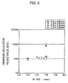
- FIG. 3 shows the minimum insulation resistance of each of the sample plugs that is measured along the lengthwise direction L of the insulator 20 in the range of the second reference plane 202 to the first reference plane 201.
- the horizontal axis indicates the outer diameter difference (D - D0), which represents the taper degree of the outer surface of the insulator end portion 24, while the vertical one indicates the resultant minimum insulation resistance with the plot of " ⁇ " for the sample spark plugs of S 1 and S2 having the T0 of 1.6 mm, the plot of " ⁇ " for the those of S3 - S6 having the T0 of 1.4 mm, the plot of " ⁇ ” for those of S7 - S9 having the T0 of 1.2 mm, the plot of " ⁇ ” for that of S10 having the T0 of 1.0 mm, and the plot of " ⁇ " for that of S11 having the T0 of 1.8 mm, respectively.
- a boundary line representing the reference insulation resistance of 130 M which corresponds to the minimum insulation resistance of a sample spark plug having the conventional type S11, is also designated in FIG. 3 for comparative evaluation.
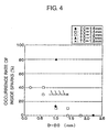
- FIG. 4 shows the determination results of the occurrence rate of inside sparks with the different sample spark plugs.
- the horizontal axis indicates the outer diameter difference (D - D0), while the vertical one indicates the resultant occurrence rate of inside sparks with the different plots designating different sample spark plugs in the same way as in FIG. 3.
- spark plug 100 high insulation properties and high ignition capability of the spark plug 100 can be secured through specifying the following relationships between the dimensional parameters D, D0, T0, and G in the spark plug 100:
- the metal shell 10 is also required to have a sufficient radial thickness so as to allow the ground electrode 40 to be joined thereto.
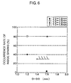
- the air pocket size T0 of the spark plug 100 is not greater than 1.6 mm.
- FIGS. 5 and 6 show the investigation results. It should be noted that the sample spark plugs tested in the investigation had different air pocket sizes T0 and outer diameter differences (D - D0), but the same spark gap size G of 1.1 mm, which is equal to the spark gap size G of the conventional type S 11 described above.
- the insulation resistance of the spark plug 100 was measured in more detail.
- FIG. 7 shows the measurement results.
- the horizontal axis indicates the distance of measuring plane from the second reference plane 202 in the lengthwise direction L of the insulator 20, while the vertical one indicates the measured insulation resistance with the plot of " ⁇ " for the sample plug of S3 having the outer diameter difference (D - D0) of 0.6 mm, the plot of " ⁇ " for that of S4 having the (D - D0) of 1.0 mm, the plot of " ⁇ " for that of S5 having the (D - D0) of 1.4 mm, and the plot of " ⁇ " for that of S6 having the (D - D0) of 1.8 mm.
- the insulation resistance increases in the lengthwise direction L of the insulator 20; in other words, the insulation resistance could keep the higher value in the deeper place inside the air pocket of the spark plug.
- the insulation resistance increases very slowly in the lengthwise direction L of the insulator 20. This means that carbon had already flowed into the air pocket of the spark plug deeply and deposited on the outer surface of the insulator end portion 24.
- the insulation resistance was also measured for sample spark plugs of S2 and S9, at 1 mm intervals in the lengthwise direction L of the insulator 20 from the second reference plane 202.
- FIG. 8 comparatively shows the measurement results with those of the sample plug of S6.
- the horizontal axis indicates the distance of measuring plane from the second reference plane 202 in the lengthwise direction L of the insulator 20, while the vertical one indicates the measured insulation resistance with the plot of " ⁇ " for the sample plug of S2 having the air pocket size T0 of 1.6 mm, the plot of " ⁇ " for that of S6 having the T0 of 1.4 mm, and the plot of " ⁇ " for that of S9 having the T0 of 1.2 mm.
- the third reference plane 203 is defined, as shown in FIG. 9, to extend parallel to and spaced the distance of 3 ⁇ T0 in the lengthwise direction L of the insulator 20 from the second reference plane 202.
- FIG. 9 there is also shown a fourth reference plane 204 that is defined to extend parallel to and spaced a distance of 1.5 ⁇ T0 in the lengthwise direction L of the insulator 20 from the second reference plane 202.
- the insulator end portion 24 has an outer diameter D3 and an outer diameter D4 on the third and fourth reference planes 203 and 204 respectively.
- the distance between the outer surface of the insulator end portion 24 and the inner surface of the metal shell 10 on the third reference plane 203 is designated as T3, while the same on the fourth reference plane 204 is designated as T4.
- the taper degree of the outer surface of the insulator end portion 24 in the range from the second reference plane 202 to the third reference plane 203 can be represented by (D3 - D0); similarly, the same in the range from the second reference plane 202 to the fourth reference plane 204 can be represented by (D4 - D0).
- sample spark plugs of seven different types S6 and S61 - S66 were the same values for some dimensional parameters, such as the air pocket size T0 of 1.4mm, the outer diameter D0 of 3.2 mm, the outer diameter D of 5.0 mm, and the spark gap size G of 0.9 mm.
- those sample spark plugs were made different from each other in at least one of the dimensional parameters D3, D4, T3, and T4. The detailed values of those parameters for each sample plug type are given in TABLE 2.
- FIG. 10 shows the measurement results of the minimum insulation resistance with those sample spark plugs.
- the horizontal axis indicates the outer diameter difference (D4 - D0), while the vertical one indicates the resultant minimum insulation resistance with the plot of " ⁇ " for the sample plugs of S6 and S63 having the outer diameter difference (D3 - D0) of 0.8 mm, the plot of " ⁇ ” for those of S61 and S65 having the (D3 - D0) of 1.3 mm, and the plot of " ⁇ " for those of (UNIT: mm) TYPE D0 D3 D3 - D0 D4 D4 -D0 T3 T4 S6 3.20 4.00 0.80 3.60 0.40 1.00 1.20 S61 3.20 4.50 1.30 3.60 0.40 0.75 1.20 S62 3.20 5.00 1.80 3.60 0.40 0.50 1.20 S63 3.20 4.00 0.80 4.00 0.80 1.00 1.00 1.00 S64 3.20 5.00 1.80 4.00 0.80 0.50 1.00 S65 3.20 4.50 1.30 4.50 1.30 0.75 0.75 S66 3.20 5.00 1.80 5.00 1.80 0.50 0.50 S65
- a boundary line representing the reference insulation resistance of 130 M is also designated in FIG. 10 for comparative evaluation.
- FIG. 11 shows the determination results of the occurrence rate of inside sparks with those sample spark plugs.
- the horizontal axis indicates the outer diameter difference (D4 - D0), while the vertical one indicates the resultant occurrence rate of inside sparks with the different plots designating different sample plugs in the same way as in FIG. 10.
- a boundary line representing the reference occurrence rate of inside sparks of 30 % is also designated in FIG. 11 for comparative evaluation.
- the occurrence rate of inside sparks exceeds the reference value of 30% in the sample plugs of S64 - S66, each of which had both a large (D3 - D0) and a large (D4 - D0). This is because when the outer diameters D3 and D4 are large, the distances T3 and T4 between the outer surface of the insulator end portion 24 and the inner surface of the metal shell 10 accordingly become small, thus causing more inside sparks in the spark plug.
- the outer diameter difference (D3 - D0) is preferably not greater than 1.8 mm and the outer diameter difference (D4 - D0) is preferably not greater than 0.8 mm, so as to secure sufficient insulation resistance and to effectively suppress generation of inside sparks.
- the outer diameter difference (D3 - D0) is not less than 1.0 mm, thereby allowing the previously-specified dimensional relationship of D - D0 ⁇ 1.0 mm to be definitely satisfied (since D3 ⁇ D).
- the inventors have also investigated the effect of the shape of the inner surface of the metal shell 10 on the insulation resistance and the occurrence rate of inside sparks of the spark plug 100.
- Sample spark plugs of a type S67 which is designed on the basis of the above-described type of S61, were fabricated for the investigation.
- the detailed values of dimensional parameters for the sample plug type S67 are given in TABLE 3, while the end portions of the metal shell 10 and the insulator 20 of a sample spark plug that has the type of S67 are shown in FIG. 12.
- the inner diameter of the metal shell 10 decreases, as shown in FIG. 12, from the second reference plane 202 that includes the end 10a of the metal shell 10 to the third reference plane 203 in the lengthwise direction L of the insulator 20.
- the inner surface of the metal shell 10 is tapered in the range of the second reference plane 202 to the third reference plane 203.
- the taper degree of the outer surface of the insulator end portion 24 is equal to zero in the same range of from the second reference plane 202 to the third reference plane 203. (UNIT: mm) TYPE D3 D4 T3 T4 S67 3.2 3.2 0.8 1.2
- sample plug type of S67 is designed to have the same values of T3 and T4, which are the distances between the inner surface of the metal shell 10 and the outer surface of the insulator end portion 24 on the third reference plane 203 and the fourth reference plane 204 respectively, as the prototype of S61 by tapering the inner surface of the metal shell 10 instead of the outer surface of the insulator end portion 24.
- FIG. 13 shows the measured minimum insulation resistance of the sample spark plug of S67 in comparison with that of a sample spark plug of S61.
- the plot of " ⁇ " designates the minimum insulation resistance of the sample plug of S61, while the plot of " ⁇ ” designates the same of the sample plug of S67.
- a boundary line representing the reference insulation resistance of 130 M is also designated in the same figure.
- the sample spark plug of S67 has a minimum insulation resistance higher than the reference insulation resistance but considerably lower that of the sample spark plug of S61.
- FIG. 14 shows the determined occurrence rate of inside sparks of the sample spark plug of S67 in comparison with that of the sample spark plug of S61.
- the different plots designate the values of the two sample spark plugs in the same way as in FIG. 13.
- a boundary line representing the reference value of 30 % is also designated in the same figure.
- the sample plug of S67 has an occurrence rate of inside sparks lower than the reference value of 30 % but considerably higher than that of the sample plug of S61, which is equal to zero.
- the two sample spark plugs have the same values of T3 and T4, the performance of the sample plug of S67 in insulation properties and in ignition capability becomes inferior to that of the sample plug of S67.
- the spark plug 100 it is preferable for the spark plug 100 that the inner diameter of the metal shell 10 is constant, or increases along the lengthwise direction L of the insulator 20 in the range from the second reference plane 202 to the third reference plane 203.
- the spark plug 100 has an improved structure characterized in that the dimensional parameters including the spark gap size G, the outer diameters D and D0 of the end portion 24 of the insulator 20 on the first and second reference planes 201 and 202, and the air pocket size T0 satisfy the following dimensional relationships:
- the improved structure ensures the spark plug 100 of high insulation properties and a high ignition capability.
- the first and second noble metal chips 35 and 45 are joined to the center and ground electrodes 30 and 40, respectively, by laser welding.
- joining means such as resistance welding, plasma welding, and adhesive joining.
- the two noble metal chips 35 and 45 which have a cylindrical shape in the previous embodiments, may also have a prismatic shape.
- center electrode 30 and the ground electrode 40 may not include the two noble metal chips 35 and 45 respectively.
- a spark plug according to the invention includes a metal shell that has a threaded portion with an outer diameter of 10 mm or less, or equal to 12 mm, an insulator, a center electrode, and a ground electrode.
- the spark plug has an improved structure in which an end portion of the insulator tapers toward an end thereof that protrudes from an end of the metal shell, and dimensional parameters, including a space G of the spark gap in the spark plug, a taper degree of the end portion of the insulator that is represented by an outer diameter difference (D - D0) in the end portion, and a size T0 of the air pocket formed in the spark plug, each have an effective range determined based on the experimental investigation results from the inventors.
- the structure ensures high insulation properties and high ignition capability of the spark plug.
Landscapes
- Spark Plugs (AREA)
Applications Claiming Priority (4)
| Application Number | Priority Date | Filing Date | Title |
|---|---|---|---|
| JP2004023015 | 2004-01-30 | ||
| JP2004023015 | 2004-01-30 | ||
| JP2004326659A JP2005243610A (ja) | 2004-01-30 | 2004-11-10 | スパークプラグ |
| JP2004326659 | 2004-11-10 |
Publications (1)
| Publication Number | Publication Date |
|---|---|
| EP1560309A2 true EP1560309A2 (de) | 2005-08-03 |
Family
ID=34656294
Family Applications (1)
| Application Number | Title | Priority Date | Filing Date |
|---|---|---|---|
| EP05001732A Withdrawn EP1560309A2 (de) | 2004-01-30 | 2005-01-27 | Zündkerze mit hohen Isolationseigenschaften und hoher Zündungsfähigkeit des Luft-Brennstoffgemisches. |
Country Status (4)
| Country | Link |
|---|---|
| US (1) | US7183702B2 (de) |
| EP (1) | EP1560309A2 (de) |
| JP (1) | JP2005243610A (de) |
| CN (1) | CN100459334C (de) |
Families Citing this family (16)
| Publication number | Priority date | Publication date | Assignee | Title |
|---|---|---|---|---|
| JP4658871B2 (ja) * | 2005-09-01 | 2011-03-23 | 日本特殊陶業株式会社 | スパークプラグ |
| JP2007242588A (ja) * | 2006-02-13 | 2007-09-20 | Denso Corp | 内燃機関用のスパークプラグ |
| KR20090034342A (ko) * | 2006-06-19 | 2009-04-07 | 페더럴-모걸 코오포레이숀 | 개선된 절연체 디자인을 가진 소직경/롱리치 스파크 플러그 |
| JP4719191B2 (ja) * | 2007-07-17 | 2011-07-06 | 日本特殊陶業株式会社 | 内燃機関用スパークプラグ |
| JP4430724B2 (ja) * | 2007-09-13 | 2010-03-10 | 日本特殊陶業株式会社 | スパークプラグ |
| WO2009069796A1 (ja) * | 2007-11-26 | 2009-06-04 | Ngk Spark Plug Co., Ltd. | スパークプラグ |
| JP5525454B2 (ja) | 2008-01-28 | 2014-06-18 | フラム・グループ・アイピー・エルエルシー | 高い位置のねじ山の接地シールド |
| DE112009000214T5 (de) * | 2008-01-28 | 2011-01-20 | Honeywell International Inc. | Dielektrisch verbesserte Zündkerze mit Gewindeteil |
| JP5386098B2 (ja) | 2008-03-21 | 2014-01-15 | 日本特殊陶業株式会社 | スパークプラグ |
| CN101881465B (zh) * | 2009-05-08 | 2012-05-16 | 清华大学 | 电子点火装置 |
| KR101397776B1 (ko) * | 2010-04-02 | 2014-05-20 | 니혼도꾸슈도교 가부시키가이샤 | 스파크 플러그 |
| JP4928626B2 (ja) * | 2010-09-21 | 2012-05-09 | 日本特殊陶業株式会社 | スパークプラグ |
| WO2013179640A1 (ja) * | 2012-05-28 | 2013-12-05 | 日本特殊陶業株式会社 | ガスケット及びその製造方法並びに点火プラグ及びその製造方法 |
| JP6035177B2 (ja) * | 2012-08-20 | 2016-11-30 | 株式会社デンソー | 内燃機関用のスパークプラグ |
| JP5778820B1 (ja) * | 2014-04-09 | 2015-09-16 | 日本特殊陶業株式会社 | スパークプラグ |
| CN111525395B (zh) * | 2019-02-03 | 2022-11-15 | 罗伯特·博世有限公司 | 用于火花塞的绝缘器和火花塞 |
Family Cites Families (7)
| Publication number | Priority date | Publication date | Assignee | Title |
|---|---|---|---|---|
| JPH0555490A (ja) | 1991-08-23 | 1993-03-05 | Mitsubishi Electric Corp | バツフア回路 |
| CN2265014Y (zh) * | 1996-08-16 | 1997-10-15 | 刘宪贵 | 一种抗积炭耐污火花塞 |
| JP3859410B2 (ja) * | 1999-11-16 | 2006-12-20 | 日本特殊陶業株式会社 | スパークプラグ |
| JP3711221B2 (ja) * | 1999-11-30 | 2005-11-02 | 日本特殊陶業株式会社 | スパークプラグ |
| US6653768B2 (en) | 2000-12-27 | 2003-11-25 | Ngk Spark Plug Co., Ltd. | Spark plug |
| JP4270784B2 (ja) | 2000-12-27 | 2009-06-03 | 日本特殊陶業株式会社 | スパークプラグ |
| JP2003317896A (ja) * | 2002-02-19 | 2003-11-07 | Denso Corp | スパークプラグ |
-
2004
- 2004-11-10 JP JP2004326659A patent/JP2005243610A/ja active Pending
-
2005
- 2005-01-27 EP EP05001732A patent/EP1560309A2/de not_active Withdrawn
- 2005-01-28 CN CNB2005100068397A patent/CN100459334C/zh not_active Expired - Fee Related
- 2005-01-31 US US11/046,247 patent/US7183702B2/en not_active Expired - Lifetime
Also Published As
| Publication number | Publication date |
|---|---|
| CN1649223A (zh) | 2005-08-03 |
| US20050168120A1 (en) | 2005-08-04 |
| JP2005243610A (ja) | 2005-09-08 |
| CN100459334C (zh) | 2009-02-04 |
| US7183702B2 (en) | 2007-02-27 |
Similar Documents
| Publication | Publication Date | Title |
|---|---|---|
| US8058785B2 (en) | Spark plug structure for improved ignitability | |
| US7183702B2 (en) | Spark plug with high insulation properties and high capability to ignite air-fuel mixture | |
| US7164225B2 (en) | Small size spark plug having side spark prevention | |
| US7605526B2 (en) | Spark plug for internal combustion engine | |
| US8853926B2 (en) | Spark plug with firing end having downward extending tines | |
| US7282844B2 (en) | High performance, long-life spark plug | |
| US20020093277A1 (en) | Structure of spark plug designed to provide high thermal resistance and durability | |
| WO2021111719A1 (ja) | スパークプラグ | |
| KR20100086491A (ko) | 스파크 플러그 | |
| US7122948B2 (en) | Spark plug having enhanced capability to ignite air-fuel mixture | |
| US9130356B2 (en) | Spark plug having a thin noble metal firing pad | |
| US7170219B2 (en) | Spark plug with multiple ground electrodes | |
| US7408294B2 (en) | Spark plug with high capability to ignite air-fuel mixture | |
| US20180069378A1 (en) | Spark plug | |
| US9614353B2 (en) | Spark plug | |
| JP2013041754A (ja) | スパークプラグ | |
| US9837796B2 (en) | Spark plug | |
| US7282845B2 (en) | Spark plug having a plurality of center electrodes | |
| US7221079B2 (en) | Spark plug with a plurality of ground electrodes | |
| US7541724B2 (en) | Spark plug requiring low discharge voltage and having high self-cleaning capability | |
| US7230369B2 (en) | Spark plug | |
| JP2006202684A (ja) | スパークプラグ | |
| JP7183933B2 (ja) | スパークプラグ | |
| JP2005183189A (ja) | スパークプラグ | |
| JP2002231414A (ja) | 内燃機関用スパークプラグ |
Legal Events
| Date | Code | Title | Description |
|---|---|---|---|
| PUAI | Public reference made under article 153(3) epc to a published international application that has entered the european phase |
Free format text: ORIGINAL CODE: 0009012 |
|
| AK | Designated contracting states |
Kind code of ref document: A2 Designated state(s): AT BE BG CH CY CZ DE DK EE ES FI FR GB GR HU IE IS IT LI LT LU MC NL PL PT RO SE SI SK TR |
|
| AX | Request for extension of the european patent |
Extension state: AL BA HR LV MK YU |
|
| STAA | Information on the status of an ep patent application or granted ep patent |
Free format text: STATUS: THE APPLICATION HAS BEEN WITHDRAWN |
|
| 18W | Application withdrawn |
Effective date: 20090604 |