EP1560310B1 - Pince à dénuder - Google Patents
Pince à dénuder Download PDFInfo
- Publication number
- EP1560310B1 EP1560310B1 EP05000263.3A EP05000263A EP1560310B1 EP 1560310 B1 EP1560310 B1 EP 1560310B1 EP 05000263 A EP05000263 A EP 05000263A EP 1560310 B1 EP1560310 B1 EP 1560310B1
- Authority
- EP
- European Patent Office
- Prior art keywords
- stripping
- conductor
- pliers
- stripping pliers
- lever
- Prior art date
- Legal status (The legal status is an assumption and is not a legal conclusion. Google has not performed a legal analysis and makes no representation as to the accuracy of the status listed.)
- Expired - Lifetime
Links
- 239000004020 conductor Substances 0.000 claims description 49
- 238000005520 cutting process Methods 0.000 claims description 29
- 238000009413 insulation Methods 0.000 claims description 11
- 230000009471 action Effects 0.000 claims description 2
- 230000001154 acute effect Effects 0.000 claims 1
- 238000013461 design Methods 0.000 description 6
- 230000006835 compression Effects 0.000 description 5
- 238000007906 compression Methods 0.000 description 5
- 239000002184 metal Substances 0.000 description 5
- 230000006978 adaptation Effects 0.000 description 2
- 238000013459 approach Methods 0.000 description 2
- 230000000712 assembly Effects 0.000 description 2
- 238000000429 assembly Methods 0.000 description 2
- 239000002360 explosive Substances 0.000 description 2
- 230000007246 mechanism Effects 0.000 description 2
- 238000005422 blasting Methods 0.000 description 1
- 230000008859 change Effects 0.000 description 1
- 238000011161 development Methods 0.000 description 1
- 230000018109 developmental process Effects 0.000 description 1
- 238000005553 drilling Methods 0.000 description 1
- 238000002955 isolation Methods 0.000 description 1
- 238000004519 manufacturing process Methods 0.000 description 1
- 238000005259 measurement Methods 0.000 description 1
- 230000036316 preload Effects 0.000 description 1
- 125000006850 spacer group Chemical group 0.000 description 1
- 238000012549 training Methods 0.000 description 1
Images




Classifications
-
- H—ELECTRICITY
- H02—GENERATION; CONVERSION OR DISTRIBUTION OF ELECTRIC POWER
- H02G—INSTALLATION OF ELECTRIC CABLES OR LINES, OR OF COMBINED OPTICAL AND ELECTRIC CABLES OR LINES
- H02G1/00—Methods or apparatus specially adapted for installing, maintaining, repairing or dismantling electric cables or lines
- H02G1/12—Methods or apparatus specially adapted for installing, maintaining, repairing or dismantling electric cables or lines for removing insulation or armouring from cables, e.g. from the end thereof
- H02G1/1202—Methods or apparatus specially adapted for installing, maintaining, repairing or dismantling electric cables or lines for removing insulation or armouring from cables, e.g. from the end thereof by cutting and withdrawing insulation
- H02G1/1204—Hand-held tools
- H02G1/1207—Hand-held tools the cutting element not rotating about the wire or cable
- H02G1/1209—Hand-held tools the cutting element not rotating about the wire or cable making a transverse cut
- H02G1/1212—Hand-held tools the cutting element not rotating about the wire or cable making a transverse cut using wire or cable clamping means
Definitions
- the invention relates to a wire stripper according to the preamble of claim 1
- a wire stripper is from the DE 79 33 957 U1 known.
- the pliers work with two jaws and two stripping knives.
- the mechanism is designed to pull, ie, each jaw and an insulating knife are pulled at an operation against a fixed jaw and a fixed Stripping.
- the movable jaw and the stripping blade are not coupled, so that the movable jaw and the stripping blade can be applied independently to the conductor.
- the invention solves this problem by the subject matter of claim 1.
- the folding lever each consist of a front folding lever plate and a congruent rear folding lever plate between which a gap is formed and in the gap between the folding lever plates movable attachment pieces for the upper Holder are used, on which on the one hand in each case springs - in particular coil springs - are supported, which press on the one hand, the jaw and the stripping in the slots in the direction of the further jaw and the other Abisollermessers and where else s support the L-shaped springs.
- the invention theoretically also two knife assemblies with two movable and two fixed Stripping or, more preferably - a jaw assembly with two jaws and a knife assembly with two Stripping made possible.
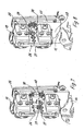
- Fig. 1 to 6 show a wire stripper 1 with two hand levers 2, 3.
- the one hand lever 2 - in Fig. 1 and 3 the right - the two hand lever is immovably connected directly to a base 4 and / or formed, whereas the other hand lever 3 - in Fig. 1 and 4 the left - is pivotally mounted on the base 4.
- the hand levers exist - as in Fig. 11 to recognize - each consisting of two sheets 5, 6, between which an air gap and which are aligned parallel to each other and by means of bolts 7 and spacers 8 are spaced from each other.
- the sheets 5, 6 in turn each consist of a handle portion 9 and a base portion 10, wherein the handle portions 9 in the mounted position of Fig. 1-3 are provided with a handle shell 11 - in particular made of plastic.
- a bearing bush 12 is placed on one of the bolts 7, a bearing bush 12 is placed.
- the second pivotable hand lever 3 consists of several stacked sheets 13 (see, eg Fig. 10 ), which are pivotally mounted on the base 4 between the base portions 10 of the sheets 5, 6.
- One of the sheets 13 of the pivotable hand lever 3 has at its the actual handle portion opposite end Projection 14 which rests on a control curve-like side edge 15 (will be described in more detail below).
- the hand lever 2, 3 are used for actuation by means of a hand, with which the second hand lever 3 is pulled in the direction of the first hand lever 2, wherein first cut through the insulation of a conductor 16 and then the separated insulation end 17 from the rest of the conductor or of its conductor ( n) 18 is deported.
- two folding lever 19, 20 are pivotally mounted for this purpose, which carry the actual functional elements for the realization of the clamping and / or stripping function.
- the folding lever 19, 20 exist after Fig. 12 each of a front folding lever plate 21, 22 and a congruent rear folding lever plate 23, 24, between which a gap is formed (see, for example Fig. 8b ).
- each a backdrop-like slot 29, 30 is formed, in each of which a further receiving bracket or holder 31, 32 on two sliding bolts 33, 34; 35, 36 slidably guided (see Fig. 2a ).
- a second, lower jaw 37 is attached and at the lower receiving angle 32 at the right here second folding lever 20, a second, lower stripping knife 38.
- the lower jaw 37 and the lower stripping 38th are mobile with it or guided here slidably, whereas the first jaw 26 serve as the upper fixed conductor stop for the conductor 16 and the upper stripping blade 28 as an abutment and counter-function element when severing the conductor insulation.
- the attachment pieces 66, 67 ( Fig. 12 and 1 ) each serve for receiving (eg for screwing on the holders 25, 27 of the upper clamping jaw 26 or of the upper stripping blade 38 through bores 68 of the folding lever plates, since the bores 68 for the screws 69 (FIG. Fig. 1 )
- the holders 35, 36 have a slightly larger diameter than the screws 69, thus the upper holder 25, 27 and thus the upper stripping blade 28 and the upper jaw 26 are arranged on the folding levers 19, 20 each movable limited.
- the upper jaw 26 and the upper stripping blade 28 are mounted with a little play in the corresponding holes 68 of the folding lever plates 21, 22. In this case act on them or here the attachment pieces 66, 67 respectively from above springs 41, 42, which here have an L-shape.
- the respective short leg of the L-shaped springs 41, 42 fastened and mounted in the end region acts on the upper side or the side of the upper clamping jaw 26 or the upper stripping blade 28 facing away from the oblong holes 29, 30 or, better, the respective fastening piece 66.
- the longitudinal legs of the L-shaped springs 41, 42 extend on the outer sides of the holder 25, 27 on the respective folding lever plate 21, 22 in the direction of the hand lever 2, 3 and are based with their ends on adjustable eccentric pins 43, 44 from, with which the spring preload in a simple manner by turning the eccentric pins 43, 44 is adjustable.
- control plates 45, 46 set here, which in the direction of the hand lever downwardly extending, interlocking lugs 47, 48, wherein the projection 14 of the pivoting hand lever 3 rests with its free end on the lower control plate 45.
- the folding lever 19, 20, which are hinged to the base 4 move away from each other, since a stationary arm 51 of a folding lever 19 cooperates with another control cam 52 here another control plate 53 on the other folding lever 20, wherein the boom 51 and this control cam are designed such that the folding lever 19, 20 on further compression of the hand lever 2, 3 move away from each other or open.
- the insulation end 17 is removed from the conductor 16 ( Fig. 10 ).
- the opening movement of the jaws 26, 37 and the stripping blades 28, 38 is due to the geometry of the control cam-like side edge 15 of a control plate 45 before opening the hand lever 2, 3.
- the coil springs 39, 40 act on the lower jaw 37 and the lower stripping blade and push these back to their starting position.
- the compression springs 49, 50 also support the opening movement of the hand lever 2, 3.
- both the clamping jaws 26, 37 and the stripping blades perpendicular to the "forceps plane" or here the image plane of the Fig. 1 a plurality of recesses 61a, b, ... and 62a, b, ... different size or different diameter. This allows adaptation to the conductor cross section used.
- Fig. 16 shows that each or at least one of the stripping blades 28, 38 also particularly advantageous (or according to a variant independently viewable) can be constructed in several parts. So it may consist of two metal layers 64, 65, of which one has the actual cutting edges 63 and the other corresponding recesses 62a ', 62b' to the recesses 62a, 62b, .. the layer 64 and the actual stripping, the Guide and position the ladder.
- the recesses 61a, 61b, ... of the jaws or at least one of the jaws and / or the recesses 62a, 62b, the stripping blades can have a semicircular shape or particularly advantageous (or according to a variant independently viewable) in sections, a more tapered geometry (eg, an acute-angled shape, see Fig. 13 - 16 ) so as to favorably influence the centering operation of the conductor and to provide spaces for the conductor insulation (below the projections).
- the pliers in particular with respect to the hand lever 2, 3 is not completely symmetrical, but also characterized by a symmetrical pliers comparable, pleasant operating feeling.
- a cutting device 54 is integrated into the wire stripper.
- This cutting device 54 is arranged below the lower stripping blade 38. It has a cutting blade 55, which is articulated to the base 4 and has at its one end a curved slot 56 into which a pin 57 engages the second hand lever 3. Leg compression of the lever 1,3 moves the pin 57 in the slot 56 until it finally comes to rest at the end and then the cutting blade 55 is pivoted on the base 4, so that a free end 58 of the cutting blade 55 can sever a conductor, the is inserted into a lateral recess 59 on the base.
- a knife guard 60 made of plastic is clamped in U-shape, which protects the user but does not interfere with the cutting of the conductor 16.
- Fig. 18,19 show a further wire stripper in a side view in two operating positions during the cutting process ( Fig. 18 . 20a, 20b ) and after stripping the conductor 77 with open hand levers 2, 3 ( Fig. 19 . 21 ad ).
- both the upper and the lower stripping knives 28, 38 of the second folding lever 20 have two sheet metal layers 70, 71, one of which has the actual cutting edge 72 with a plurality of juxtaposed recesses 73 for several conductors of the same diameter or for conductors of different diameters ( depending on the configuration) and the respective other corresponding recesses 74 which guide and position the conductor.
- the recesses 73 on the cutting edge are preferably configured in each case substantially semicircular at least at their base, so that in particular a thin conductor is optimally guided, fixed and cut.
- Fig. 18 additionally shows a conductor stop 75 on the second jaw with the cutting blades 28, 38, which is arranged on a measuring scale 76 movable, in particular displaceable, so that the length of the conductor 77 to be removed insulation / insulation 78 is adjustable adjustable in the simplest way.
- the upper and lower clamping jaws 80, 81 in the first hand lever have no contour adapted to the conductors contour but substantially rectangular in cross-section, flat recesses or gradations 82, each slightly wider than the diameter of the conductors 77 to be stripped so that they before the clamping something in the area of the jaws are movable and automatically take or find the optimal clamping position.
Landscapes
- Removal Of Insulation Or Armoring From Wires Or Cables (AREA)
Claims (19)
- Pince à dénuder (1) comprenanta. deux leviers à main (2, 3),b. deux leviers rabattables (19, 20) montés de manière à pouvoir pivoter au niveau d'une base (4),c. sachant qu'une paire de lames à dénuder (28, 38) mobiles l'une par rapport à l'autre est disposée au niveau d'un des deux leviers rabattables (19, 20) et qu'une paire de mâchoires de serrage (26, 37) mobiles l'une par rapport à l'autre ou une paire d'autres lames à dénuder est disposée au niveau de l'autre levier rabattable (20), etd. sachant que respectivement une lame à dénuder (38) ou une mâchoire de serrage (37) de chaque paire est guidée de manière à pouvoir coulisser dans un trou oblong (29, 30) du levier rabattable (19, 20) respectif,
caractérisée en ce quee. respectivement l'autre lame à dénuder (28) et/ou la mâchoire de serrage (26) correspondante sont disposées au niveau de la base (4) - sous l'action respectivement d'un ressort (41, 42) réalisé de manière à présenter une forme de L - avec un léger jeu au niveau des leviers rabattables (19, 20), sachant que le jeu est configuré de telle manière que des tolérances de conducteur lors du serrage d'un conducteur (16) et/ou lors du retrait de l'extrémité à dénuder (17) peuvent être compensées,f. sachant que les leviers rabattables (19, 20) sont constitués respectivement d'une tôle de levier rabattable avant (21, 22) et d'une tôle de levier rabattable arrière (23, 24) coïncidant avec la première, entre lesquelles est réalisée une fente,g. sachant que des pièces de fixation (66, 67) mobiles entre les tôles de levier rabattable (21, 22 ou 23, 24) pour les éléments d'appui supérieurs (25, 27) sont insérées dans la fente, au niveau desquelles s'appuient d'une part respectivement des ressorts - en particulier des ressorts hélicoïdaux (39, 40) - lesquels d'une part enfoncent la mâchoire de serrage (37) et la lame à dénuder (38) dans les trous oblongs (29, 30) en direction de l'autre mâchoire de serrage (37) ou de l'autre lame à dénuder (38), et au niveau desquelles s'appuient d'autre part les ressorts en forme de L (41, 42). - Pince à dénuder (1) selon la revendication 1, caractérisée en ce que l'un des leviers à main (2) est relié de manière immobile directement à la base (4) et/ou est réalisé de manière immobile, tandis que l'autre levier à main (3) est monté de manière à pouvoir pivoter au niveau de la base (4).
- Pince à dénuder (1) selon l'une quelconque des revendications précédentes, caractérisée en ce qu'une partie faisant saillie (14) est réalisée au niveau du levier à main (3) pouvant pivoter au niveau de la base (4), laquelle partie faisant saillie agit sur un contour (15) de type came de commande.
- Pince à dénuder (1) selon l'une quelconque des revendications précédentes, caractérisée en ce que les pièces de fixation (66, 67) servent à recevoir les éléments d'appui (25, 27) de la mâchoire de serrage supérieure (26) ou de la lame à dénuder supérieure (38).
- Pince à dénuder (1) selon l'une quelconque des revendications précédentes, caractérisée en ce que des alésages (68) sont réalisés dans les tôles de levier rabattables, lesquels présentent un diamètre légèrement plus grand que les vis (69) de sorte que les éléments d'appui supérieurs (25, 27) et donc la lame à dénuder supérieure (28) et la mâchoire de serrage supérieure (26) sont disposés respectivement de manière à pouvoir être déplacés de manière limitée au niveau des leviers rabattables (19, 20).
- Pince à dénuder (1) selon l'une quelconque des revendications précédentes, caractérisée en ce que les branches longitudinales des ressorts en forme de L (41, 42) s'étendent au niveau des côtés extérieurs des éléments d'appui (25, 27) sur la tôle de levier rabattable (21, 22) respective et s'appuient au niveau de tiges excentriques (43, 44) pouvant être déplacées, à l'aide desquelles la précontrainte de ressort des ressorts en forme de L (41, 42) peut être réglée.
- Pince à dénuder (1) selon l'une quelconque des revendications précédentes, caractérisée en ce que des tôles de commande (45, 46) sont placées entre les éléments d'appui inférieurs (31, 32) ou entre les tôles de levier rabattable (21 - 24), lesquelles présentent des appendices (47, 48) s'engrenant les uns dans les autres, s'étendant en direction des leviers à main (2, 3), sachant que la partie faisant saillie (14) du levier à main (3) pouvant pivoter repose au niveau de la tôle de commande inférieure (45).
- Pince à dénuder (1) selon l'une quelconque des revendications précédentes, caractérisée en ce que les lames de coupe (28, 38) et les mâchoires de serrage (26, 37) présentent plusieurs évidements (61 a, 61 b, ... 62a, 62b) servant à recevoir divers diamètres de conducteurs.
- Pince à dénuder (1) selon l'une quelconque des revendications précédentes, caractérisée en ce que les évidements (61 a, 61 b, ... 62a, 62b) sont réalisés de manière à présenter une forme semi-circulaire.
- Pince à dénuder (1) selon l'une quelconque des revendications précédentes, caractérisée en ce que les évidements (61 a, 61 b, ... 62a, 62b) se rétrécissent de manière à présenter un angle aigu au moins par endroits.
- Pince à dénuder (1) selon l'une quelconque des revendications précédentes, caractérisée en ce que chaque lame à dénuder ou au moins une des lames à dénuder (28, 38) présente une structure en plusieurs parties et est constituée de deux couches (64, 65 ; 70, 71), parmi lesquelles l'une des couches présente l'arête de coupe (63, 72) en soi et l'autre couche est réalisée sous la forme d'une plaque de guidage, qui est pourvue d'évidements (62a', 62b' ; 74) correspondants, lesquels guident et positionnent le conducteur (77).
- Pince à dénuder (1) selon la revendication 11, caractérisée en ce que la plaque de guidage ou la couche de tôle (71) des lames à dénuder (28, 38) repose directement au niveau de l'arête de coupe (72) de l'autre couche de tôle (70).
- Pince à dénuder (1) selon l'une quelconque des revendications 11 ou 12, caractérisée en ce que chacune des couches de tôle (70, 71) est pourvue de plusieurs des évidements (73, 74) pour les conducteurs ou le dénudage de conducteur.
- Pince à dénuder (1) selon l'une quelconque des revendications précédentes, caractérisée en ce qu'une butée de conducteur (75) réglable est disposée au niveau d'une graduation (76) au niveau de la mâchoire de serrage (21) pourvue de lames de coupe.
- Pince à dénuder (1) selon l'une quelconque des revendications précédentes, caractérisée en ce que les évidements (73, 74) dans la première et dans la deuxième couche de tôle (70, 71) sont configurés au moins au niveau de leur fond respectivement de manière à présenter essentiellement une forme semi-circulaire.
- Pince à dénuder (1) selon l'une quelconque des revendications précédentes, caractérisée en ce que la mâchoire de serrage supérieure et la mâchoire de serrage inférieure (80, 81) présentent des évidements (82) ou des paliers plats essentiellement de section transversale rectangulaire, lesquels sont respectivement légèrement plus larges que le diamètre des conducteurs (77) à dénuder.
- Pince à dénuder (1) selon l'une quelconque des revendications précédentes, caractérisée par un dispositif de coupe intégré servant à retirer une extrémité de conducteur pourvue d'une isolation et d'un ou de brins.
- Pince à dénuder (1) selon l'une quelconque des revendications précédentes, caractérisée en ce que le dispositif de coupe (54) présente une lame de coupe (55), qui est montée de manière articulée au niveau de la base (4) et qui présente, au niveau d'une de ses extrémités, un trou oblong (56) incurvé, avec lequel une tige (57) au niveau du deuxième levier à main (3) vient en prise.
- Pince à dénuder (1) selon l'une quelconque des revendications précédentes, caractérisée en ce qu'un évidement (59) latéral servant à insérer le conducteur (4) est réalisé dans la base (4), dans lequel est insérée une protection de lame (60).
Priority Applications (1)
| Application Number | Priority Date | Filing Date | Title |
|---|---|---|---|
| PL05000263T PL1560310T3 (pl) | 2004-02-02 | 2005-01-07 | Kleszcze do ściągania izolacji |
Applications Claiming Priority (4)
| Application Number | Priority Date | Filing Date | Title |
|---|---|---|---|
| DE202004001580 | 2004-02-02 | ||
| DE202004001580U | 2004-02-02 | ||
| DE202004014801U DE202004014801U1 (de) | 2004-02-02 | 2004-09-23 | Abisolierzange |
| DE202004014801U | 2004-09-23 |
Publications (3)
| Publication Number | Publication Date |
|---|---|
| EP1560310A2 EP1560310A2 (fr) | 2005-08-03 |
| EP1560310A3 EP1560310A3 (fr) | 2006-04-26 |
| EP1560310B1 true EP1560310B1 (fr) | 2015-03-04 |
Family
ID=34655010
Family Applications (1)
| Application Number | Title | Priority Date | Filing Date |
|---|---|---|---|
| EP05000263.3A Expired - Lifetime EP1560310B1 (fr) | 2004-02-02 | 2005-01-07 | Pince à dénuder |
Country Status (4)
| Country | Link |
|---|---|
| US (1) | US7096760B2 (fr) |
| EP (1) | EP1560310B1 (fr) |
| CN (1) | CN100459339C (fr) |
| PL (1) | PL1560310T3 (fr) |
Families Citing this family (27)
| Publication number | Priority date | Publication date | Assignee | Title |
|---|---|---|---|---|
| DE202006002004U1 (de) * | 2006-02-07 | 2007-06-21 | Weidmüller Interface GmbH & Co. KG | Abmantelwerkzeug |
| CN101310902B (zh) | 2007-05-24 | 2011-01-26 | 鸿准精密模具(昆山)有限公司 | 夹持装置及其使用方法 |
| DE102007038626B3 (de) * | 2007-08-16 | 2008-10-09 | Wezag Gmbh Werkzeugfabrik | Zange zum Abisolieren eines Kabels |
| DE202007015350U1 (de) * | 2007-11-02 | 2009-03-12 | Weidmüller Interface GmbH & Co. KG | Griffschale |
| CA2774428C (fr) * | 2009-10-14 | 2019-02-12 | Southwire Company | Station de travail a ensemble tete d'arrachage |
| US8978226B2 (en) * | 2012-06-11 | 2015-03-17 | Direct Source International, Llc | Hand tool for use in the quick disconnection of quick connect/disconnect couplings |
| US8863620B2 (en) * | 2012-07-19 | 2014-10-21 | Chao-Chin Yen | Hand tool with stripping and shearing functions |
| CN102882154B (zh) * | 2012-09-12 | 2015-09-30 | 嘉兴电力局 | 一种带电作业导线线夹的安装夹钳 |
| CN103056897B (zh) * | 2013-01-29 | 2015-03-04 | 河北亚大汽车塑料制品有限公司 | 包覆管剥皮机 |
| USD725454S1 (en) * | 2014-03-25 | 2015-03-31 | Hanlong Industrial Co., Ltd. | Tool handle |
| FR3030918B1 (fr) * | 2014-12-19 | 2017-12-01 | Airbus Operations Sas | Outil de denudage les cables electriques |
| US10033166B2 (en) * | 2015-06-29 | 2018-07-24 | Chao-Chin Yen | Stripping plier with supporting structure |
| CN104991099A (zh) * | 2015-07-08 | 2015-10-21 | 国网山东烟台市牟平区供电公司 | 一种电能计量用羊眼圈制作工具 |
| USD771458S1 (en) * | 2015-09-01 | 2016-11-15 | Chao-Chin Yen | Wire stripper |
| US9807992B2 (en) | 2015-09-14 | 2017-11-07 | Deshano, Inc. | Crankbait tuning device |
| CN106099775B (zh) * | 2016-07-28 | 2017-10-03 | 北京铁路局唐山供电段 | 一种电缆剥缆钳及其剥缆方法 |
| DE102017128226A1 (de) * | 2017-11-29 | 2019-05-29 | Rennsteig Werkzeuge Gmbh | Abisolierzange |
| CN107803777B (zh) * | 2017-12-04 | 2024-08-23 | 温州市三星通用机具厂 | 一种管件联接件拆卸工具 |
| CN109659873B (zh) * | 2019-02-20 | 2020-07-28 | 西格码电气股份有限公司 | 一种电工施工用多功能电线剥线钳 |
| WO2020253560A1 (fr) * | 2019-06-20 | 2020-12-24 | 常州市新拓工具有限公司 | Pince à dénuder |
| CN110459990A (zh) * | 2019-06-20 | 2019-11-15 | 常州市新拓工具有限公司 | 一种剥线钳 |
| CN111293576B (zh) * | 2020-03-18 | 2021-07-06 | 华昊众能检测技术集团有限公司 | 一种剥线钳用导线防损伤系统 |
| TWM622635U (zh) * | 2021-10-08 | 2022-01-21 | 亨龍工業有限公司 | 具有剪切功能的手工具 |
| CN114465167A (zh) * | 2022-02-17 | 2022-05-10 | 常州市新拓工具有限公司 | 剥线钳 |
| TWM634282U (zh) * | 2022-08-18 | 2022-11-11 | 亨龍工業有限公司 | 具有剝線功能的手工具 |
| CN118472851B (zh) * | 2024-07-09 | 2024-09-20 | 徐州东鹏工具制造有限公司 | 一种可调式剥线钳 |
| CN118472852B (zh) * | 2024-07-10 | 2024-09-24 | 浙江华胜工具有限公司 | 一种多口剥线钳及其使用方法 |
Family Cites Families (11)
| Publication number | Priority date | Publication date | Assignee | Title |
|---|---|---|---|---|
| US2842992A (en) * | 1955-02-15 | 1958-07-15 | Ideal Ind | Wire stripper |
| US2889728A (en) * | 1956-03-30 | 1959-06-09 | Ideal Ind | Wire stripper |
| US3177741A (en) * | 1962-04-20 | 1965-04-13 | Ideal Ind | Wire stripper |
| US3226815A (en) * | 1962-04-20 | 1966-01-04 | Ideal Ind | Method of stripping wire insulation |
| US3221576A (en) * | 1964-08-17 | 1965-12-07 | Te Ind Inc | Wire stripper |
| US3515018A (en) * | 1967-12-04 | 1970-06-02 | Ideal Ind | Device for stripping wires |
| DE7933957U1 (de) | 1979-12-01 | 1981-03-12 | Werkzeug-Union Gmbh -Dwu-, 5600 Wuppertal | Abisolierzange |
| CN2064549U (zh) * | 1990-02-02 | 1990-10-24 | 祁喜林 | 半自动剥线钳 |
| DE19707739C1 (de) * | 1997-02-27 | 1998-04-23 | Josef Krampe | Abisolierzange für ummantelte elektrische Kabel |
| FR2812133B1 (fr) * | 2000-07-19 | 2002-09-27 | Tech Modernes Alsaciennes | Pince a denuder |
| CN1417911A (zh) * | 2001-11-05 | 2003-05-14 | 中国石油化工股份有限公司 | 电缆剥线钳 |
-
2005
- 2005-01-07 EP EP05000263.3A patent/EP1560310B1/fr not_active Expired - Lifetime
- 2005-01-07 PL PL05000263T patent/PL1560310T3/pl unknown
- 2005-01-28 US US11/044,556 patent/US7096760B2/en not_active Expired - Fee Related
- 2005-02-01 CN CNB2005100059487A patent/CN100459339C/zh not_active Expired - Fee Related
Also Published As
| Publication number | Publication date |
|---|---|
| EP1560310A3 (fr) | 2006-04-26 |
| US7096760B2 (en) | 2006-08-29 |
| EP1560310A2 (fr) | 2005-08-03 |
| CN1652420A (zh) | 2005-08-10 |
| CN100459339C (zh) | 2009-02-04 |
| PL1560310T3 (pl) | 2015-08-31 |
| US20050166712A1 (en) | 2005-08-04 |
Similar Documents
| Publication | Publication Date | Title |
|---|---|---|
| EP1560310B1 (fr) | Pince à dénuder | |
| EP2081266B1 (fr) | Utilisation d'un couteau | |
| DE2119466A1 (de) | Vorrichtung zum Befestigen von Kabelanschlüssen | |
| DE2402187A1 (de) | Geraet zum abstreifen der verkleidung von bezogenen leitungen und dgl. | |
| DE3134311C2 (de) | Zangenartiges Handgerät zum Abisolieren von Leiterenden | |
| DE3241530A1 (de) | Abisolierzange | |
| DE102008062035A1 (de) | Schneidvorrichtung für bewehrte Kabel | |
| EP1557920B1 (fr) | Pince à dénuder avec adaptation automatique à des sections transversales différentes. | |
| EP2978088A1 (fr) | Pince à dénuder | |
| DE2416781C3 (de) | Abisolierzange | |
| EP1671407B1 (fr) | Pince a denuder automatique | |
| EP0678944B1 (fr) | Outil du genre pince pour torsader l'embout partiellement dénudé d'un conducteur isolé ayant une âme en forme de tresse | |
| DE202009001625U1 (de) | Vereinzelungsvorrichtung zum Abscheren von an einem Vorratsband aufgereihten Werkstücken | |
| DE3202036C2 (fr) | ||
| WO1994001906A1 (fr) | Dispositif servant a denuder des conducteurs et/ou des fils electriques | |
| DE2113107A1 (de) | Vorrichtung zum Durchschneiden und teilweisen Abisolieren elektrischer Draehte oder Kabel | |
| DE202004014801U1 (de) | Abisolierzange | |
| WO2021043807A1 (fr) | Insert de sertissage et pince de sertissage | |
| EP0390760A2 (fr) | Appareil pour attacher des contacts aux conducteurs électriques | |
| DE20301130U1 (de) | Abisolierzange | |
| DE68919412T2 (de) | Kombiniertes Werkzeug zum Schneiden und Abisolieren von Enden von elektrischen Kabeln, welche in einem isolierenden Mantel eingeschlossen sind. | |
| DE102020133953B3 (de) | Abisoliereinheit eines Presswerkzeugs, Presswerkzeug und Verfahren zur Montage einer Einstelleinheit | |
| DE2126671C3 (de) | Elektrische wärmeerzeugende Handwerkszange | |
| DE2120854C (de) | Vorrichtung zum Zerschneiden und Abisolieren eines Schaltdrahtes | |
| DE20315756U1 (de) | Automatische Abisolierzange |
Legal Events
| Date | Code | Title | Description |
|---|---|---|---|
| PUAI | Public reference made under article 153(3) epc to a published international application that has entered the european phase |
Free format text: ORIGINAL CODE: 0009012 |
|
| AK | Designated contracting states |
Kind code of ref document: A2 Designated state(s): AT BE BG CH CY CZ DE DK EE ES FI FR GB GR HU IE IS IT LI LT LU MC NL PL PT RO SE SI SK TR |
|
| AX | Request for extension of the european patent |
Extension state: AL BA HR LV MK YU |
|
| PUAL | Search report despatched |
Free format text: ORIGINAL CODE: 0009013 |
|
| AK | Designated contracting states |
Kind code of ref document: A3 Designated state(s): AT BE BG CH CY CZ DE DK EE ES FI FR GB GR HU IE IS IT LI LT LU MC NL PL PT RO SE SI SK TR |
|
| AX | Request for extension of the european patent |
Extension state: AL BA HR LV MK YU |
|
| 17P | Request for examination filed |
Effective date: 20060621 |
|
| AKX | Designation fees paid |
Designated state(s): AT BE BG CH CY CZ DE DK EE ES FI FR GB GR HU IE IS IT LI LT LU MC NL PL PT RO SE SI SK TR |
|
| 17Q | First examination report despatched |
Effective date: 20131021 |
|
| GRAP | Despatch of communication of intention to grant a patent |
Free format text: ORIGINAL CODE: EPIDOSNIGR1 |
|
| INTG | Intention to grant announced |
Effective date: 20141008 |
|
| GRAS | Grant fee paid |
Free format text: ORIGINAL CODE: EPIDOSNIGR3 |
|
| GRAA | (expected) grant |
Free format text: ORIGINAL CODE: 0009210 |
|
| AK | Designated contracting states |
Kind code of ref document: B1 Designated state(s): AT BE BG CH CY CZ DE DK EE ES FI FR GB GR HU IE IS IT LI LT LU MC NL PL PT RO SE SI SK TR |
|
| REG | Reference to a national code |
Ref country code: GB Ref legal event code: FG4D Free format text: NOT ENGLISH |
|
| REG | Reference to a national code |
Ref country code: CH Ref legal event code: EP |
|
| REG | Reference to a national code |
Ref country code: RO Ref legal event code: EPE |
|
| REG | Reference to a national code |
Ref country code: IE Ref legal event code: FG4D Free format text: LANGUAGE OF EP DOCUMENT: GERMAN |
|
| REG | Reference to a national code |
Ref country code: CH Ref legal event code: NV Representative=s name: ISLER AND PEDRAZZINI AG, CH |
|
| REG | Reference to a national code |
Ref country code: AT Ref legal event code: REF Ref document number: 714593 Country of ref document: AT Kind code of ref document: T Effective date: 20150415 |
|
| REG | Reference to a national code |
Ref country code: DE Ref legal event code: R096 Ref document number: 502005014702 Country of ref document: DE Effective date: 20150416 |
|
| REG | Reference to a national code |
Ref country code: PT Ref legal event code: SC4A Free format text: AVAILABILITY OF NATIONAL TRANSLATION Effective date: 20150507 |
|
| REG | Reference to a national code |
Ref country code: SE Ref legal event code: TRGR |
|
| REG | Reference to a national code |
Ref country code: ES Ref legal event code: FG2A Ref document number: 2538139 Country of ref document: ES Kind code of ref document: T3 Effective date: 20150617 Ref country code: NL Ref legal event code: T3 |
|
| PG25 | Lapsed in a contracting state [announced via postgrant information from national office to epo] |
Ref country code: LT Free format text: LAPSE BECAUSE OF FAILURE TO SUBMIT A TRANSLATION OF THE DESCRIPTION OR TO PAY THE FEE WITHIN THE PRESCRIBED TIME-LIMIT Effective date: 20150304 Ref country code: FI Free format text: LAPSE BECAUSE OF FAILURE TO SUBMIT A TRANSLATION OF THE DESCRIPTION OR TO PAY THE FEE WITHIN THE PRESCRIBED TIME-LIMIT Effective date: 20150304 |
|
| REG | Reference to a national code |
Ref country code: LT Ref legal event code: MG4D |
|
| PG25 | Lapsed in a contracting state [announced via postgrant information from national office to epo] |
Ref country code: GR Free format text: LAPSE BECAUSE OF FAILURE TO SUBMIT A TRANSLATION OF THE DESCRIPTION OR TO PAY THE FEE WITHIN THE PRESCRIBED TIME-LIMIT Effective date: 20150605 |
|
| REG | Reference to a national code |
Ref country code: PL Ref legal event code: T3 |
|
| PG25 | Lapsed in a contracting state [announced via postgrant information from national office to epo] |
Ref country code: SK Free format text: LAPSE BECAUSE OF FAILURE TO SUBMIT A TRANSLATION OF THE DESCRIPTION OR TO PAY THE FEE WITHIN THE PRESCRIBED TIME-LIMIT Effective date: 20150304 Ref country code: EE Free format text: LAPSE BECAUSE OF FAILURE TO SUBMIT A TRANSLATION OF THE DESCRIPTION OR TO PAY THE FEE WITHIN THE PRESCRIBED TIME-LIMIT Effective date: 20150304 |
|
| PG25 | Lapsed in a contracting state [announced via postgrant information from national office to epo] |
Ref country code: IS Free format text: LAPSE BECAUSE OF FAILURE TO SUBMIT A TRANSLATION OF THE DESCRIPTION OR TO PAY THE FEE WITHIN THE PRESCRIBED TIME-LIMIT Effective date: 20150704 |
|
| REG | Reference to a national code |
Ref country code: DE Ref legal event code: R097 Ref document number: 502005014702 Country of ref document: DE |
|
| PLBE | No opposition filed within time limit |
Free format text: ORIGINAL CODE: 0009261 |
|
| STAA | Information on the status of an ep patent application or granted ep patent |
Free format text: STATUS: NO OPPOSITION FILED WITHIN TIME LIMIT |
|
| REG | Reference to a national code |
Ref country code: FR Ref legal event code: PLFP Year of fee payment: 12 |
|
| PG25 | Lapsed in a contracting state [announced via postgrant information from national office to epo] |
Ref country code: DK Free format text: LAPSE BECAUSE OF FAILURE TO SUBMIT A TRANSLATION OF THE DESCRIPTION OR TO PAY THE FEE WITHIN THE PRESCRIBED TIME-LIMIT Effective date: 20150304 |
|
| 26N | No opposition filed |
Effective date: 20151207 |
|
| PG25 | Lapsed in a contracting state [announced via postgrant information from national office to epo] |
Ref country code: SI Free format text: LAPSE BECAUSE OF FAILURE TO SUBMIT A TRANSLATION OF THE DESCRIPTION OR TO PAY THE FEE WITHIN THE PRESCRIBED TIME-LIMIT Effective date: 20150304 |
|
| PGFP | Annual fee paid to national office [announced via postgrant information from national office to epo] |
Ref country code: NL Payment date: 20160120 Year of fee payment: 12 |
|
| REG | Reference to a national code |
Ref country code: HU Ref legal event code: AG4A Ref document number: E025806 Country of ref document: HU |
|
| PG25 | Lapsed in a contracting state [announced via postgrant information from national office to epo] |
Ref country code: BE Free format text: LAPSE BECAUSE OF NON-PAYMENT OF DUE FEES Effective date: 20160131 |
|
| PG25 | Lapsed in a contracting state [announced via postgrant information from national office to epo] |
Ref country code: LU Free format text: LAPSE BECAUSE OF FAILURE TO SUBMIT A TRANSLATION OF THE DESCRIPTION OR TO PAY THE FEE WITHIN THE PRESCRIBED TIME-LIMIT Effective date: 20160107 |
|
| GBPC | Gb: european patent ceased through non-payment of renewal fee |
Effective date: 20160107 |
|
| PG25 | Lapsed in a contracting state [announced via postgrant information from national office to epo] |
Ref country code: MC Free format text: LAPSE BECAUSE OF FAILURE TO SUBMIT A TRANSLATION OF THE DESCRIPTION OR TO PAY THE FEE WITHIN THE PRESCRIBED TIME-LIMIT Effective date: 20150304 |
|
| PG25 | Lapsed in a contracting state [announced via postgrant information from national office to epo] |
Ref country code: HU Free format text: LAPSE BECAUSE OF NON-PAYMENT OF DUE FEES Effective date: 20160108 Ref country code: GB Free format text: LAPSE BECAUSE OF NON-PAYMENT OF DUE FEES Effective date: 20160107 |
|
| REG | Reference to a national code |
Ref country code: IE Ref legal event code: MM4A |
|
| REG | Reference to a national code |
Ref country code: FR Ref legal event code: PLFP Year of fee payment: 13 |
|
| PG25 | Lapsed in a contracting state [announced via postgrant information from national office to epo] |
Ref country code: IE Free format text: LAPSE BECAUSE OF NON-PAYMENT OF DUE FEES Effective date: 20160107 Ref country code: RO Free format text: LAPSE BECAUSE OF NON-PAYMENT OF DUE FEES Effective date: 20150304 |
|
| PG25 | Lapsed in a contracting state [announced via postgrant information from national office to epo] |
Ref country code: PT Free format text: LAPSE BECAUSE OF NON-PAYMENT OF DUE FEES Effective date: 20161007 |
|
| PG25 | Lapsed in a contracting state [announced via postgrant information from national office to epo] |
Ref country code: PL Free format text: LAPSE BECAUSE OF NON-PAYMENT OF DUE FEES Effective date: 20160107 |
|
| REG | Reference to a national code |
Ref country code: NL Ref legal event code: MM Effective date: 20170201 |
|
| PG25 | Lapsed in a contracting state [announced via postgrant information from national office to epo] |
Ref country code: NL Free format text: LAPSE BECAUSE OF NON-PAYMENT OF DUE FEES Effective date: 20170201 |
|
| REG | Reference to a national code |
Ref country code: FR Ref legal event code: PLFP Year of fee payment: 14 |
|
| PGFP | Annual fee paid to national office [announced via postgrant information from national office to epo] |
Ref country code: CZ Payment date: 20180104 Year of fee payment: 14 Ref country code: CH Payment date: 20180119 Year of fee payment: 14 Ref country code: ES Payment date: 20180226 Year of fee payment: 14 |
|
| PG25 | Lapsed in a contracting state [announced via postgrant information from national office to epo] |
Ref country code: CY Free format text: LAPSE BECAUSE OF FAILURE TO SUBMIT A TRANSLATION OF THE DESCRIPTION OR TO PAY THE FEE WITHIN THE PRESCRIBED TIME-LIMIT Effective date: 20150304 |
|
| PGFP | Annual fee paid to national office [announced via postgrant information from national office to epo] |
Ref country code: AT Payment date: 20180122 Year of fee payment: 14 Ref country code: FR Payment date: 20180119 Year of fee payment: 14 Ref country code: SE Payment date: 20180119 Year of fee payment: 14 Ref country code: IT Payment date: 20180129 Year of fee payment: 14 |
|
| PG25 | Lapsed in a contracting state [announced via postgrant information from national office to epo] |
Ref country code: BG Free format text: LAPSE BECAUSE OF FAILURE TO SUBMIT A TRANSLATION OF THE DESCRIPTION OR TO PAY THE FEE WITHIN THE PRESCRIBED TIME-LIMIT Effective date: 20150304 |
|
| PG25 | Lapsed in a contracting state [announced via postgrant information from national office to epo] |
Ref country code: CZ Free format text: LAPSE BECAUSE OF NON-PAYMENT OF DUE FEES Effective date: 20190107 |
|
| REG | Reference to a national code |
Ref country code: CH Ref legal event code: PL |
|
| REG | Reference to a national code |
Ref country code: AT Ref legal event code: MM01 Ref document number: 714593 Country of ref document: AT Kind code of ref document: T Effective date: 20190107 |
|
| PG25 | Lapsed in a contracting state [announced via postgrant information from national office to epo] |
Ref country code: SE Free format text: LAPSE BECAUSE OF NON-PAYMENT OF DUE FEES Effective date: 20190108 Ref country code: FR Free format text: LAPSE BECAUSE OF NON-PAYMENT OF DUE FEES Effective date: 20190131 |
|
| PG25 | Lapsed in a contracting state [announced via postgrant information from national office to epo] |
Ref country code: CH Free format text: LAPSE BECAUSE OF NON-PAYMENT OF DUE FEES Effective date: 20190131 Ref country code: LI Free format text: LAPSE BECAUSE OF NON-PAYMENT OF DUE FEES Effective date: 20190131 Ref country code: AT Free format text: LAPSE BECAUSE OF NON-PAYMENT OF DUE FEES Effective date: 20190107 |
|
| PG25 | Lapsed in a contracting state [announced via postgrant information from national office to epo] |
Ref country code: IT Free format text: LAPSE BECAUSE OF NON-PAYMENT OF DUE FEES Effective date: 20190107 |
|
| REG | Reference to a national code |
Ref country code: ES Ref legal event code: FD2A Effective date: 20200309 |
|
| PG25 | Lapsed in a contracting state [announced via postgrant information from national office to epo] |
Ref country code: ES Free format text: LAPSE BECAUSE OF NON-PAYMENT OF DUE FEES Effective date: 20190108 |
|
| PGFP | Annual fee paid to national office [announced via postgrant information from national office to epo] |
Ref country code: DE Payment date: 20230123 Year of fee payment: 19 |
|
| P01 | Opt-out of the competence of the unified patent court (upc) registered |
Effective date: 20230525 |
|
| REG | Reference to a national code |
Ref country code: DE Ref legal event code: R119 Ref document number: 502005014702 Country of ref document: DE |
|
| PG25 | Lapsed in a contracting state [announced via postgrant information from national office to epo] |
Ref country code: TR Free format text: LAPSE BECAUSE OF NON-PAYMENT OF DUE FEES Effective date: 20160107 |
|
| PG25 | Lapsed in a contracting state [announced via postgrant information from national office to epo] |
Ref country code: DE Free format text: LAPSE BECAUSE OF NON-PAYMENT OF DUE FEES Effective date: 20240801 |
|
| PG25 | Lapsed in a contracting state [announced via postgrant information from national office to epo] |
Ref country code: DE Free format text: LAPSE BECAUSE OF NON-PAYMENT OF DUE FEES Effective date: 20240801 |