EP1560329B1 - Dispositif de prédistorsion digital utilisant un modèle à base de séries de puissances - Google Patents
Dispositif de prédistorsion digital utilisant un modèle à base de séries de puissances Download PDFInfo
- Publication number
- EP1560329B1 EP1560329B1 EP05250413A EP05250413A EP1560329B1 EP 1560329 B1 EP1560329 B1 EP 1560329B1 EP 05250413 A EP05250413 A EP 05250413A EP 05250413 A EP05250413 A EP 05250413A EP 1560329 B1 EP1560329 B1 EP 1560329B1
- Authority
- EP
- European Patent Office
- Prior art keywords
- signal
- digital
- distortion
- multiplier
- digital predistorter
- Prior art date
- Legal status (The legal status is an assumption and is not a legal conclusion. Google has not performed a legal analysis and makes no representation as to the accuracy of the status listed.)
- Expired - Lifetime
Links
Images


Classifications
-
- F—MECHANICAL ENGINEERING; LIGHTING; HEATING; WEAPONS; BLASTING
- F24—HEATING; RANGES; VENTILATING
- F24F—AIR-CONDITIONING; AIR-HUMIDIFICATION; VENTILATION; USE OF AIR CURRENTS FOR SCREENING
- F24F13/00—Details common to, or for air-conditioning, air-humidification, ventilation or use of air currents for screening
- F24F13/30—Arrangement or mounting of heat-exchangers
-
- H—ELECTRICITY
- H03—ELECTRONIC CIRCUITRY
- H03F—AMPLIFIERS
- H03F1/00—Details of amplifiers with only discharge tubes, only semiconductor devices or only unspecified devices as amplifying elements
- H03F1/32—Modifications of amplifiers to reduce non-linear distortion
- H03F1/3241—Modifications of amplifiers to reduce non-linear distortion using predistortion circuits
- H03F1/3258—Modifications of amplifiers to reduce non-linear distortion using predistortion circuits based on polynomial terms
-
- F—MECHANICAL ENGINEERING; LIGHTING; HEATING; WEAPONS; BLASTING
- F24—HEATING; RANGES; VENTILATING
- F24F—AIR-CONDITIONING; AIR-HUMIDIFICATION; VENTILATION; USE OF AIR CURRENTS FOR SCREENING
- F24F12/00—Use of energy recovery systems in air conditioning, ventilation or screening
- F24F12/001—Use of energy recovery systems in air conditioning, ventilation or screening with heat-exchange between supplied and exhausted air
- F24F12/006—Use of energy recovery systems in air conditioning, ventilation or screening with heat-exchange between supplied and exhausted air using an air-to-air heat exchanger
-
- H—ELECTRICITY
- H03—ELECTRONIC CIRCUITRY
- H03F—AMPLIFIERS
- H03F1/00—Details of amplifiers with only discharge tubes, only semiconductor devices or only unspecified devices as amplifying elements
- H03F1/32—Modifications of amplifiers to reduce non-linear distortion
- H03F1/3241—Modifications of amplifiers to reduce non-linear distortion using predistortion circuits
- H03F1/3247—Modifications of amplifiers to reduce non-linear distortion using predistortion circuits using feedback acting on predistortion circuits
-
- H—ELECTRICITY
- H03—ELECTRONIC CIRCUITRY
- H03F—AMPLIFIERS
- H03F1/00—Details of amplifiers with only discharge tubes, only semiconductor devices or only unspecified devices as amplifying elements
- H03F1/32—Modifications of amplifiers to reduce non-linear distortion
- H03F1/3241—Modifications of amplifiers to reduce non-linear distortion using predistortion circuits
- H03F1/3294—Acting on the real and imaginary components of the input signal
-
- H—ELECTRICITY
- H03—ELECTRONIC CIRCUITRY
- H03F—AMPLIFIERS
- H03F2200/00—Indexing scheme relating to amplifiers
- H03F2200/336—A I/Q, i.e. phase quadrature, modulator or demodulator being used in an amplifying circuit
-
- H—ELECTRICITY
- H03—ELECTRONIC CIRCUITRY
- H03F—AMPLIFIERS
- H03F2201/00—Indexing scheme relating to details of amplifiers with only discharge tubes, only semiconductor devices or only unspecified devices as amplifying elements covered by H03F1/00
- H03F2201/32—Indexing scheme relating to modifications of amplifiers to reduce non-linear distortion
- H03F2201/3209—Indexing scheme relating to modifications of amplifiers to reduce non-linear distortion the amplifier comprising means for compensating memory effects
Definitions
- the present invention relates to a technique for reducing nonlinear distortion in amplifiers, and more particularly, to digital predistortion based on a power series model.
- Digital predistortion is a technique for canceling distortion produced in a power amplifier by adding an inverse distortion component to the signal input to the power amplifier.
- the amplitude and the phase of the distortion component to be added to the input signal have to be controlled at high accuracy.
- One method for realizing the predistortion is using a lookup-table type predistorter configured to look for an appropriate distortion component from the lookup table corresponding to the input signal. This method is described in H. Girard and K. Feher, "A New Baseband Linearizer for More Efficient Utilization of Earth Station Amplifiers Used for QPSK Transmission", IEEE J. Select Areas Commun., Vol.SAC-1, No. 1, 1983.
- a power series predistorter that represents the nonlinear distortion characteristic of the power amplifier using a power series model is known. See, for example, Okamoto, Nojima, and Ohoyama, "Analysis and Compensation of nonlinear distortion in a travelling-wave tube amplifier based on IF Band Predistortion", IEICE Technical Study Report, MW76-112, 1976.
- G. Lazzarin, S. Pupolin, and A. Sarti discloses a technique for controlling polynomial coefficients of a digital predistorter.
- a covariance matrix is calculated for the signal generated by the digital predistorter, and the difference between the output signal of the power amplifier and the signal generated by the digital predistorter is used as an error to control the polynomial coefficients of the predistorter.
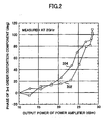
- FIG. 2 is a chart showing an experimental result measuring the relative phase of a third-order distortion component as a function of output level of a power amplifier.
- a pair of fundamental waves (or carrier waves) 102 and 104 with a center frequency f0, as illustrated in FIG. 1B are input to the power amplifier at various power levels, and the output signals are measured.
- third-order distortion components (nonlinear components) 106 and 108 appear in the output signal from the power amplifier.
- the third and higher distortions are generated; however, only the third-order distortion components are illustrated in FIG. 1B for the sake of simplification.
- the two plots 202 and 204 shown in the chart of FIG. 2 correspond to the lower part third-order distortion 106 and the upper part third-order distortion 108 shown in FIG. 1B , respectively. Ideally, these two plots are consistent with each other over the entire output power range. If these two components agree with each other, compensating for one of the third-order distortion leads directly to compensation for the other (paired) distortion component. In contrast, if the two components do not agree with each other, a nonlinear component still remains in the signal unless both distortion components are compensated for.
- these two distortion components are close to each other at a low power level (for example, at or below 20 dBm), as illustrated in FIG. 2 .
- a low power level for example, at or below 20 dBm
- the two plots 202 and 204 do not agree with each other, which means that compensation of distortion components becomes difficult in a range in which the output backoff is insufficient.
- the value of the third or higher order distortion component varies depending on frequency. This phenomenon is known as the "memory effect".
- a method for excluding the memory effect using a time-varying filter model is described in H. Ku, D. McKinley and J.S. Kenny, "Quantifying Memory Effects in RF Power Amplifiers", IEEE Transactions on Microwave Theory and Techniques, Vol.50, No. 12, pp.2843-2849, Dec. 2002 .
- the input signal being input to the predistorter has a certain degree of randomness, and accordingly, the memory effect may vary in response to the input signal varying over time.
- the frequency-dependent nonlinearity may vary over time.
- the conventional predistorters cannot follow such a change over time satisfactorily, and consideration of highly precise nonlinearity compensation has not been made sufficiently.
- the predistorter may hollow the change over time in the distortion component using a pilot signal.
- the distortion component has to be compensated for using a pilot signal within, for example, the period of training sequence, independently from the signal transmission.
- the pilot signal cannot always be acquired, it is difficult to easily and accurately compensate for the distortion using a pilot signal.
- compensating for the distortion using a pilot signal includes many steps, such as inputting a prescribed pilot signal to the predistorter, supplying the output of the predistorter to the power amplifier, scanning the entire frequency range to detect nonlinear distortion components, and controlling various parameters so as to reduce the detected distortion components. Accordingly, the process and the structure may become complicated.
- US 2001/050592A discloses a digital predistorter according to the precharacterizing portion of claim 1.
- the invention is a digital predistorter as defined in claim 1.
- the present invention can solve the above-described problems in the prior art, and to provide a digital predistorter capable of highly precise nonlinear distortion compensation for a power amplifier based on power series analysis.
- the tap coefficient of the finite impulse response filter is adaptively controlled so as to introduce the nonlinear distortion component that can efficiently cancel the distortion generated in the power amplifier, and accordingly, distortion compensation accuracy can be improved.
- the reference signal is, for example, a feed-forward signal derived from the digital input signal.
- the adaptive control is performed based on the signal that has not been subjected to amplification, and therefore, the control speed can be increased.
- the reference signal may be a feedback signal derived from the output of the power amplifier.
- the adaptive control is performed based on the actually amplified signal, and therefore, distortion compensation accuracy can be further improved.
- the feedback signal is obtained by, for example, subtracting a first signal in proportion to the digital input signal or to a power of the digital input signal from a second signal derived from an output of the power amplifier.
- a nonlinear distortion component that is to be compensated for can be extracted.
- the adaptive controller may be configured to receive both the feed-forward signal and the feedback signal as the reference signals. In this case, the adaptive controller adjusts the tap coefficient of the finite impulse filter so as to reduce the difference between the feed-forward signal and the feedback signal.
- a transmitter using such a digital predistorter comprises a power amplifier configured to amplify a digital transmission signal, and the digital predistorter connected to the power amplifier and configured to compensate for nonlinear distortion of the power amplifier using the power series model.
- the transmitter can transmit a signal under efficient control of nonlinearity compensation.
- FIG. 3 is a schematic diagram illustrating a part of a transmitter using a digital predistorter which may be an embodiment of the invention.
- the signal transmission system of the transmitter includes a digital predistorter 302, a digital-to-analog converter (DAC) 304, an orthogonal modulator 306, a frequency converter 308, and a power amplifier 310.
- the feedback system of the transmitter includes a directional coupler 312, a frequency converter 314, an orthogonal demodulator 316, and an analog-to-digital converter (ADC) 318.
- the digital predistorter 302 has a pair of coefficient multipliers 320, a pair of adders 322, a pair of distortion generating units 324, and an adaptive controller 326.
- the digital predistorter 302 receives a digital signal to be transmitted (referred to as a "digital transmission signal"), as indicated at the top left of the figure.
- the inphase component (I component) and the quadrature component (Q component) of the digital signal are input to the digital predistorter 302 separately from each other.
- the digital transmission signal is generally a baseband signal, however, it may be a signal of an intermediate frequency band, depending on the use.
- the inphase component and the quadrature component of the digital transmission signal are supplied to the associated coefficient multipliers 320, and the amplitude and/or the phase of each component is adjusted by an amount corresponding to an appropriate fixed number "a1" (generally, a complex number). Each of the adjusted components is supplied to one of the input terminals of the associated adder 322.
- the inphase component and the quadrature component of the input digital signal are also supplied to the associated distortion generating units 324, which generate nonlinear distortion signals for the corresponding components.
- the nonlinear distortion signal of each component is supplied to the other input terminal of the associated adder 322.
- the adaptive controller 326 controls the operation of the distortion generating units 324. The detailed operation of the digital predistorter 302 is described below.
- Each of the digital-to-analog converters 304 converts one of the nonlinear distortion-added digital inphase component and quadrature component output from the digital predistorter 302 into an analog form.
- the orthogonal modulator 306 combines the inphase component (I) and the quadrature component (Q) into a modulation signal.
- the frequency converter 308 upconverts the baseband or intermediate-band modulation signal to a radio frequency (RF) signal.
- RF radio frequency
- the power amplifier 310 amplifies the power level of the RF signal so as to be suitable for radio transmission.
- the output signal of the power amplifier 310 contains a distortion component generated by nonlinear amplification, as well as a linearly amplified signal component. The influence of the nonlinear distortion is cancelled by inverse distortion given by the digital predistorter 302 to the digital transmission signal prior to the power amplification.
- the signal output from the power amplifier 310 is treated as an output of the transmitter, and transmitted from an antenna (not shown).
- the directional coupler 312 of the feedback system extracts a portion of the amplified signal to be transmitted.
- the frequency converter 314 downconverts the radio frequency band of the extracted signal to a baseband or an intermediate band.
- the orthogonal demodulator 316 separates the downconverted signal into an inphase component (I) and a quadrature component (Q).
- the analog-to-digital converters 318 convert the analog inphase component and the analog quadrature component to digital forms, respectively, and supply the digitally-converted components to the adaptive controller 326.
- FIG. 4 illustrates the detailed structure of the digital predistorter 302. Since the basic idea of signal processing is the same for both the inphase component and the quadrature component, illustration is made of only one of the components for simplification (e.g., only the inphase component).
- the path for the third-order distortion component in the distortion generating unit 324 includes a third-order multiplier 402, a coefficient multiplier 404, a finite impulse response filter (FIR 3 ) 406 for the third order distortion, and an adder 408.
- the path for the fifth-order distortion component in the distortion generating unit 324 includes a fifth-order multiplier 412, a coefficient multiplier 414, a finite impulse response filter (FIR 5 ) 416 for the fifth order distortion, and an adder 418.
- paths for the higher order distortions are provided in the distortion generating unit 324.
- Each of the coefficient multipliers 320, 404, and 414 multiplies the input signal by a prescribed constant (generally, a complex number) indicated as "a1", “a3", or "a5" in the figure.
- the third order multiplier 402 raises the input signal to the third power
- the fifth order multiplier 412 raises the input signal to the fifth power.
- Each of the FIR 3 406 and the FIR 5 416 estimates and outputs a weighted average of the input signal and the past data (previously input signals). The weighting is called a tap coefficient.
- the digital filter FIR filter
- the digital filter may be configured so as to use Fourier transforms and inverse Fourier transforms to perform the major arithmetic operations at the frequency range.
- Such digital signal processing can be executed using existing means, such as microprocessors, DSPs, or FPGAs.
- U 3 ⁇ m H u 3 m , u 3 ⁇ m - 1 , ... , u 3 ⁇ m - N .
- the higher order signal components x 7 , x 9 , ... can be obtained in the same manner.
- the output x 1 of the coefficient multiplier 320 corresponds to a linearly amplified digital transmission signal.
- the output x 3 of the third order FIR filter (FIR 3 ) corresponds to the third order distortion (nonlinear) component represented by the nonlinearly amplified signal
- the output x 5 of the fifth order FIR filter (FIR 5 ) corresponds to the fifth order distortion (nonlinear) component represented by the nonlinearly amplified signal.
- the seventh and the higher order distortion components can be obtained.
- the nonlinear distortion components are expressed as odd-order terms.
- the output signal y(m) described above only represents one of the inphase component and the quadrature component
- the actual output signal of the digital predistorter 302 contains the inphase component yi(m) and the quadrature component yq(m).
- the i-th order distortion component is expressed as the i-th order term of the power series polynomial (8).
- the coefficient bi of the term represents the contribution of the i-th distortion component.
- both the output of the digital predistorter 302 and the input to the power amplifier 310 are treated as y(t) for the purpose of simplification.
- a signal extracted by the directional coupler 312 is downconverted at the frequency converter 314, and separated into the inphase component and the quadrature component at the orthogonal demodulator 316.
- the separated components are converted to digital forms at the analog-to-digital converters 318.
- the digitized components are input as feedback signals to the digital predistorter 302.
- the feedback signals are monitored by the digital predistorter 302, and indicated as Z mon (i) (m) and Z mon (q) (m) in FIG. 3 .
- Z mon (m) For simplification purpose, one of the feedback signals is referred to as Z mon (m).
- output signal x 1 of the coefficient multiplier 320 (in which the distortion components have not been introduced yet by the distortion generating unit 324).
- the output signal z 1 of the power amplifier contains a linear component due to linear amplification of signal x1 and a nonlinear component due to nonlinear amplification of signal x1.
- ci denotes the coefficient of the term of i-th power.
- the power series coefficient ci can be determined from the input and output characteristics of the power amplifier 310.
- the difference Z mon (m)-z 1 (m) represents an output signal obtained when only the distortion components x 3 (m), x 5 (m), ... generated by the distortion generating unit 324 of the digital predistorter 302 are linearly amplified at the power amplifier 310.
- Each of the terms in Equation (15) corresponds to the error signal e 2i+1 of the associated order (e.g., the third order, the fifth order, ).
- the tap coefficient of each of the FIR filters is adaptively adjusted so as to minimize the terms of Equation (15). Since the tap coefficients are adaptively controlled in accordance with the frequency-dependency or the change over time of the distortion component, efficient predistortion can be realized.
- the error signal e 3 (m) for the third order distortion is obtained by subtracting the estimated contribution of the seventh and higher order terms from the difference Z mon (m)-z 1 (m).
- a distortion component x 3 that can cancel the third order distortion introduced by the power amplifier 310 can be generated at the distortion generating unit 324.
- a distortion component x 5 that can cancel the fifth order distortion introduced by the power amplifier 310 can be generated at the distortion generating unit 324.
- the distortion components X 2i+1 that can cancel the higher order distortion components are also generated in the same manner.
- the error signal e 2i+1 is an evaluation function that has to be made as small as possible in adaptive control. It can be understood from Equations (17) and (18) that the error signals do not contain thermal noise or random errors. Accordingly, the error signals can be minimized, independent of thermal noise or random errors, in the adaptive control of the tap coefficients.
- many existing algorithms such as a steepest descent method, an LMS method, or an RLS, can be used. Alternatively, a Kalman filter may be used.
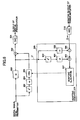
- FIG. 5 is a block diagram illustrating an example, outside the scope of the invention, of the digital predistorter 302. In the example shown in FIG. 5 , only the third order distortion is considered, and the fifth and higher order distortion components are neglected.
- the adaptive controller 326 includes a coefficient multiplier 502, a subtractor 504, and an adaptive algorithm unit 506.
- the output of the coefficient multiplier 502 is C 1 X 1 , which corresponds to z 1 explained in the previous example.
- the adaptive algorithm unit 506 receives the error signal e 3 , and adjusts the tap coefficient of the filter FIR 3 406 so as to minimize the error signal e 3 by executing an adaptive algorithm described above.
- FIG. 6 is a block diagram illustrating a first embodiment of the digital predistorter 302.
- the adaptive controller 326 includes a third-order multiplier 602, a coefficient multiplier 604, and a subtractor 606, in addition to the coefficient multiplier 502, the subtractor 504, and the adaptive algorithm unit 506.
- the output of the coefficient multiplier 502 is C 1 X 1
- the output of the other coefficient multiplier 604 is c 1 x 1 3 .
- the adaptive algorithm unit 507 receives the error signal e 3 , and adjusts the tap coefficient of the filter FIR 3 406 so as to minimize the error signal e 3 .
- the term (b 3 -c 3 )x 1 3 of Equation (14) is considered, unlike the example shown in FIG. 5 . Consequently, the error signal e 3 is determined more precisely, as compared with the example of FIG. 5 .
- FIG. 7 is a block diagram illustrating a second embodiment of the digital predistorter 302.
- the adaptive controller 326 includes a coefficient multiplier 502, a subtractor 504, a third-order multiplier 602, a coefficient multiplier 604, a subtractor 606, and an adaptive algorithm unit 716 for FIR 3 .
- the adaptive controller 326 further includes a fifth order multiplier 702, a coefficient multiplier 704, a subtractor 706, a coefficient multiplier 708, a subtractor 710, a coefficient multiplier 712, a subtractor 714, and an adaptive algorithm unit 718 for FIR 5 .
- Equation (22) corresponds to Equation (14).
- the output of the coefficient multiplier 708 is c 1 x 5
- b 1 c 1
- b 3 c 3
- b 5 c 5 .
- This output is an error signal for the third order distortion.
- the adapttive algorithm unit 716 receives the error signal e 3 , and adaptively controls the tap coefficient of filter FIR 3 406 so as to minimize the error signal e 3 .
- FIG. 8A through FIG. 8C are diagrams of signal spectra.
- the baseband feedback signal Z mon contains a linearly amplified fundamental wave component 802, a nonlinearly amplified third order distortion component 803, and a nonlinearly amplified fifth order distortion component 805.
- the signal x 1 of the fundamental wave is raised to power 3 or power 5, and multiplied by an appropriate coefficient to obtain z 1 .
- the component z 1 is subtracted from the feedback signal Z mon , the fundamental wave 802 and portions of the nonlinear distortion components are removed, as illustrated in FIG. 8B . Since the remaining fifth order distortion component is obtained as the output of the coefficient multiplier 708, the remaining component is further subtracted by the subtractor 710.
- the resultant component is the third order distortion component e 3 , as illustrated in FIG. 8C .
- the third order distortion component is obtained as the output of the coefficient multiplier 712, this component is also subtracted by the subtractor 714, and the fifth distortion component e 5 is extracted.
- FIG. 9 is a schematic diagram illustrating a modification of the transmitter using the digital predistorter.
- the output of the finite impulse response filters FIR 3 and FIR 5 are connected to the inputs of the multipliers 402 and 412, respectively.
- This structure is different from that shown in FIG. 4 , in which the inputs to the filters FIR 3 and FIR 5 are connected to the outputs of the multipliers.
- the multipliers 402 and 404 may be used as a part of the power amplifier 310.
- the structure or the operation of the output end of the power amplifier for example, the drain of the MOSFET
- occurrence of nonlinear distortion in the power amplifier 310 or the accuracy of the compensating distortion component generated by the distortion generating unit 324 may vary depending on whether the FIR filter is positioned before or after the multiplier.
- the FIR filters by placing the FIR filters at the input end of the multipliers 402 and 412, nonlinearity can be reduced and the accuracy of the compensating distortion component can be improved.
- FIG. 10 is a schematic diagram illustrating another modification of the transmitter using the digital predistorter 302.
- FIR filters are inserted before and after the multipliers.
- FIR filters FTR F3 406 and FIR B3 407 are placed respectively before and after the multiplier 402
- FIR filters FIR F5 416 and FIR B5 417 are placed respectively before and after the multiplier 412. This arrangement can further improve the accuracy of the compensating distortion component, while reducing nonlinear component.
- FIG. 11 is a flowchart of the operation carried out to control the tap coefficients of the FIR filters shown in FIG. 10 .
- the process starts.
- a front filter (or a prefilter) FIR F placed on the input side of the i-th order multiplier (where i is an odd number greater than or equal to 3) is selected as the current filter whose tap coefficient is to be controlled.
- the front filter FIR F3 406 for the third order distortion is selected for the control.
- adaptive control is performed to determine the tap coefficient so as to minimize the error signal (or the reference signal) e i .
- step 1110 If there is an uncontrolled front filter FIR F still existing (NO in S1108), the degree "i" is incremented, and the process returns to step 1104 to repeat steps 1104, 1106, and 1148. If all the front filters have been controlled in step 1108, then the process proceeds to step 1110.
- a back filter (or a postfilter) FIR B placed on the output side of the i-th order multiplier is selected as the current filter whose tap coefficient is to be controlled.
- the back filter FIR B3 407 for the third order distortion is selected.
- adaptive control is performed to determine the tap coefficient so as to minimize the error signal (or the reference signal) e i .
- step 1114 it is determined whether the tap coefficients of all the back filters FIR B positioned at the output ends of the multipliers have been controlled. If there is an uncontrolled back filter FIR B still existing (NO in S1114), the degree "i" is incremented, and the process returns to step 1110 to repeat steps 1110, 1112, and 1114. If all the back filters have been controlled in step 1114, then the process terminates at step 1116.
- the tap coefficient of the front filter placed before the multiplier is adjusted, and then, the tap coefficient of the back filter placed after the multiplier is adjusted.
- the adjusting order may be changed. Simultaneous adjustment at both the input end and the output end is unsuitable because the number of parameters being varied increases, and time and workload required to converge to the appropriate solution may increase.
- FIG. 12 is a block diagram of a digital predistorter 1202 which may be an embodiment of the invention.
- the digital predistorter 1202 has a coefficient multiplier 1204 and an adder 1206 on the path for the fundamental wave, and has an adaptive controller 1226 on the feed-forward path.
- the digital predistorter 1202 also has a multiplier 1208, a coefficient multiplier 1210, a finite impulse response filter FIR 3 1212, and an adder 1214 on the path for the third order distortion.
- a multiplier 1218, a coefficient multiplier 1220, a finite impulse response filter FIR 5 1222, and an adder 1224 are provided on the path for the fifth order distortion.
- similar paths are provided for higher order distortion components.
- Each of the coefficient multipliers 1204, 1210, and 1220 multiplies the input signal by a prescribed constant (generally, a complex number) indicated as "a1", “a3", or "a5" in the figure.
- the third order multiplier 1208 raises the input signal to the third power
- the fifth order multiplier 1218 raises the input signal to the fifth power.
- Each of FIR 3 and FIR 5 estimates and outputs a weighted average of the input signal and the past data (previously input signals).
- U 3 ⁇ m H u 3 m , u 3 ⁇ m - 1 , ... , u 3 ⁇ m - N .
- the higher order signal components x 7 , x 9 , ... can be obtained in the same manner.
- the adaptive controller 1226 of the second embodiment receives the digital transmission signal u(m) input to the digital predistorter 12012, and creates a new weighting factor based on the received signal u(m) and the past weighting information.
- the updating vector is selected depending on the employed adaptive algorithm.
- the initial value of the weighting vector may be set in advance in the adaptive algorithm by measuring the frequency-dependency of the distortion component of the power amplifier 310 in advance. Alternatively, the initial value may be set to zero at the beginning, using an algorithm that can learn to find the appropriate initial value through the running of the algorithm.
- the tap coefficient can be controlled promptly.
- the signal processing required for the feedback loop is eliminated, and the adaptive control can be carried out using a simple structure, although, from the viewpoint of improving precision, the feedback control of the first embodiment is preferable.
- FIG. 13 is a block diagram illustrating a digital predistorter 1302 which may be an embodiment of the invention.
- the digital predistorter 1302 may be used in place of the digital predistorter 302 shown in FIG. 3 .
- the digital predistorter 1302 is configured such that the adaptive controller 1326 receives a feedback signal, in addition to the digital transmission signal u(m). In other words, both a feedback control loop and a feed-forward control loop are provided.
- the adaptive controller 1326 receives a digital transmission signal u(m), which is a feed-forward signal supplied through the feed-forward path, as well as a feedback signal u'(m) through the feedback path, which is generated from the signal having actually passed through the power amplifier 310.
- the adaptive control is performed to adjust the tap coefficients so as to minimize the difference e(m) between the feed-forward signal u(m) and the feedback signal u'(m).
- e m u m - u ⁇ m
- the error signal e(m) does not contain thermal noise or random errors, and therefore, highly precise adaptive control can be performed.
- the weighting factors for the fifth and higher order distortions can be determined in the same manner.
- FIG. 14 is a block diagram illustrating an example, outside the scope of the invention, of the digital predistorter 1302. In this example, only the third order distortion is considered, and the fifth and higher order distortion components are neglected, as in the example shown in FIG. 5 .
- the adaptive controller 1326 of this example includes a subtractor 1404 and an adaptive algorithm unit 1406.
- the power level of the feedback signal is regulated to the appropriate level in either the digital or analog domain. The power level may be adjusted in either domain. If the operating range of the analog-to-digital converter (ADC) 318 is not broad enough, then it is desired to adjust the power level of the signal in the digital domain.
- ADC analog-to-digital converter
- the precision of the output signal from the ADC may be degraded. Since the gain of the power amplifier 310 is known, to what power level the feedback signal is adjusted can be determined precisely.
- the subtractor 1404 outputs an error signal e(m), which represents the difference between the feed-forward signal u(m) and the appropriately level-adjusted feedback signal u'(m), to the adaptive algorithm unit 1406.
- the adaptive algorithm unit 1406 controls the tap coefficient of the filter FIR3 1212 so as to minimize the error signal e(m), using a known adaptive algorithm, such as one described above.
- FIG. 15 is a block diagram illustrating another example of the digital predistorter 1302, outside the scope of the invention.
- the adaptive controller 1326 of this example includes a coefficient multiplier 1502 and a subtractor 1504, in addition to the adaptive algorithm unit 1406 and the subtractor 1404.
- the adaptive algorithm unit 1406 controls the tap coefficient of filter FIR 3 1212 so as to minimize the error signal e(m), using Equation (30).
- FIG. 16 is a block diagram illustrating a third embodiment of the digital predistorter 1302 of the invention.
- the adaptive controller 1326 of this example includes a third-order multiplier 1602, a coefficient multiplier 1604, and subtractors 1606 and 1608, in addition to the coefficient multiplier 1502, the subtractor 1504, and the adaptive algorithm unit 1407.
- the adaptive algorithm unit 1407 controls the tap coefficient of filter FIR 3 1212 so as to minimize the error signal e(m), using Equation (30).
- FIG. 17 is a block diagram illustrating a fourth embodiment of the digital predistorter 1302 of invention.
- the adaptive controller 1326 includes a coefficient multiplier 1502, a subtractor 1504, a third-order multiplier, a coefficient multiplier 1604, a subtractor 1606, and an adaptive algorithm unit 1716 for controlling the FIR 3 for the third order distortion.
- the adaptive controller 1326 includes a fifth-order multiplier 1702, a coefficient multiplier 1704, a subtractor 1706, a coefficient multiplier 1708, a subtractor 1710, a coefficient multiplier 1712, a subtractor 1714, an adaptive algorithm unit 1718 for controlling FIR 5 , and subtractors 1720 and 1722.
- the subtractor 1720 generates and outputs an error signal e 3 (m) with respect to the third order distortion, to the adaptive algorithm unit 1716.
- the adaptive algorithm unit 1716 controls the tap coefficient of the filter FIR 3 1212 so as to minimize the error signal e 3 (m).
- the subtractor 1722 generates and outputs an error signal e 5 (m) with respect to the fifth order distortion, to the adaptive algorithm unit 1718.
- the adaptive algorithm unit 1718 controls the tap coefficient of the filter FIR 5 1222 so as to minimize the error signal e 5 (m).
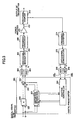
- FIG. 18 is schematic diagram illustrating a part of a transmitter employing a digital predistorter 1302 shown in FIG. 13 , in which the finite impulse response filters FIR 3 and FIR 5 are placed after the coefficient multipliers 1210 and 1220, respectively.
- distortion compensation is performed for each of the inphase component (I) and the quadrature component (Q).
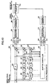
- FIG. 19 is a schematic diagram illustrating a part of a transmitter using a digital predistorter 1302 whose structure is similar to that shown in FIG. 13 .
- the outputs of the finite impulse response filters FIR 3 and FIR 5 are connected to the inputs of the multipliers 1208 and 1218, respectively.
- FIR filters are placed on both sides of the associated multiplier in each path.
- a front filter FIR F3 1213 and a back filter FIR B3 1212 are placed respectively before and after the coefficient multiplier 1210 in the path for the third order distortion
- a front filter FIR F5 1223 and a back filter FIR B5 1222 are placed respectively before and after the coefficient multiplier 1220 in the path for the fifth order distortion.
Landscapes
- Engineering & Computer Science (AREA)
- Physics & Mathematics (AREA)
- Power Engineering (AREA)
- Nonlinear Science (AREA)
- Algebra (AREA)
- General Engineering & Computer Science (AREA)
- Mechanical Engineering (AREA)
- Combustion & Propulsion (AREA)
- Chemical & Material Sciences (AREA)
- General Physics & Mathematics (AREA)
- Mathematical Analysis (AREA)
- Mathematical Optimization (AREA)
- Pure & Applied Mathematics (AREA)
- Amplifiers (AREA)
- Filters That Use Time-Delay Elements (AREA)
- Transmitters (AREA)
Claims (10)
- Dispositif de prédistorsion numérique (302, 1302) utilisant un modèle à base de séries de puissances en vue de compenser une distorsion non linéaire d'un amplificateur de puissance, comprenant :une unité de génération de distorsion (324) configurée de manière à introduire une composante de distorsion non linéaire d'un ordonnancement prescrit dans un signal d'entrée numérique (u) délivré au niveau du dispositif de prédistorsion numérique, l'unité de génération de distorsion présentant un multiplicateur (402) configuré de manière à élever le signal d'entrée numérique à une puissance prescrite compatible avec l'ordonnancement prescrit de la composante de distorsion non linéaire, et un filtre RIF (406) connecté en série avec le multiplicateur; etun contrôleur adaptatif (326) configuré de manière à recevoir un signal de référence et à ajuster de manière adaptative un coefficient de prise du filtre RIF (406) de manière à amener le signal de référence vers un niveau désiré ;caractérisé en ce que le contrôleur adaptatif présente un premier soustracteur (504) configuré de manière à recevoir une partie du signal d'entrée numérique par le biais d'un multiplicateur de coefficient (502) et une sortie de moniteur de l'amplificateur de puissance pour générer en sortie un premier résultat de soustraction, et un second soustracteur (606) configuré de manière à recevoir le premier résultat de soustraction et la partie du signal d'entrée numérique élevé à la puissance prescrite, en vue de générer en sortie un second résultat de soustraction ; etcaractérisé en ce que le second résultat de soustraction est utilisé en qualité de signal de référence pour ajuster de manière adaptative le coefficient de prise du filtre RIF.
- Dispositif de prédistorsion numérique selon la revendication 1, dans lequel le contrôleur adaptatif (326) est configuré de manière à déterminer le coefficient de prise sur la base de signaux numériques actuels et antérieurs entrés au niveau du dispositif de prédistorsion numérique.
- Dispositif de prédistorsion numérique selon la revendication 1 ou 2, dans lequel le signal de référence est au moins l'un parmi un signal de prédistorsion dérivé du signal d'entrée numérique et un signal de rétroaction dérivé d'une sortie de l'amplificateur de puissance.
- Dispositif de prédistorsion numérique selon la revendication 3, dans lequel le contrôleur adaptatif est configuré de manière à recevoir le signal de prédistorsion et le signal de rétroaction en qualité de signaux de référence, et à ajuster le coefficient de prise du filtre récursif de manière à réduire la différence entre le signal de prédistorsion et le signal de rétroaction.
- Dispositif de prédistorsion numérique selon l'une quelconque des revendications précédentes, dans lequel l'unité de génération de distorsion est configurée de manière à introduire une pluralité de différents ordonnancements de composantes de distorsion non linéaire dans le signal d'entrée numérique.
- Dispositif de prédistorsion numérique selon la revendication 5, dans lequel l'unité de génération de distorsion présente une pluralité d'ensembles du multiplicateur (1208, 1218) et le filtre récursif (1212, 1222) connectés en série, chaque ensemble étant délivré vers un chemin respectif correspondant à l'un des différents ordonnancements de composantes de distorsion non linéaire.
- Dispositif de prédistorsion numérique selon l'une quelconque des revendications précédentes, dans lequel une sortie du multiplicateur est connectée à une entrée du filtre RIF.
- Dispositif de prédistorsion numérique selon l'une quelconque des revendications 1 à 6, dans lequel une sortie du filtre RIF est connectée à une entrée du multiplicateur.
- Dispositif de prédistorsion numérique selon la revendication 1, dans lequel l'unité de génération de distorsion présente en outre un second filtre RIF connecté en série avec le multiplicateur, et dans lequel l'un (406) des filtres non récursifs est positionné avant le multiplicateur (402) et l'autre (407) est positionné après le multiplicateur.
- Émetteur comprenant :un amplificateur de puissance configuré de manière à amplifier un signal de transmission numérique ; etun dispositif de prédistorsion numérique selon l'une quelconque des revendications précédentes, connecté à l'amplificateur de puissance et configuré de manière à compenser la distorsion non linéaire de l'amplificateur de puissance en faisant appel à un modèle à base de séries de puissances.
Applications Claiming Priority (2)
| Application Number | Priority Date | Filing Date | Title |
|---|---|---|---|
| JP2004021031 | 2004-01-29 | ||
| JP2004021031A JP4255849B2 (ja) | 2004-01-29 | 2004-01-29 | べき級数型ディジタルプリディストータ |
Publications (2)
| Publication Number | Publication Date |
|---|---|
| EP1560329A1 EP1560329A1 (fr) | 2005-08-03 |
| EP1560329B1 true EP1560329B1 (fr) | 2011-03-09 |
Family
ID=34650810
Family Applications (1)
| Application Number | Title | Priority Date | Filing Date |
|---|---|---|---|
| EP05250413A Expired - Lifetime EP1560329B1 (fr) | 2004-01-29 | 2005-01-27 | Dispositif de prédistorsion digital utilisant un modèle à base de séries de puissances |
Country Status (7)
| Country | Link |
|---|---|
| US (1) | US7418056B2 (fr) |
| EP (1) | EP1560329B1 (fr) |
| JP (1) | JP4255849B2 (fr) |
| KR (1) | KR100659592B1 (fr) |
| CN (1) | CN100426663C (fr) |
| DE (1) | DE602005026740D1 (fr) |
| ES (1) | ES2361998T3 (fr) |
Families Citing this family (70)
| Publication number | Priority date | Publication date | Assignee | Title |
|---|---|---|---|---|
| US8380143B2 (en) | 2002-05-01 | 2013-02-19 | Dali Systems Co. Ltd | Power amplifier time-delay invariant predistortion methods and apparatus |
| US8811917B2 (en) | 2002-05-01 | 2014-08-19 | Dali Systems Co. Ltd. | Digital hybrid mode power amplifier system |
| JP4255849B2 (ja) | 2004-01-29 | 2009-04-15 | 株式会社エヌ・ティ・ティ・ドコモ | べき級数型ディジタルプリディストータ |
| US7590190B2 (en) * | 2004-11-10 | 2009-09-15 | Powerwave Technologies, Inc. | System and method for forward path gain control in a digital predistortion linearized transmitter |
| DE602006000525T2 (de) * | 2005-06-03 | 2009-02-05 | Ntt Docomo Inc. | Mehrbandvorverzerrer mit Korrekturwertetabellen |
| JP4344367B2 (ja) * | 2005-06-06 | 2009-10-14 | 株式会社エヌ・ティ・ティ・ドコモ | 多周波帯用べき級数型プリディストータ |
| US7653147B2 (en) * | 2005-08-17 | 2010-01-26 | Intel Corporation | Transmitter control |
| JP4720468B2 (ja) * | 2005-12-07 | 2011-07-13 | 日本電気株式会社 | 非線形歪み補償回路及びその方法並びにそれを用いた無線送信システム |
| CA2576778C (fr) * | 2006-02-07 | 2014-09-02 | Xinping Huang | Circuit multiport a auto-etalonnage et methode connexe |
| US8995502B1 (en) * | 2006-04-04 | 2015-03-31 | Apple Inc. | Transceiver with spectral analysis |
| US7755425B2 (en) * | 2006-04-10 | 2010-07-13 | Telefonaktiebolaget L M Ericsson (Publ) | Method and apparatus for reducing frequency memory effects in RF power amplifiers |
| US7778352B2 (en) * | 2006-12-21 | 2010-08-17 | Broadcom Corporation | Digital compensation for nonlinearities in a polar transmitter |
| CN104202279A (zh) | 2006-12-26 | 2014-12-10 | 大力系统有限公司 | 用于多信道宽带通信系统中的基带预失真线性化的方法和系统 |
| ES2366666T3 (es) * | 2006-12-27 | 2011-10-24 | Telefonaktiebolaget Lm Ericsson (Publ) | Determinación de un nivel de reducción de potencia para un transmisor. |
| DE102007028695A1 (de) | 2007-06-21 | 2009-01-02 | Kathrein-Austria Ges.M.B.H. | Verfahren und Vorrichtung zur Erzeugung eines amplituden-modulierten Signals |
| US7688138B2 (en) * | 2008-03-24 | 2010-03-30 | Harris Corporation | Electronic device having a predistortion filter and related methods |
| JP5228723B2 (ja) * | 2008-09-10 | 2013-07-03 | 富士通株式会社 | 歪補償装置及び方法 |
| JP5071370B2 (ja) | 2008-12-26 | 2012-11-14 | 富士通株式会社 | 歪補償装置及び方法 |
| EP2204910B1 (fr) * | 2008-12-30 | 2013-07-03 | ST-Ericsson SA | Convertisseur numérique-analogique |
| US8462881B2 (en) * | 2008-12-31 | 2013-06-11 | Ubidyne, Inc. | Method for digitally predistorting a payload signal and radio station incorporating the method |
| JP5338378B2 (ja) | 2009-03-02 | 2013-11-13 | 富士通株式会社 | 歪補償装置及び方法 |
| US20100323641A1 (en) * | 2009-06-22 | 2010-12-23 | Qualcomm Incorporated | Method and apparatus for using pre-distortion and feedback to mitigate nonlinearity of circuits |
| US8774314B2 (en) * | 2009-06-23 | 2014-07-08 | Qualcomm Incorporated | Transmitter architectures |
| JP5339083B2 (ja) * | 2009-10-06 | 2013-11-13 | 日本電気株式会社 | ディジタル歪補償方法及び回路 |
| US20110143697A1 (en) * | 2009-12-11 | 2011-06-16 | Qualcomm Incorporated | Separate i and q baseband predistortion in direct conversion transmitters |
| US8880010B2 (en) * | 2009-12-30 | 2014-11-04 | Qualcomm Incorporated | Dual-loop transmit noise cancellation |
| JP4951074B2 (ja) | 2010-02-26 | 2012-06-13 | 株式会社エヌ・ティ・ティ・ドコモ | べき級数型ディジタルプリディストータとその歪補償制御方法 |
| US20110235734A1 (en) * | 2010-03-26 | 2011-09-29 | Peter Kenington | Active antenna array having a single dpd lineariser and a method for predistortion of radio signals |
| US20110235749A1 (en) * | 2010-03-26 | 2011-09-29 | Peter Kenington | Active antenna array having analogue transmitter linearisation and a method for predistortion of radio signals |
| US20110235748A1 (en) * | 2010-03-26 | 2011-09-29 | Peter Kenington | Active antenna array having analogue transmitter linearisation and a method for predistortion of radio signals |
| CN105141513B (zh) | 2010-09-14 | 2018-12-14 | 大力系统有限公司 | 操作分布式天线系统的方法和在该系统中进行通信的方法 |
| US8542769B2 (en) | 2011-06-09 | 2013-09-24 | St-Ericsson Sa | High output power digital TX |
| FR2976426B1 (fr) * | 2011-06-10 | 2013-05-31 | Thales Sa | Systeme d'amplification de signaux generes par une unite de generation de signaux d'un satellite. |
| KR101947066B1 (ko) * | 2011-09-15 | 2019-02-12 | 인텔 코포레이션 | 전치 왜곡 선형화 통신 시스템 및 송신기의 전치 왜곡 선형화 방법 |
| US8880012B2 (en) * | 2012-01-19 | 2014-11-04 | Motorola Mobility Llc | Method and apparatus for resource block based transmitter optimization in wireless communication devices |
| CN102893399B (zh) * | 2012-05-24 | 2015-09-09 | 华为技术有限公司 | 预失真校正方法、预失真校正装置、发射机及基站 |
| US8666336B1 (en) * | 2012-08-16 | 2014-03-04 | Xilinx, Inc. | Digital pre-distortion with model-based order estimation |
| US8824980B2 (en) * | 2012-09-05 | 2014-09-02 | Analog Devices, Inc. | System and method to implement a radio transmitter with digital predistortion having reduced noise |
| CN103780523B (zh) * | 2012-10-24 | 2017-11-24 | 中兴通讯股份有限公司 | 数字预失真数据的处理的方法及装置 |
| US8995571B2 (en) * | 2013-03-14 | 2015-03-31 | Analog Devices Global | Baseband digital pre-distortion architecture |
| US20150244413A1 (en) * | 2014-02-25 | 2015-08-27 | Broadcom Corporation | Method and Device for Cancelling Interference |
| US9324364B2 (en) | 2014-07-17 | 2016-04-26 | International Business Machines Corporation | Constraining FIR filter taps in an adaptive architecture |
| US9236084B1 (en) | 2014-07-17 | 2016-01-12 | International Business Machines Corporation | Dynamic gain control for use with adaptive equalizers |
| CN105445682B (zh) * | 2014-07-25 | 2018-08-21 | 通用电气公司 | 磁共振成像装置、射频放大系统及方法 |
| CN106161125B (zh) * | 2015-03-31 | 2019-05-17 | 富士通株式会社 | 非线性特性的估计装置及方法 |
| US9590668B1 (en) * | 2015-11-30 | 2017-03-07 | NanoSemi Technologies | Digital compensator |
| US10033413B2 (en) | 2016-05-19 | 2018-07-24 | Analog Devices Global | Mixed-mode digital predistortion |
| US10224970B2 (en) | 2016-05-19 | 2019-03-05 | Analog Devices Global | Wideband digital predistortion |
| US10812166B2 (en) | 2016-10-07 | 2020-10-20 | Nanosemi, Inc. | Beam steering digital predistortion |
| KR20190121825A (ko) | 2017-02-25 | 2019-10-28 | 나노세미, 인크. | 멀티밴드 디지털 전치왜곡기 |
| US10141961B1 (en) | 2017-05-18 | 2018-11-27 | Nanosemi, Inc. | Passive intermodulation cancellation |
| US10097141B1 (en) | 2017-06-06 | 2018-10-09 | Intel Corporation | Digital predistortion tailored to specified frequencies in the power amplifier (PA) output spectrum |
| US10931318B2 (en) | 2017-06-09 | 2021-02-23 | Nanosemi, Inc. | Subsampled linearization system |
| US10581470B2 (en) | 2017-06-09 | 2020-03-03 | Nanosemi, Inc. | Linearization system |
| US11115067B2 (en) | 2017-06-09 | 2021-09-07 | Nanosemi, Inc. | Multi-band linearization system |
| US11323188B2 (en) | 2017-07-12 | 2022-05-03 | Nanosemi, Inc. | Monitoring systems and methods for radios implemented with digital predistortion |
| US11303251B2 (en) | 2017-10-02 | 2022-04-12 | Nanosemi, Inc. | Digital predistortion adjustment based on determination of load condition characteristics |
| US10454509B2 (en) | 2018-03-13 | 2019-10-22 | Qualcomm Incorporated | Communication circuit including a transmitter |
| JP2021523629A (ja) | 2018-05-11 | 2021-09-02 | ナノセミ, インク.Nanosemi, Inc. | 非線形システム用デジタル補償器 |
| US10644657B1 (en) | 2018-05-11 | 2020-05-05 | Nanosemi, Inc. | Multi-band digital compensator for a non-linear system |
| US10931238B2 (en) | 2018-05-25 | 2021-02-23 | Nanosemi, Inc. | Linearization with envelope tracking or average power tracking |
| CN112640299B (zh) | 2018-05-25 | 2024-11-12 | 纳诺塞米有限公司 | 用于数字预失真的方法、用于执行数字预失真的线性化系统和非暂时性机器可读介质 |
| US11863210B2 (en) | 2018-05-25 | 2024-01-02 | Nanosemi, Inc. | Linearization with level tracking |
| DE112019005221T5 (de) * | 2018-10-19 | 2021-07-08 | Nanosemi, Inc. | Digitaler Mehrbandkompensator für ein nichtlineares System |
| JP2021145218A (ja) | 2020-03-11 | 2021-09-24 | 富士通株式会社 | 無線通信装置及び係数更新方法 |
| US10992326B1 (en) | 2020-05-19 | 2021-04-27 | Nanosemi, Inc. | Buffer management for adaptive digital predistortion |
| CN120691900A (zh) * | 2020-08-07 | 2025-09-23 | 亚德诺半导体国际无限责任公司 | 无线电收发器的设备和方法 |
| US11563409B2 (en) | 2020-10-26 | 2023-01-24 | Analog Devices International Unlimited Company | Configurable non-linear filter for digital pre-distortion |
| CN112859611B (zh) * | 2021-01-19 | 2023-05-16 | 重庆邮电大学 | 一种自适应预失真系统及方法 |
| WO2022268508A1 (fr) * | 2021-06-24 | 2022-12-29 | Analog Devices International Unlimited Company | Systèmes et procédés de compensation d'un signal d'émission pour des effets de piégeage de charges d'un amplificateur de puissance |
Citations (1)
| Publication number | Priority date | Publication date | Assignee | Title |
|---|---|---|---|---|
| US20010050592A1 (en) * | 1999-07-13 | 2001-12-13 | Wright Andrew S. | Amplifier measurement and modeling processes for use in generating predistortion parameters |
Family Cites Families (11)
| Publication number | Priority date | Publication date | Assignee | Title |
|---|---|---|---|---|
| EP0465709A1 (fr) * | 1990-07-12 | 1992-01-15 | Thomcast Ag | Procédé de compensation des produits non linéaires d'un amplificateur |
| US6075411A (en) * | 1997-12-22 | 2000-06-13 | Telefonaktiebolaget Lm Ericsson | Method and apparatus for wideband predistortion linearization |
| JP3772031B2 (ja) * | 1998-09-02 | 2006-05-10 | 富士通株式会社 | 増幅器のプリディストータと増幅装置 |
| AU3067400A (en) * | 1999-02-12 | 2000-08-29 | Wireless Systems International Limited | Signal processing apparatus |
| GB2348755B (en) * | 1999-04-01 | 2001-03-07 | Wireless Systems Int Ltd | Signal processing |
| CN1249913C (zh) * | 1999-05-28 | 2006-04-05 | 富士通株式会社 | 预失真类型的失真补偿放大设备 |
| US6472934B1 (en) * | 2000-12-29 | 2002-10-29 | Ericsson Inc. | Triple class E Doherty amplifier topology for high efficiency signal transmitters |
| US7583754B2 (en) * | 2002-10-31 | 2009-09-01 | Zte Corporation | Method and system for broadband predistortion linearization |
| KR100480278B1 (ko) * | 2002-12-24 | 2005-04-07 | 삼성전자주식회사 | 광대역 전력 증폭기를 위한 디지털 전치보상기 및 그적응화 방법 |
| US7330517B2 (en) * | 2003-11-24 | 2008-02-12 | P-Wave Ltd. | Amplifier linearization using non-linear predistortion |
| JP4255849B2 (ja) | 2004-01-29 | 2009-04-15 | 株式会社エヌ・ティ・ティ・ドコモ | べき級数型ディジタルプリディストータ |
-
2004
- 2004-01-29 JP JP2004021031A patent/JP4255849B2/ja not_active Expired - Fee Related
-
2005
- 2005-01-27 DE DE602005026740T patent/DE602005026740D1/de not_active Expired - Lifetime
- 2005-01-27 ES ES05250413T patent/ES2361998T3/es not_active Expired - Lifetime
- 2005-01-27 EP EP05250413A patent/EP1560329B1/fr not_active Expired - Lifetime
- 2005-01-28 US US11/044,586 patent/US7418056B2/en not_active Expired - Fee Related
- 2005-01-28 KR KR1020050007887A patent/KR100659592B1/ko not_active Expired - Fee Related
- 2005-01-31 CN CNB2005100067252A patent/CN100426663C/zh not_active Expired - Fee Related
Patent Citations (1)
| Publication number | Priority date | Publication date | Assignee | Title |
|---|---|---|---|---|
| US20010050592A1 (en) * | 1999-07-13 | 2001-12-13 | Wright Andrew S. | Amplifier measurement and modeling processes for use in generating predistortion parameters |
Also Published As
| Publication number | Publication date |
|---|---|
| EP1560329A1 (fr) | 2005-08-03 |
| KR100659592B1 (ko) | 2006-12-20 |
| US7418056B2 (en) | 2008-08-26 |
| CN1649260A (zh) | 2005-08-03 |
| JP2005217714A (ja) | 2005-08-11 |
| US20050180527A1 (en) | 2005-08-18 |
| ES2361998T3 (es) | 2011-06-27 |
| JP4255849B2 (ja) | 2009-04-15 |
| KR20050077781A (ko) | 2005-08-03 |
| CN100426663C (zh) | 2008-10-15 |
| DE602005026740D1 (de) | 2011-04-21 |
Similar Documents
| Publication | Publication Date | Title |
|---|---|---|
| EP1560329B1 (fr) | Dispositif de prédistorsion digital utilisant un modèle à base de séries de puissances | |
| US7151405B2 (en) | Estimating power amplifier non-linearity in accordance with memory depth | |
| US7113037B2 (en) | Performing remote power amplifier linearization | |
| US11129076B2 (en) | Method and system for baseband predistortion linearization in multi-channel wideband communication systems | |
| US8605819B2 (en) | Memory effect canceller, transmitter, and memory effect cancelling method | |
| KR100724934B1 (ko) | 광대역 전력 증폭기를 위한 디지털 전치 왜곡 장치 및 방법 | |
| EP2130296B1 (fr) | Linéarisation d'amplificateurs de puissance rf utilisant un générateur de prédistorsion de sous-bande adaptatif | |
| US8150335B2 (en) | Apparatus and method for adaptive cartesian transmitter linearization and wireless transmitter employing the same | |
| EP1695438B1 (fr) | Linearisation d'amplificateur par predistorsion non-lineaire | |
| US9397619B2 (en) | Distortion compensation apparatus and distortion compensation method | |
| US7333561B2 (en) | Postdistortion amplifier with predistorted postdistortion | |
| CN100559720C (zh) | 用于使得具有非线性增益特性和记忆效应的rf功率放大器线性化的数字预失真系统和方法 | |
| EP2795792B1 (fr) | Prédistorsion adaptative utilisée pour un sous-système non linéaire basé sur un modèle en tant que concaténation d'un modèle non-linéaire suivi d'un modèle linéaire | |
| KR101126401B1 (ko) | 전력 증폭기에 디지털 전치 왜곡 장치 및 방법 | |
| US7944295B2 (en) | Predistorter | |
| JP3443538B2 (ja) | フィードフォワード線形化装置 | |
| US8933752B2 (en) | Power amplifier apparatus, distortion compensation coefficient updating method, and transmission apparatus | |
| US20050180526A1 (en) | Predistortion apparatus and method for compensating for a nonlinear distortion characteristic of a power amplifier using a look-up table | |
| KR101386239B1 (ko) | 비선형 왜곡의 보상을 위한 전치 왜곡 장치 및 방법 | |
| US6765440B2 (en) | Model-based feed-forward linearization of amplifiers | |
| EP0942525B1 (fr) | Alignement automatique partagé de la linéarisation, de l' égalisation et du retard dans un amplificateur de puissance à large bande |
Legal Events
| Date | Code | Title | Description |
|---|---|---|---|
| PUAI | Public reference made under article 153(3) epc to a published international application that has entered the european phase |
Free format text: ORIGINAL CODE: 0009012 |
|
| 17P | Request for examination filed |
Effective date: 20050215 |
|
| AK | Designated contracting states |
Kind code of ref document: A1 Designated state(s): AT BE BG CH CY CZ DE DK EE ES FI FR GB GR HU IE IS IT LI LT LU MC NL PL PT RO SE SI SK TR |
|
| AX | Request for extension of the european patent |
Extension state: AL BA HR LV MK YU |
|
| AKX | Designation fees paid |
Designated state(s): DE ES FR GB IT |
|
| 17Q | First examination report despatched |
Effective date: 20091030 |
|
| R17C | First examination report despatched (corrected) |
Effective date: 20100429 |
|
| GRAP | Despatch of communication of intention to grant a patent |
Free format text: ORIGINAL CODE: EPIDOSNIGR1 |
|
| GRAS | Grant fee paid |
Free format text: ORIGINAL CODE: EPIDOSNIGR3 |
|
| GRAA | (expected) grant |
Free format text: ORIGINAL CODE: 0009210 |
|
| AK | Designated contracting states |
Kind code of ref document: B1 Designated state(s): DE ES FR GB IT |
|
| REG | Reference to a national code |
Ref country code: GB Ref legal event code: FG4D |
|
| REF | Corresponds to: |
Ref document number: 602005026740 Country of ref document: DE Date of ref document: 20110421 Kind code of ref document: P |
|
| REG | Reference to a national code |
Ref country code: DE Ref legal event code: R096 Ref document number: 602005026740 Country of ref document: DE Effective date: 20110421 |
|
| REG | Reference to a national code |
Ref country code: ES Ref legal event code: FG2A Ref document number: 2361998 Country of ref document: ES Kind code of ref document: T3 Effective date: 20110627 |
|
| PLBE | No opposition filed within time limit |
Free format text: ORIGINAL CODE: 0009261 |
|
| STAA | Information on the status of an ep patent application or granted ep patent |
Free format text: STATUS: NO OPPOSITION FILED WITHIN TIME LIMIT |
|
| 26N | No opposition filed |
Effective date: 20111212 |
|
| REG | Reference to a national code |
Ref country code: DE Ref legal event code: R097 Ref document number: 602005026740 Country of ref document: DE Effective date: 20111212 |
|
| PGFP | Annual fee paid to national office [announced via postgrant information from national office to epo] |
Ref country code: ES Payment date: 20131211 Year of fee payment: 10 |
|
| PGFP | Annual fee paid to national office [announced via postgrant information from national office to epo] |
Ref country code: DE Payment date: 20140122 Year of fee payment: 10 |
|
| PGFP | Annual fee paid to national office [announced via postgrant information from national office to epo] |
Ref country code: FR Payment date: 20140108 Year of fee payment: 10 Ref country code: IT Payment date: 20140114 Year of fee payment: 10 |
|
| PGFP | Annual fee paid to national office [announced via postgrant information from national office to epo] |
Ref country code: GB Payment date: 20140122 Year of fee payment: 10 |
|
| REG | Reference to a national code |
Ref country code: DE Ref legal event code: R119 Ref document number: 602005026740 Country of ref document: DE |
|
| GBPC | Gb: european patent ceased through non-payment of renewal fee |
Effective date: 20150127 |
|
| PG25 | Lapsed in a contracting state [announced via postgrant information from national office to epo] |
Ref country code: DE Free format text: LAPSE BECAUSE OF NON-PAYMENT OF DUE FEES Effective date: 20150801 Ref country code: GB Free format text: LAPSE BECAUSE OF NON-PAYMENT OF DUE FEES Effective date: 20150127 |
|
| REG | Reference to a national code |
Ref country code: FR Ref legal event code: ST Effective date: 20150930 |
|
| PG25 | Lapsed in a contracting state [announced via postgrant information from national office to epo] |
Ref country code: FR Free format text: LAPSE BECAUSE OF NON-PAYMENT OF DUE FEES Effective date: 20150202 |
|
| PG25 | Lapsed in a contracting state [announced via postgrant information from national office to epo] |
Ref country code: IT Free format text: LAPSE BECAUSE OF NON-PAYMENT OF DUE FEES Effective date: 20150127 |
|
| REG | Reference to a national code |
Ref country code: ES Ref legal event code: FD2A Effective date: 20160519 |
|
| PG25 | Lapsed in a contracting state [announced via postgrant information from national office to epo] |
Ref country code: ES Free format text: LAPSE BECAUSE OF NON-PAYMENT OF DUE FEES Effective date: 20150128 |