EP1560351A1 - Funksende-/empfangs vorrichtung - Google Patents
Funksende-/empfangs vorrichtung Download PDFInfo
- Publication number
- EP1560351A1 EP1560351A1 EP03758936A EP03758936A EP1560351A1 EP 1560351 A1 EP1560351 A1 EP 1560351A1 EP 03758936 A EP03758936 A EP 03758936A EP 03758936 A EP03758936 A EP 03758936A EP 1560351 A1 EP1560351 A1 EP 1560351A1
- Authority
- EP
- European Patent Office
- Prior art keywords
- data
- antenna weight
- packet data
- weight value
- antenna
- Prior art date
- Legal status (The legal status is an assumption and is not a legal conclusion. Google has not performed a legal analysis and makes no representation as to the accuracy of the status listed.)
- Granted
Links
Images


Classifications
-
- H—ELECTRICITY
- H04—ELECTRIC COMMUNICATION TECHNIQUE
- H04B—TRANSMISSION
- H04B7/00—Radio transmission systems, i.e. using radiation field
- H04B7/02—Diversity systems; Multi-antenna system, i.e. transmission or reception using multiple antennas
- H04B7/04—Diversity systems; Multi-antenna system, i.e. transmission or reception using multiple antennas using two or more spaced independent antennas
- H04B7/06—Diversity systems; Multi-antenna system, i.e. transmission or reception using multiple antennas using two or more spaced independent antennas at the transmitting station
- H04B7/0613—Diversity systems; Multi-antenna system, i.e. transmission or reception using multiple antennas using two or more spaced independent antennas at the transmitting station using simultaneous transmission
- H04B7/0615—Diversity systems; Multi-antenna system, i.e. transmission or reception using multiple antennas using two or more spaced independent antennas at the transmitting station using simultaneous transmission of weighted versions of same signal
- H04B7/0619—Diversity systems; Multi-antenna system, i.e. transmission or reception using multiple antennas using two or more spaced independent antennas at the transmitting station using simultaneous transmission of weighted versions of same signal using feedback from receiving side
- H04B7/0621—Feedback content
- H04B7/0634—Antenna weights or vector/matrix coefficients
-
- H—ELECTRICITY
- H04—ELECTRIC COMMUNICATION TECHNIQUE
- H04W—WIRELESS COMMUNICATION NETWORKS
- H04W88/00—Devices specially adapted for wireless communication networks, e.g. terminals, base stations or access point devices
- H04W88/02—Terminal devices
-
- H—ELECTRICITY
- H04—ELECTRIC COMMUNICATION TECHNIQUE
- H04B—TRANSMISSION
- H04B7/00—Radio transmission systems, i.e. using radiation field
- H04B7/02—Diversity systems; Multi-antenna system, i.e. transmission or reception using multiple antennas
- H04B7/022—Site diversity; Macro-diversity
-
- H—ELECTRICITY
- H04—ELECTRIC COMMUNICATION TECHNIQUE
- H04B—TRANSMISSION
- H04B7/00—Radio transmission systems, i.e. using radiation field
- H04B7/02—Diversity systems; Multi-antenna system, i.e. transmission or reception using multiple antennas
- H04B7/04—Diversity systems; Multi-antenna system, i.e. transmission or reception using multiple antennas using two or more spaced independent antennas
- H04B7/08—Diversity systems; Multi-antenna system, i.e. transmission or reception using multiple antennas using two or more spaced independent antennas at the receiving station
- H04B7/0837—Diversity systems; Multi-antenna system, i.e. transmission or reception using multiple antennas using two or more spaced independent antennas at the receiving station using pre-detection combining
Definitions
- the present invention relates to a wireless transmitter-receiver device applicable adequately to a terminal device conforming with a communication system which employs a transmission antenna diversity for adapting the phase and the amplitude of each antenna output in accordance with the data fed back from the terminal device, and more particularly the present invention relates to a wireless transmitter-receiver device capable of improving the reception quality and so forth by efficiently calculating a proper antenna weight value even in case any channel of a different site diversity gain is existent.
- the phase and the amplitude relative to each antenna, where the received signal strength becomes maximum are detected from the propagation path characteristic obtained via each antenna and estimated on the receiver side (terminal device).
- the phase and the amplitude thus detected are quantized, and then the quantized data are sent to the transmitter side (base station).
- the phase and the amplitude of the signal to be transmitted from each antenna are adaptively controlled in accordance with the quantized data that represent the received phase and amplitude.
- Such adaptive control is executed periodically and repeatedly on the transmitter side, so that the phase and amplitude of the signal to be transmitted can be optimized with respect to the propagation path characteristics that are fluctuated temporally, hence achieving improvement in the reception quality.
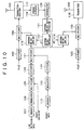
- Fig. 10 is a block diagram showing a structure of a base station where a transmission antenna diversity is employed.
- the base station transmits a synchronous detection pilot signal and user data to a user.
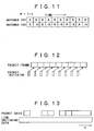
- the synchronous detection pilot signal transmitted to the user includes a first pilot signal (Pilot1) for transmission from an antenna 101 and a second pilot signal (Pilot2) for transmission from an antenna 102.
- the first pilot signal and the second pilot signal are in an orthogonal relationship on the time base, and are transmitted in a known symbol pattern shown in Fig. 11 for example.
- the first pilot signal is diffused in a diffuser 103 into data of, e.g., a 4MHz band in conformity with a diffusion code unique to the base station (sector), and then is supplied to a multiplexer 104.
- the second pilot signal is also diffused in a diffuser 105 into data of, e.g., a 4MHz band in conformity with the same diffusion code as that used for diffusion of the first pilot signal, and then is supplied to a multiplexer 106.
- the user data includes two kinds, i.e., audio or other line switching data and packet data.
- the line switching data are encoded in an encoder 107 for detecting and correcting any error in the wireless propagation path.
- Such encoding process is executed by the use of, e.g., CRC (Cyclic Redundancy Check) in error detection, and a turbo code or a convolutional code in error correction.
- CRC Cyclic Redundancy Check
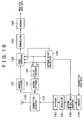
- the line switching data thus encoded are modulated in a modulator 108 by the use of BPSK, QPSK or QAM, and then is supplied to a multiplexer 109. Subsequently the line switching data are temporally multiplexed, in the multiplexer 109, with a packet indicator which indicates, as shown in Fig. 12, the presence or absence of packet channel data and its rate.
- the packet indicator may be mapped independently in some other channel by using another diffusion code.
- the data thus multiplexed are diffused in a diffuser 110 by the diffusion code and the data channel identification code unique to the same base station, and then are supplied to a multiplexer 111.
- the packet data are also encoded in an encoder 112 and then are supplied to a diffuser 114 after being modulated in a modulator 113.
- the packet data are discontinuous differently from the continuous line switching data. Therefore, in accordance with the presence or absence of the data and the packet data rate, the base station changes the value of the aforementioned indicator and inserts the changed value.
- the diffuser 114 diffuses the modulated packet data by using the same diffusion code and packet data channel identification code as those used in the diffuser 103 and unique to the base station, and then supplies the diffused data to the multiplexer 111.
- the multiplexer 111 forms antenna data by multiplexing the line switching data and the packet data diffused in the diffusers 110 and 114 by the respective identification codes, and supplies the antenna data respectively to antenna weight appliers 115 and 116.
- the antenna weight applier 115 multiplies the antenna data by a coefficient for the antenna 101, and supplies the multiplied data to the multiplexer 104. Then the multiplexer 104 multiplexes the multiplied antenna data with the diffused first pilot signal, and supplies the multiplexed data to a transmitter-receiver 117. The transmitter-receiver 117 transmits the antenna data multiplexed with the first pilot signal to the user via the antenna 101.
- the antenna weight applier 116 multiplies the antenna data by a coefficient for the antenna 102, and supplies the multiplied data to the multiplexer 106. Then the multiplexer 106 multiplexes the multiplied antenna data with the diffused second pilot signal, and supplies the multiplexed data to a transmitter-receiver 118. The transmitter-receiver 118 transmits the antenna data multiplexed with the second pilot signal to the user via the antenna 102.
- the antenna data are thus transmitted from the antennas 101 and 102 respectively.
- the base station supplies, to an inverse diffuser 119, the data sent from the user and received by the transmitter-receiver 117 having a receiving function.
- the inverse diffuser 119 executes a process of inverse diffusion of the data received from the user by using the diffusion code unique to the user, and then supplies the processed data to a demodulator 120.
- the demodulator 120 demodulates the data processed through inverse diffusion, and then supplies the demodulated data to an antenna weight data extractor 121.
- the antenna weight data extractor 121 extracts antenna weight data sent from the user per slot (e.g., per 0.667 msec), and supplies the extracted data to an antenna weight controller 122.
- the antenna weight controller 122 maps the received bits and the values of the antenna weight data, and updates the antenna weight values of the antenna weight appliers 115 and 116 in accordance with the mapped values.
- Fig. 14 shows an example of mutual correspondence between the received bits and the antenna weight values. This example assumes a case where 2-bit antenna weight data of "00" to "11" is transmitted per slot from the user's terminal.
- the antenna weight value (w1) of the antenna weight applier 115 is controlled to "1.0"
- the antenna weight value (w2) of the antenna weight applier 116 is controlled to "1.0+j1.0”.
- the antenna weight value (w1) of the antenna weight applier 115 is controlled to "1.0”
- the antenna weight value (w2) of the antenna weight applier 116 is controlled to "-1.0-j1.0".
- the antenna weight value of the antenna weight applier 115 is “w1” and the antenna weight value of the antenna weight applier 116 is “w2" as mentioned, data of a value “w1*S” is outputted from the antenna 101, while data of a value "w2*S” is outputted from the antenna 102.
- Fig. 16 is a block diagram showing a user's terminal device to a base station where a transmission antenna diversity is employed.
- the antenna data transmitted from the base station via the antennas 101 and 102 are received by a transmitter-receiver 131 via the antenna 130 of the user's terminal device, and then are supplied to inverse diffusers 132 and 133.
- the inverse diffuser 132 restores the antenna data by the use of a pilot data diffusion code and supplies the restored data to a pilot decoder 134.
- the pilot decoder 134 estimates the propagation path characteristics H1 and H2 between the antennas 101 and 102 as follows to thereby calculate the estimated values ⁇ and ⁇ of the propagation path characteristics.
- the pilot decoder 134 supplies the estimated values ⁇ and ⁇ of the propagation path characteristics thus calculated to an antenna weight calculator 135 and a phase corrector 136 respectively.
- the antenna weight data inserter 140 inserts the 2-bit antenna weight data through temporal multiplexing into the transmission user data encoded in an encoder 139, so that the transmission user data with the 2-bit antenna weight data attached thereto are transmitted to the aforementioned base station from the antenna 130 via a modulator 141, a diffuser 142 and the transmitter-receiver 131.
- S R*(w1 ⁇ + w2 ⁇ )
- the decode antenna data thus calculated is demodulated in a demodulator 143 and then is decoded in a decoder 144, so that the decoded data is received as user data.
- the explained operation relates to the receiving circuit of merely one channel.
- a group of inverse diffuser 133, phase corrector 136, modulator 143 and decoder 144 may be provided for each of the channels, and the respective operations may be performed in parallel in the plural channels.
- the diffusion code used for inverse diffusion is unique to each relevant channel.
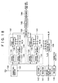
- Fig. 18 is a block diagram showing the structure of a terminal device in a mobile communication system which employs such site diversity.
- the terminal device shown in Fig. 18 represents an example having two-channel receiving circuits 151 and 152 so as to be capable of communicating with two base stations.
- a combiner 153 which combines the decode antenna data obtained from the two-channel receiving circuits 151, 152 and then supplies the combined antenna data to a demodulator 143.
- the receiving circuits 151 and 152 calculate estimated values ⁇ 1, ⁇ 1 and ⁇ 2, ⁇ 2 of the propagation path characteristics respectively between these circuits and the base stations in communication, and then supply the estimated values to an antenna weight calculator 135.
- the antenna weight values selectable by the terminal device need to be selected in consideration of the site diversity gain.
- the receiving circuits 151 and 152 calculate the estimated values ⁇ 1, ⁇ 1 and ⁇ 2, ⁇ 2 of the propagation path characteristics respectively between the antennas.
- the antenna weight calculator 135 selects the antenna weight values w1 and w2 which are the most satisfactory to maximize the received data R obtained according to Eq. 8 given below.
- R (w1(H1-1 + H1-2) + w2(H2-1 + H2-2))*S
- a known diversity receiving device and a control method thereof are disclosed in the International Pamphlet Laid-open No. 97/20400.
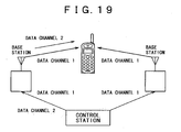
- a channel with a site diversity gain and a channel without any site diversity gain may occasionally be co-existent.
- audio and other line switching data of a data channel 1 are transmitted simultaneously from two base stations to a user's terminal device, while packet data of a data channel 2 are transmitted from only one base station to the user's terminal device.
- An object of the invention resides in providing a wireless transmitter-receiver device which is capable of assigning an optimal antenna weight value to each channel of a terminal conforming to site diversity for communication with a plurality of base stations.
- the present invention selects an optimal antenna weight value in accordance with the quantity of data restored in each receiving circuit or with the state of packet data, and assigns the selected weight value to each receiving circuit.
- the wireless communication device of the present invention is applicable to a cellular or mobile telephone adapted for a mobile communication system employing a site diversity, such as W-CDMA (Wideband Code Division Multiple Access) or CDMA2000.
- a site diversity such as W-CDMA (Wideband Code Division Multiple Access) or CDMA2000.
- audio and other line switching data from plural base stations are transmitted continuously, while packet data from a single base station are transmitted burstily (intermittently).
- the mobile telephone representing the first embodiment of the present invention is so contrived that, when the packet data are existent in the propagation path, the antenna weight value for processing the packet data is selected to be used with regard to the propagation path, but when none of the packet data is existent in the propagation path, the antenna weight value for processing the line switching data is assigned to be used in accordance with the data quantity in each propagation path.
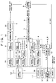
- Fig. 1 shows a block diagram of the mobile telephone representing the first embodiment of the present invention.
- the mobile telephone of this embodiment includes an antenna 1 and a transmitter-receiver 2 for transmission and/or reception of data; a first receiving circuit 3 for restoring line switching data or packet data transmitted from, e.g., a first base station; and a second receiving circuit 4 for restoring line switching data transmitted from a second base station.
- This mobile telephone also has a third receiving circuit 5 used exclusively for restoration of packet data transmitted from one base station, and a combiner 6 for combining the data received by the first and second receiving circuits 3 and 4.
- the mobile telephone further has a demodulator 7 for executing predetermined demodulation of the combined data formed in the combiner 6, and a decoder 8 for decoding the demodulated combined data and outputting the decoded data as received user data.
- the mobile telephone further has a channel monitor 9 for calculating a "weight value” to calculate an "antenna weight value” used in the first receiving circuit 3 for restoration of the packet data, on the basis of the execution data quantity of the received user packet data obtained from the third receiving circuit 5 provided to receive the packet data exclusively, and also for calculating "weight values” to calculate "antenna weight values” used in the first and second receiving circuits 3 and 4 for restoration of the line switching data, on the basis of the respective execution data quantities of the line switching data received by the first and second receiving circuits 3 and 4.
- the mobile telephone further has an antenna weight calculator 10 for calculating an antenna weight value (Rx_W) on the basis of the estimated values of propagation path characteristics (undermentioned ⁇ 1, ⁇ 1, ⁇ 2, ⁇ 2) calculated in the first and second receiving circuits 3 and 4, and also on the basis of the weight values (undermentioned ⁇ 1, ⁇ 2) obtained from the channel monitor 9, and then supplying the antenna weight value (Rx_W) to the first and second receiving circuit 3 and 4; and a transmitting circuit 11 for inserting antenna weight data (Tx_W) of the value obtained from the antenna weight calculator 10, into the data to be transmitted by the user, and then transmitting the entire data to the base station via the transmitter-receiver 2 and the antenna 1.
- Rx_W antenna weight value
- the base station transmits, together with the data, a synchronous detection pilot signal to the mobile telephone so as to perform synchronous detection of the data.
- the first receiving circuit 3 of the mobile telephone has an inverse diffuser 21 for executing a process of inverse diffusion of the received data; a phase corrector 22 for executing a process of phase correction of the inverse-diffused data on the basis of the estimated values ⁇ 1 and ⁇ 1 of the propagation path characteristics obtained from the pilot decoder 24 and also on the basis of the antenna weight value Rx_W obtained from the antenna weight calculator 10; an inverse diffuser 23 for executing a process of inverse diffusion of the synchronous detection pilot signal; and a pilot decoder 24 for calculating the estimated values ⁇ 1 and ⁇ 1 of the propagation path characteristics on the basis of the inverse-diffused synchronous detection pilot signal and then supplying the above estimated values to the phase corrector 22.
- the second receiving circuit 4 has an inverse diffuser 25 for executing a process of inverse diffusion of the received data; a phase corrector 26 for executing a process of phase correction of the inverse-diffused data on the basis of the estimated values ⁇ 2 and ⁇ 2 of the propagation path characteristics obtained from the pilot decoder 28 and also on the basis of the antenna weight value Rx_W obtained from the antenna weight calculator 10; an inverse diffuser 27 for executing a process of inverse diffusion of the synchronous detection pilot signal; and a pilot decoder 28 for calculating the estimated values ⁇ 2 and ⁇ 2 of the propagation path characteristics on the basis of the inverse-diffused synchronous detection pilot signal and then supplying the above estimated values to the phase corrector 26.
- the third receiving circuit 5 used exclusively to receive the packet data has an inverse diffuser 30 for executing a process of inverse diffusion of the received packet data; a phase corrector 31 for executing a process of phase correction of the inverse-diffused packet data; a demodulator 32 for demodulating the phase-corrected packet data; and a decoder 33 for decoding the demodulated packet data and supplying the decoded packet data to the channel monitor 9.
- the transmitting circuit 11 has an encoder 35 for encoding the user data to be transmitted; an antenna weight data inserter 36 for inserting into the encoded user data the antenna weight data (Tx_W) obtained from the antenna weight calculator 10; a modulator 37 for modulating the user data inclusive of the antenna weight data inserted therein; and a diffuser 38 for diffusing the modulated user data by the use of a diffusion code and then transmitting the diffused user data to the base station via the transmitter-receiver 2 and the antenna 1.
- the channel monitor 9 detects the respective execution data quantities of the line switching data restored in the first and second receiving circuits 3 and 4, and then controls the respective antenna weight values, which are used in the receiving circuits 3 and 4, on the basis of the detected execution data quantities.
- the channel monitor 9 detects the execution data quantity of the packet data restored in the third receiving circuit 5 provided to receive the packet data exclusively, and then controls the antenna weight value, which is used in the first receiving circuit 3 for restoration of the packet data, on the basis of the detected execution data quantity of the packet data, and also controls the antenna weight value of the second receiving circuit 4 which restores the line switching data in parallel.
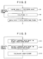
- Fig. 2 is a flowchart showing a flow of the operation performed in the channel monitor 9 to detect the execution data quantity.
- the channel monitor 9 executes, in regard to each of the receiving circuits 3 and 4, the operation of detecting the execution data quantity as shown in the flowchart of Fig. 2.
- the channel monitor 9 detects the total number of the frames used for detection of the total data quantity (num_frame++)
- the channel monitor 9 calculates the execution data quantity of the line switching data in each of the receiving circuits 3 and 4 on the basis of the line switching data restored by the first and second receiving circuits 3 and 4.
- the channel monitor 9 calculates the execution data quantity of the packet data on the basis of the packet data restored by the third receiving circuit 5 provided exclusively for the packet data.
- a flowchart of Fig. 3 shows a flow of the operation to calculate an "antenna weight value".
- the channel monitor 9 detects, at step S11 in the flowchart of Fig. 3, an average rate of the execution data quantities over predetermined plural frames in the first receiving circuit 3. Similarly, at step S12, the channel monitor 9 detects an average rate of the execution data quantities over predetermined plural frames in the second receiving circuit 4.
- Fig. 4 shows an example of the relationship among the line switching data (BTS1 CS instantaneous data) and the packet data (BTS1 PS instantaneous data) transmitted from the first base station (BTS1) and processed in the first receiving circuit 3, and the average rate (BTS1 average data) of the execution data quantities corresponding to the first receiving circuit 3.
- Fig. 5 shows an example of the relationship among the line switching data (BTS2 CS instantaneous data) and the packet data (BTS2 PS instantaneous data) transmitted from the second base station (BTS2) and processed in the second receiving circuit 4, and the average rate (BTS2 average data) of the execution data quantities corresponding to the second receiving circuit 4.
- Figs. 4 and 5 are grounded on an assumption that the line switching data (CS) are transmitted (soft handover) from the first and second base stations at a transmission speed of 12.2 kbps for example, and the packet data (PS) are transmitted (burstily) from each base station at a transmission speed of maximum 384 kbps for example.
- CS line switching data
- PS packet data
- Fig. 4 shows an example where the packet data transmitted from the first base station are processed in the first receiving circuit 3. Therefore, the rate of the line switching data (CS) denoted by a dotted line a in Fig. 4 is kept steady approximately at 10 kbps, but the rate of the packet data (PS) denoted by a thin line b in Fig. 4 appears intermittently in conformity with the rate corresponding to each packet.
- CS line switching data
- PS packet data
- Fig. 5 shows an example where the line switching data transmitted from the second base station are processed in the second receiving circuit 4. In this case, none of packet data is transmitted from the second base station.
- the rate of the line switching data (CS) denoted by a dotted line a in Fig. 5 is kept steady approximately at 12 kbps, but the rate of the packet data (PS) denoted by a thin line b in Fig. 5 is "0 (no data)".
- the rate of the packet data (PS) denoted by a thin line b in Fig. 5 is "0 (no data)".
- the average rate corresponding to the first receiving circuit 3 is expressed as "BTS1_avg_rate”
- the average rate corresponding to the second receiving circuit 4 is expressed as "BTS2_avg_rate”.
- the channel monitor 9 calculates the weight values ⁇ 1 and ⁇ 2 according to the above equations, and then supplies these values to the antenna weight calculator 10.
- Fig. 6 shows examples of the weight values ⁇ 1 and ⁇ 2 thus calculated.
- a dotted line b denotes transition of the weight value ⁇ 2 for the second receiving circuit 4.
- the channel monitor 9 is provided with a minimum operator which adjusts the weight values ⁇ 1 and ⁇ 2 in such a manner that these values calculated according to the above equations do not become "over 0.75, under 0.25" for example.
- the antenna weight calculator 10 selects proper antenna weight values W1 and W2 so that the received data R according to the following equation becomes maximum (in reception strength).
- R ( ⁇ 1W1( ⁇ 1+ ⁇ 1) + ⁇ 2W2( ⁇ 2+ ⁇ 2))*S
- the antenna weight calculator 10 supplies the antenna weight value W1, which has been selected according to the above equation, to the phase corrector 22 of the first receiving circuit 3, and also supplies the antenna weight value W2 to the phase corrector 26 of the second receiving circuit 4. (These processes are represented by Rx_W1 and Rx_W2 in Fig. 1).
- the antenna weight values obtained from the antenna weight calculator 10 are inserted into the transmission user data by the transmitting circuit 11 shown in Fig. 1 and then are fed back to the base station.
- the phase corrector 22 of the first receiving circuit 3 executes a process of phase correction for the data obtained from the inverse diffuser 21, on the basis of the estimated values ⁇ 1, ⁇ 1 of the propagation path characteristics from the pilot decoder 24 and also the antenna weight value W1 of the first receiving circuit 3 from the antenna weight calculator 10.
- phase corrector 26 of the second receiving circuit 4 executes a process of phase correction for the data obtained from the inverse diffuser 21, on the basis of the estimated values ⁇ 2, ⁇ 2 of the propagation path characteristics from the pilot decoder 28 and also the antenna weight value W2 of the second receiving circuit 4 from the antenna weight calculator 10.
- the antenna weight values W1 and W2 supplied to the phase correctors 22 and 26 correspond respectively to the execution data quantities processed in the receiving circuits 3 and 4, thereby optimizing the phases and the amplitudes of the data transmitted from the first and second base stations and restored by the receiving circuits 3 and 4. Consequently, it becomes possible to optimize the phases and the amplitudes of the received user data decoded by the combiner 6, the demodulator 7 and the decoder 8.
- the mobile telephone of the first embodiment detects, in the channel monitor 9, the execution data quantity to be processed by each receiving circuit, and then variably controls the antenna weight value of the data of each receiving circuit on the basis of the execution data quantity thus detected.
- the antenna weight value corresponding to the execution data quantity of the data to be processed in each receiving circuit hence optimizing the phase and the amplitude of the received user data to be restored by each receiving circuit. Consequently, the reception quality can be improved in accordance with the propagation path characteristics that fluctuate temporally.
- the foregoing mobile telephone of the first embodiment is capable of variably controlling the antenna weight values on the basis of the execution data quantities of the data processed by the receiving circuits 3 and 4.
- the mobile telephone of this second embodiment is so contrived as to variably control the antenna weight values of the receiving circuits 3 and 4 in accordance with "the state of the packet data".
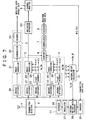
- the mobile telephone of the second embodiment has an indicator extractor 50, as shown in Fig. 7.
- this indicator extractor 50 Upon reception of the packet data, this indicator extractor 50 inputs the data from a first receiving circuit which executes a process of restoring the packet data.
- the data indicating the state of the packet data and outputted from the indicator extractor 50 is supplied to a channel monitor 9.
- any component parts identical in operation with those in the foregoing mobile telephone of the first embodiment are denoted by the same reference numerals or numerals. Therefore, with regard to any component parts denoted in Fig. 7 by the same reference numerals or symbols as those in the mobile telephone of the first embodiment, refer to the explanation given already in connection with the aforementioned first embodiment.
- the indicator extractor 50 extracts the indicator from the received packet data and then supplies the indicator to the channel monitor 9.
- the decoder 33 of the third receiving circuit 5 forms a flag which signifies as to whether the input packet data have been properly received (decoded) or not, and then supplies the flag to the channel monitor 9.
- the channel monitor 9 Upon detection of the reception of the packet data according to the indicator, the channel monitor 9 sets a predetermined great value to the weight value ⁇ 1 for evaluating the antenna weight value W1 used in the receiving circuit (in this case, the first receiving circuit 3) which processes the packet data.
- the channel monitor 9 holds, at the predetermined great value, the weight value ⁇ 1 for evaluating the antenna weight value to process the packet data, during a predetermined time period after detection of the reception of the packet data according to the indicator.
- a request for re-transmission of the packet data is sent from the mobile telephone to the base station, and then the packet data not received properly are re-transmitted from the base station to the mobile telephone.
- the channel monitor 9 extends, under control, the time period to hold the weight value ⁇ 1 in preparation for the packet data to be re-transmitted from the base station (i.e., for the packet data not received properly), and holds the weight value ⁇ 1 for more than a predetermined time period.
- a flowchart of Fig. 8 shows a flow of the operation performed by the channel monitor 9.
- the operation starts when a main power source of the mobile telephone is turned on.
- the channel monitor 9 makes a decision as to whether any indicator supplied from the indicator extractor 50 is existent or not, thereby executing a detection as to whether the packet data have been received or not.
- the channel monitor 9 makes a decision at step S22 as to whether the time is over or not. That is, since the packet data are transmitted intermittently from the base station as described, the channel monitor 9 starts to clock the packet data at the timing of the reception by means of a timer (step S26), and holds the weight value ⁇ 1 during a predetermined time period (e.g., several seconds) clocked by the timer.
- a timer e.g., several seconds
- the channel monitor 9 makes a decision as to whether the predetermined time period clocked by the timer has elapsed or not after a detection of the absence of the packet data.
- the antenna weight calculator 10 calculates the antenna weight values W1 and W2 on the basis of the weight values ⁇ 1 and ⁇ 2 in a manner to execute the data processing that weights the line switching data in the receiving circuits 3 and 4.
- the channel monitor 9 holds, at step S25, the preceding weight value ⁇ 1 at the predetermined great value of 0.75 for example as a weight value to calculate the antenna weight values W1 and W2 for the packet data.
- the antenna weight calculator 10 calculates the antenna weight values W1 and W2 on the basis of the weight values ⁇ 1 and ⁇ 2 in a manner to execute the data processing that weights the packet data in the receiving circuits 3 and 4.
- the channel monitor 9 starts the timer, at step S26, to clock the predetermined time period upon detection of the packet data.
- the channel monitor 9 sets, as the weight value ⁇ 1, a predetermined great value (a2) such as, e.g., 0.75 for the packet data, and then supplies the weight value ⁇ 1 to the antenna weight calculator 10.
- a2 a predetermined great value
- the channel monitor 9 makes a decision as to whether proper reception of the packet data has been performed or not on the basis of the flag obtained from the decoder 33 of the third receiving circuit 5 which executes restoration of the packet data.
- the channel monitor 9 sets, at step S24, the weight value ⁇ 2 corresponding to the weight value ⁇ 1 set at step S25, and then supplies these values to the antenna weight calculator 10.
- a request for re-transmission of the packet data is sent from the mobile telephone to the base station as mentioned. It is highly probable that, in response to such a request for re-transmission, the packet data will be transmitted immediately from the base station.
- the channel monitor 9 extends the preset clock time period of the timer by a predetermined length. Accordingly, upon re-transmission of the packet data from the base station, the re-transmitted packet data can be processed according to the optimal weight value ⁇ 1.
- FIG. 9 shows diagrams showing how the weight values ⁇ 1 and ⁇ 2 are variably controlled as described. Out of these diagrams, (a) of Fig. 9 shows the weight value ⁇ 1 set by the channel monitor 9; (b) of Fig. 9 shows the timing to receive the packet data; (c) of Fig. 9 shows the timing to supply the detected indicator from the indicator extractor 50 to the channel monitor 9; and (d) of Fig. 9 shows the timing to supply a flag, which is indicative of a reception error, from the decoder 33 to the channel monitor 9 when any reception error has been caused in the packet data.
- the packet data are first received at time t1 as shown in (b) of Fig. 9, and the indicator extracted by the decoder 33 at the timing of such reception is then supplied to the channel monitor 9.
- the channel monitor 9 holds the packet data weight value a2 for a predetermined period from time t1 to time t2.
- the channel monitor 9 changes the packet data weight value from a2 to a1 at the timing of such expiration, and supplies the weight value a1 to the antenna weight calculator 10.
- the channel monitor 9 changes the packet data weight value again to a2 at the timing of reception of the packet data and supply of the indicator, and then supplies the weight value a2 to the antenna weight calculator 10.
- the channel monitor 9 Upon reception of the packet data at time t3 in (b) of Fig. 9, the channel monitor 9 supplies the weight value a2 to the antenna weight calculator 10 for a predetermined period from time t3 to time t5 in (a) of Fig. 9. However, if a flag indicative of a reception error is supplied, the channel monitor 9 extends the time period predetermined to hold the weight value a2, i.e., from time t5 to time t7 as shown in (a) of Fig. 9.
- the packet data re-transmitted due to the occurrence of a reception error can be received within the extended time period as denoted by time t6 in (b) of Fig. 9, whereby the data can be processed according to the optimal weight value a2.
- the mobile telephone of the second embodiment selectively changes, under control, the weight values ⁇ 1 and ⁇ 2 supplied to the antenna weight calculator 10, in accordance with the states of the packet data (the presence or absence of the packet data, the possibility of receiving the packet data, any reception error regarding the packet data, etc.).
- the weight value for processing the packet data or the weight value for processing the line switching data may be used selectively in accordance with the aforementioned states of the packet data.
- the weight value ⁇ 1 is implied to have a concrete numerical value such as 0.6 or 0.75, but this value may be set adaptively in conformity with the design and so forth.
- the present invention is capable of assigning an optimal antenna weight value to each channel of a user's terminal device adapted for a site diversity to communicate with a plurality of base stations, thereby achieving improvement in the reception characteristics of the terminal device.
Landscapes
- Engineering & Computer Science (AREA)
- Computer Networks & Wireless Communication (AREA)
- Signal Processing (AREA)
- Physics & Mathematics (AREA)
- Mathematical Physics (AREA)
- Mobile Radio Communication Systems (AREA)
- Radio Transmission System (AREA)
Applications Claiming Priority (3)
| Application Number | Priority Date | Filing Date | Title |
|---|---|---|---|
| JP2002324555A JP4082666B2 (ja) | 2002-11-07 | 2002-11-07 | 無線受信装置 |
| JP2002324555 | 2002-11-07 | ||
| PCT/JP2003/013704 WO2004042961A1 (ja) | 2002-11-07 | 2003-10-27 | 無線送受信装置 |
Publications (3)
| Publication Number | Publication Date |
|---|---|
| EP1560351A1 true EP1560351A1 (de) | 2005-08-03 |
| EP1560351A4 EP1560351A4 (de) | 2011-03-09 |
| EP1560351B1 EP1560351B1 (de) | 2015-09-02 |
Family
ID=32310450
Family Applications (1)
| Application Number | Title | Priority Date | Filing Date |
|---|---|---|---|
| EP03758936.3A Expired - Lifetime EP1560351B1 (de) | 2002-11-07 | 2003-10-27 | Funksende-/empfangs vorrichtung |
Country Status (6)
| Country | Link |
|---|---|
| US (1) | US7200422B2 (de) |
| EP (1) | EP1560351B1 (de) |
| JP (1) | JP4082666B2 (de) |
| KR (1) | KR101002077B1 (de) |
| CN (1) | CN100431284C (de) |
| WO (1) | WO2004042961A1 (de) |
Families Citing this family (3)
| Publication number | Priority date | Publication date | Assignee | Title |
|---|---|---|---|---|
| US8737361B2 (en) * | 2006-07-07 | 2014-05-27 | Samsung Electronics Co., Ltd. | Method and apparatus for transmitting signal in communication system |
| JP5367843B2 (ja) * | 2009-12-16 | 2013-12-11 | 株式会社東芝 | 無線信号処理装置及び無線装置 |
| US8595430B2 (en) | 2010-09-30 | 2013-11-26 | International Business Machines Corporation | Managing a virtual tape library domain and providing ownership of scratch erased volumes to VTL nodes |
Family Cites Families (9)
| Publication number | Priority date | Publication date | Assignee | Title |
|---|---|---|---|---|
| US5559522A (en) * | 1994-07-25 | 1996-09-24 | Motorola, Inc. | Antenna positioning apparatus capable of substantially vertical orientation |
| JPH0865201A (ja) * | 1994-08-18 | 1996-03-08 | Matsushita Electric Ind Co Ltd | 移動通信装置 |
| JP2785812B2 (ja) * | 1995-07-19 | 1998-08-13 | 日本電気株式会社 | Fdd/cdma送受信システム |
| EP0807989B1 (de) * | 1996-05-17 | 2001-06-27 | Motorola Ltd | Verfahren und Vorrichtung zur Gewichtung eines Uebertragungsweges |
| JP3641961B2 (ja) * | 1999-02-01 | 2005-04-27 | 株式会社日立製作所 | アダプティブアレイアンテナを使用した無線通信装置 |
| JP2001111464A (ja) * | 1999-10-08 | 2001-04-20 | Matsushita Electric Ind Co Ltd | 基地局装置及び無線送信方法 |
| KR100689398B1 (ko) * | 1999-10-09 | 2007-03-08 | 삼성전자주식회사 | 이동통신시스템에서 폐루프 송신 안테나 다이버시티 장치 및 방법 |
| JP4176463B2 (ja) * | 2000-08-10 | 2008-11-05 | 富士通株式会社 | 送信ダイバーシチ通信装置 |
| JP2002198875A (ja) | 2000-12-22 | 2002-07-12 | Nippon Soken Inc | Cdma方式の通信端末 |
-
2002
- 2002-11-07 JP JP2002324555A patent/JP4082666B2/ja not_active Expired - Fee Related
-
2003
- 2003-10-27 US US10/499,203 patent/US7200422B2/en not_active Expired - Fee Related
- 2003-10-27 CN CNB2003801001618A patent/CN100431284C/zh not_active Expired - Fee Related
- 2003-10-27 WO PCT/JP2003/013704 patent/WO2004042961A1/ja not_active Ceased
- 2003-10-27 KR KR1020047010167A patent/KR101002077B1/ko not_active Expired - Fee Related
- 2003-10-27 EP EP03758936.3A patent/EP1560351B1/de not_active Expired - Lifetime
Also Published As
| Publication number | Publication date |
|---|---|
| US20050085268A1 (en) | 2005-04-21 |
| EP1560351B1 (de) | 2015-09-02 |
| CN1685642A (zh) | 2005-10-19 |
| JP4082666B2 (ja) | 2008-04-30 |
| KR20050055622A (ko) | 2005-06-13 |
| JP2004159200A (ja) | 2004-06-03 |
| KR101002077B1 (ko) | 2010-12-17 |
| CN100431284C (zh) | 2008-11-05 |
| EP1560351A4 (de) | 2011-03-09 |
| US7200422B2 (en) | 2007-04-03 |
| WO2004042961A1 (ja) | 2004-05-21 |
Similar Documents
| Publication | Publication Date | Title |
|---|---|---|
| US7515563B2 (en) | Communications systems | |
| US6549525B2 (en) | High data rate CDMA wireless communication system | |
| US6625138B2 (en) | Data transmission method and a radio system | |
| US20090147834A1 (en) | Radio communication apparatus | |
| US9130616B2 (en) | Weighting factor reporting method in a mimo mobile communications system, and base station and user apparatus that are suitable for use in the method | |
| EP1147622A2 (de) | Verfahren und einrichtung zur sendeleistungssteuerung in einem kommunikationssystem mit kodemultiplex-vielfachzugriff | |
| WO2004004164A1 (ja) | 送信電力制御方法及び基地局装置 | |
| WO2004073205A2 (en) | Power control for reverse packet data channel in cdma systems | |
| US6480554B1 (en) | Channel estimation in a CDMA cellular communication system | |
| JP2001522176A (ja) | 無線通信システムにて無線インターフェースを介してデータを伝送する方法及び装置 | |
| EP1413069B1 (de) | Diversität-empfangskombinator mit wählbarer phaseninversion und variabler verstärkung | |
| US20050227732A1 (en) | Base station for radio communication, radio communication method and mobile station | |
| CN1913389B (zh) | 移动通信系统的控制方法、控制装置、移动通信系统 | |
| JP2012186840A (ja) | 二次局及び該二次局を動作させる方法 | |
| EP1560351A1 (de) | Funksende-/empfangs vorrichtung | |
| EP1677553A1 (de) | Übertragungsgerät und verstärkungsregelungsverfahren | |
| WO2006043245A1 (en) | System and method of operating a mimo system | |
| US20020167993A1 (en) | Cdma receiving device and error correction method | |
| CN101558580A (zh) | 移动站及移动站中的天线校验控制方法 | |
| JP2005269071A (ja) | 無線基地局の評価方法及び装置 | |
| JP2004235674A (ja) | 送信ウェイト制御装置、送信ウェイト制御方法及び無線基地局 |
Legal Events
| Date | Code | Title | Description |
|---|---|---|---|
| PUAI | Public reference made under article 153(3) epc to a published international application that has entered the european phase |
Free format text: ORIGINAL CODE: 0009012 |
|
| 17P | Request for examination filed |
Effective date: 20050511 |
|
| AK | Designated contracting states |
Kind code of ref document: A1 Designated state(s): AT BE BG CH CY CZ DE DK EE ES FI FR GB GR HU IE IT LI LU MC NL PT RO SE SI SK TR |
|
| RBV | Designated contracting states (corrected) |
Designated state(s): DE FR GB |
|
| A4 | Supplementary search report drawn up and despatched |
Effective date: 20110203 |
|
| 17Q | First examination report despatched |
Effective date: 20110511 |
|
| RAP1 | Party data changed (applicant data changed or rights of an application transferred) |
Owner name: SONY MOBILE COMMUNICATIONS JAPAN, INC. |
|
| REG | Reference to a national code |
Ref country code: DE Ref legal event code: R079 Ref document number: 60347995 Country of ref document: DE Free format text: PREVIOUS MAIN CLASS: H04B0007260000 Ipc: H04B0007020000 |
|
| RIC1 | Information provided on ipc code assigned before grant |
Ipc: H04B 7/08 20060101ALI20150206BHEP Ipc: H04B 7/06 20060101ALI20150206BHEP Ipc: H04B 7/02 20060101AFI20150206BHEP |
|
| GRAP | Despatch of communication of intention to grant a patent |
Free format text: ORIGINAL CODE: EPIDOSNIGR1 |
|
| INTG | Intention to grant announced |
Effective date: 20150413 |
|
| GRAS | Grant fee paid |
Free format text: ORIGINAL CODE: EPIDOSNIGR3 |
|
| GRAA | (expected) grant |
Free format text: ORIGINAL CODE: 0009210 |
|
| AK | Designated contracting states |
Kind code of ref document: B1 Designated state(s): DE FR GB |
|
| REG | Reference to a national code |
Ref country code: GB Ref legal event code: FG4D |
|
| REG | Reference to a national code |
Ref country code: DE Ref legal event code: R096 Ref document number: 60347995 Country of ref document: DE |
|
| REG | Reference to a national code |
Ref country code: FR Ref legal event code: PLFP Year of fee payment: 13 |
|
| PGFP | Annual fee paid to national office [announced via postgrant information from national office to epo] |
Ref country code: GB Payment date: 20151021 Year of fee payment: 13 Ref country code: DE Payment date: 20151022 Year of fee payment: 13 |
|
| PGFP | Annual fee paid to national office [announced via postgrant information from national office to epo] |
Ref country code: FR Payment date: 20151023 Year of fee payment: 13 |
|
| REG | Reference to a national code |
Ref country code: DE Ref legal event code: R097 Ref document number: 60347995 Country of ref document: DE |
|
| PLBE | No opposition filed within time limit |
Free format text: ORIGINAL CODE: 0009261 |
|
| STAA | Information on the status of an ep patent application or granted ep patent |
Free format text: STATUS: NO OPPOSITION FILED WITHIN TIME LIMIT |
|
| 26N | No opposition filed |
Effective date: 20160603 |
|
| REG | Reference to a national code |
Ref country code: DE Ref legal event code: R119 Ref document number: 60347995 Country of ref document: DE |
|
| GBPC | Gb: european patent ceased through non-payment of renewal fee |
Effective date: 20161027 |
|
| REG | Reference to a national code |
Ref country code: FR Ref legal event code: ST Effective date: 20170630 |
|
| PG25 | Lapsed in a contracting state [announced via postgrant information from national office to epo] |
Ref country code: DE Free format text: LAPSE BECAUSE OF NON-PAYMENT OF DUE FEES Effective date: 20170503 Ref country code: FR Free format text: LAPSE BECAUSE OF NON-PAYMENT OF DUE FEES Effective date: 20161102 Ref country code: GB Free format text: LAPSE BECAUSE OF NON-PAYMENT OF DUE FEES Effective date: 20161027 |