EP1560473A2 - Méthode et dispositif pour alimenter des lampes à haute pression en mode de résonance longitudinal - Google Patents
Méthode et dispositif pour alimenter des lampes à haute pression en mode de résonance longitudinal Download PDFInfo
- Publication number
- EP1560473A2 EP1560473A2 EP04030344A EP04030344A EP1560473A2 EP 1560473 A2 EP1560473 A2 EP 1560473A2 EP 04030344 A EP04030344 A EP 04030344A EP 04030344 A EP04030344 A EP 04030344A EP 1560473 A2 EP1560473 A2 EP 1560473A2
- Authority
- EP
- European Patent Office
- Prior art keywords
- frequency
- lamp
- impedance
- operating method
- ami
- Prior art date
- Legal status (The legal status is an assumption and is not a legal conclusion. Google has not performed a legal analysis and makes no representation as to the accuracy of the status listed.)
- Granted
Links
Images






Classifications
-
- H—ELECTRICITY
- H01—ELECTRIC ELEMENTS
- H01J—ELECTRIC DISCHARGE TUBES OR DISCHARGE LAMPS
- H01J61/00—Gas-discharge or vapour-discharge lamps
- H01J61/82—Lamps with high-pressure unconstricted discharge having a cold pressure > 400 Torr
- H01J61/827—Metal halide arc lamps
-
- H—ELECTRICITY
- H05—ELECTRIC TECHNIQUES NOT OTHERWISE PROVIDED FOR
- H05B—ELECTRIC HEATING; ELECTRIC LIGHT SOURCES NOT OTHERWISE PROVIDED FOR; CIRCUIT ARRANGEMENTS FOR ELECTRIC LIGHT SOURCES, IN GENERAL
- H05B41/00—Circuit arrangements or apparatus for igniting or operating discharge lamps
- H05B41/14—Circuit arrangements
- H05B41/26—Circuit arrangements in which the lamp is fed by power derived from DC by means of a converter, e.g. by high-voltage DC
- H05B41/28—Circuit arrangements in which the lamp is fed by power derived from DC by means of a converter, e.g. by high-voltage DC using static converters
- H05B41/288—Circuit arrangements in which the lamp is fed by power derived from DC by means of a converter, e.g. by high-voltage DC using static converters with semiconductor devices and specially adapted for lamps without preheating electrodes, e.g. for high-intensity discharge lamps, high-pressure mercury or sodium lamps or low-pressure sodium lamps
- H05B41/292—Arrangements for protecting lamps or circuits against abnormal operating conditions
- H05B41/2928—Arrangements for protecting lamps or circuits against abnormal operating conditions for protecting the lamp against abnormal operating conditions
-
- Y—GENERAL TAGGING OF NEW TECHNOLOGICAL DEVELOPMENTS; GENERAL TAGGING OF CROSS-SECTIONAL TECHNOLOGIES SPANNING OVER SEVERAL SECTIONS OF THE IPC; TECHNICAL SUBJECTS COVERED BY FORMER USPC CROSS-REFERENCE ART COLLECTIONS [XRACs] AND DIGESTS
- Y02—TECHNOLOGIES OR APPLICATIONS FOR MITIGATION OR ADAPTATION AGAINST CLIMATE CHANGE
- Y02B—CLIMATE CHANGE MITIGATION TECHNOLOGIES RELATED TO BUILDINGS, e.g. HOUSING, HOUSE APPLIANCES OR RELATED END-USER APPLICATIONS
- Y02B20/00—Energy efficient lighting technologies, e.g. halogen lamps or gas discharge lamps
Definitions
- the invention relates to an operating method, electronic ballast and system for the resonance mode of high-pressure lamps in the longitudinal mode according to The preamble of claim 1.
- These are in particular high-pressure discharge lamps with ceramic discharge vessel, preferably with a Aspect ratio of at least 1.5.
- the invention is based on the further object of using a metal halide lamp high color rendering and increased light output operate so that their Brennlage no restriction is subject. At most there should be a small difference the operating data between horizontal and vertical burning position result.
- Another object is to provide an electronic ballast that perform an automated procedure as possible to impose an appropriate Amplitude modulation with AM degree AMI near a longitudinal acoustic Resonance for different focal positions approximately the same color rendering and to achieve luminous efficacy.
- Another object is a sought acoustic resonance, preferably the second longitudinal, reliable in any burning position.
- Another task is to specify an associated system for it.
- Another task is while the operation of high-efficiency high-pressure lamps optimum resonance frequency setting to determine for a mixture of the metal halide plasma and adjust.
- Another task is to specify an algorithm with which of lamp operation a ballast for the mixture of metal halide plasma optimal frequency setting of the mixing acoustic resonance determined and reproducible sets.
- the operating method according to the invention is geared to this, from the outset always a certain frequency, preferably near the second longitudinal Resonance of the horizontal burning position, to stimulate continuous use, because with it optimal mixing of the filling components, especially the metal halides, can also be achieved in non-horizontal burning position. Thus, color effects and color scattering largely avoided.
- This frequency must be delayed after Maintaining a certain grace period will be imprinted on the system.
- This approach allows a reliable swing close to the optimum Resonance, in particular the second longitudinal acoustic resonance f002 of horizontal burning position.
- the process is mainly in ceramic high-pressure lamps suitable with an aspect ratio (length: diameter) of at least 1.5, preferably ⁇ 2 (typically 3 to 6). It uses an HF sweep operation, which means the segregation is suppressed and the mixing of the metal halide arc plasma is improved.
- the location of the resonance f002 in horizontal burning position is for an individual Lamp determined first. This can be done in advance through various procedures or again on-line in the operation of the lamp done, z. B. by measuring the Lamp impedance during operation with rectangular current impression and superimposed sinusoidal signal, for example, the amplitude of the sinusoidal component about 5-15% of the current amplitude with variation of the frequency of the sine wave signal should be.
- the inside length IL is typically ⁇ 1% x IL.
- the inside length represents that dimension the lamp that defines the second longitudinal acoustic resonance, which for optimal mixing of the arc plasma, especially in vertical Burning position, needs to be stimulated.
- the geometry is cylindrical with straight or bevelled ends, but also bulbous vessels are suitable. In such cases, instead of a geometrically determined inside length, an effective Inner length can be assumed.
- Deviations of the effective Sonic speeds compared to Hg / Ar buffer gas mixtures of about 15 to 20% found the mixed operation.
- a concrete reading was e.g. at 550 m / s compared to 464 m / s.
- the sweep operation preferably ramped with increasing or decreasing frequency executed.
- This mode uses the effect of arc stabilization on the central axis of the discharge vessel in the vertical as well as in the horizontal burning position Excitation of centering gas oscillations around the bow core.
- This basic current signal form becomes, possibly after a waiting period (Warming up the lamp), also an amplitude modulation AM imprinted, whose fundamental frequency is the second longitudinal resonance f002hor in horizontal Burning position is. this fundamental frequency is the starting point of the control.
- the frequency fSW can be in the range of the first azimuthal and radial resonance f100 and f010 are chosen, preferably near their mean with a deviation up to to 10%, ie 10% x (f100 + f010) / 2).
- Prerequisite for a procedure for setting the AM frequency for optimal Mixing of the arc plasma in each burning position is first the determination and storing the location of the second longitudinal resonance frequency f002 in FIG practically always already mixed horizontal burning position.
- To set a Basic operation with this frequency must first individually for each lamp
- a procedure for settling in the best mixed mixed operating condition thereby realize that after the Igniting the arc discharge, while maintaining a warm-up (waiting time to Time t1) of about 30 to 80 seconds, preferably about 60 seconds, within an embossing phase from approx. 60 to 150 sec, the fundamental frequency fAM of the amplitude modulation AM is set to a value of 1.15 to 1.25 times the frequency f002_hor becomes.
- the AM frequency can be chosen arbitrarily, but is preferred f002_hor default.
- the AM degree can previously be arbitrary in one area be set from 0 to 25%.
- the AM degree is set to 15 to 30%.
- P refers while the amplitude modulation is about 15-25% amplitude modulation set.
- the fundamental solution consists in the controlled recognition of the optimal frequency point fopt of the AM and the appropriate signal level AMI of the AM degree for the mixing of the metal halide plasma one by means of acoustic longitudinal Resonance controlled metal halide discharge lamp and the provision an electronic ballast for operation in optimally mixed Mode.
- the AM degree is a measure of the respective electrical power, based on the total power, which is converted into the excitation of longitudinal resonances.
- the behavior of the lamp impedance Z (fAM) as a function of the frequency fAM over the frequency range ⁇ F is recorded as a function of the AM degree and saved as a characteristic field. It shows up with an increase in the AM degree first one and then two, and even several consecutive as a function of fAM dynamic extremema of the lamp impedance, which in the course of the Gradually increasing and increasing the degree of AM education.
- the power signal level of a mixing of the metal halides serve discharge-controlling signal frequency, for example, the Signal level of a linear overlay, which is a mixed longitudinal-azimuthal Resonance causes a similar increased mixing of the arc plasma causes like the second longitudinal resonance.
- the process is divided into several steps and consists of at least two Steps.
- the first step is a successive scanning (scanning) of a relatively large frequency interval the amplitude modulation (fAM).
- the scan area is between an upper starting point ST and a lower end point SP, so that the frequency of the frequency start point ST is above the end point SP.
- this frequency interval is [ST, SP] for a Geometry with given inner diameter ID and given inner length IL and a given Metallhalogenid sleepllung already once determined in principle and stored in the associated electronic ballast.
- Typical should be both ST and SP are each preferably at least 10 -15% outside of of FM1 and FM2 are located (ST ⁇ 1.10 * FM1, SP ⁇ 0.9 * FM2).
- the desired value can be in the lamp system, consisting of lamp and electronic Ballast, be preprogrammed or specified as input command become.
- a typical interval width of the scan area ST-SP for the first step is about 8-15 kHz.
- the discharge vessel of the lamp has a Internal dimension of 19 mm in length and an inner diameter of 4 mm
- the buffer gas is a mixture of Hg-argon.
- FM1 is thus 25 kHz
- FM2 is 22 kHz.
- a complete characterization of Z as a function of time is optimal Setting not necessary. It is sufficient as a minimum requirement a measurement in the desired burning position, in particular vertically, with a one-time complete Driving over the frequency range FM is sufficient between the limits FM1 and FM2, in which the mixing occurs. Preference is given to safety a larger frequency window between the frequency start point ST and the frequency end point SP, because at the end point SP no significant plasma mixing, or at the upper frequency point ST possibly a small plasma mixture is present.
- the procedure described uses the with increasing frequency shift gradually improved mixing of the metal halides in the plasma to characteristic Frequencies, ie in particular the resonance frequency f002, for the mixing process to investigate. It turns out that preferably a constant rate of Frequency shift (frequency scan) should be chosen, taking care of it Find an optimal speed in the order of 0.1 to 0.5 kHz / sec leaves the normal lamp operation. It is also recommended that the procedure is applied only after a warm-up phase of about 1 to 3 minutes becomes.
- the changed temperature profile of the gas discharge both change axially and radially and thus also the isotherm of the discharge vessel change.
- the heat capacity of the discharge vessel must be sufficient slow adaptation to the new conditions in the plasma to reach the thermal equilibrium. This requires depending on the shape and Volume of the discharge vessel for different lengths of time.
- the signal level used is the AM degree AMI.
- Umax and Umin is the maximum and minimum burning voltage.
- the value of AMI becomes so long for the determination of the optimal acoustic plasma mixture gradually increases until the lamp impedance during the driving through of the mixing Frequency range FM instead of a single maximum at least two distinct, characteristic maxima ZMAX1 and ZMAX2 shows, between those an impedance minimum ZMIN is.
- the amount of the lamp impedance am best compared to the almost non-mixed state Zrel, used, ie Z (fAM) ⁇
- the degree of modulation AMI becomes stepwise Increased and always kept a constant scan of the AMI mixing frequency interval [ST, SP] performed until the characteristic Show impedance changes of the function Z (fAM).
- the degree of modulation can be AMI, typically starting at a value of approx. 5-10%, in steps of approx. 2-5% are increased, so that on average about 4 to 12 passes are needed.
- One sufficient maximum value of the AM degree is usually between 20 and 40%.
- the characteristic of the change of the impedance Z at the frequency fAM reached an extreme point, so that the value dZ (fAM) / dfAM a negative minimum reached.
- An evaluation of the impedance characteristic according to this criterion may also be beneficial in determining the determination of the lower AM frequency FM2 be used for the plasma mixture.
- step 2 For this a step 2 is applied:
- AMI shift rate of the function FM2
- AMI shift rate of the function FM2
- step 2 With the AM index AMlopt set in step 2 is now starting from ST or at least from FM1 towards FM2 the AM frequency fAM with comparable Frequency change rate as in step 1 (typ.0.1-0.5kHz / sec) up to one frequency point fAMopt driven at the frequency point of the minimum (more generally: of the inverse extremum) of the impedance change FM2 ⁇ FMmin ⁇ FM1.
- the remedy here is to adjust to a slightly higher frequency.
- the distance between the lower limit frequency FM2 and FMmin depends on the AM degree Consequently, it can be adjusted to some extent using the AM degree become.
- the generation of the characteristic field with the characteristic signal levels AMI as well as with the characteristic frequencies and the determination of the cutoff frequencies (ST, SP, FM1,2) for acoustic plasma mixture, in particular by the second longitudinal resonance, is typically only after the lamp start, ie 1 to 3 minutes after lamp start, with a frequency shift rate of 100 Hz / s to 1 kHz / s (AM or HF) with a step size (resolution) of 100 to 200 Hz performed. This measurement can be done once after the first lamp start or repeatedly at regular intervals or at each lamp start be performed.
- the starting point is the lower impedance maximum ZMAX2 with frequency FM2 used, or even located within the mixing area Frequency by at least 150 Hz, preferably at least 200 Hz, higher as FM2 lies. This frequency is then increased in increments of 50 to 150 Hz and measure the lamp impedance. After a transient period of at least 1 min, the lamp impedance is again at the previously scanned Frequency points measured and recorded, for example, in one nonvolatile memory in which the data is controlled by a microprocessor be stored.
- the impedance curve between impedance maximum ZMAX at the frequency FM2, below which plasma interference no longer occurs, and the upstream impedance minimum ZMIN used at a slightly higher frequency FMmin is selected.
- step 4 After reaching the range by step 3, a step 4 is thus performed.
- a preferred optimal frequency point fopt is from the range between the point FMmin and the point FM2 + 1 / 5x (FM2-FMmin).
- the frequency point fopt found thereby has substantially the same Properties such as the frequency point FMmin, which in slowly performed Scan the lamp impedance a local minimum of the relative impedance change shows and thereby as optimal frequency point for a lasting balance the mixing is excellent.
- the lamp power is controlled by the ballast (eg for the purpose of Dimming), is again the whole after setting a different lamp power Repeat measurement to set the optimal frequency point for the new to determine the set lamp parameters.
- This power adjustment can be achieved by known characteristics of the lamp characteristics, which have already been determined by the manufacturer and possibly in the electronic Ballast already stored, according to the above principle below Perception of shortcuts with significantly less time than at the first measurement.
- the entire procedure can be independent of a programmed electronic Ballast, which is controlled by a microprocessor to be performed and also allows the adaptation of the relevant operating parameters for different ones Lamp types (for example, different color temperature) of a lamp power to. The same applies to the same lamp types with not too different Lamp power.
- This is a single electronic ballast for HF operation of multiple lamp types, with operational stabilization using longitudinal acoustic resonance modes, preferred the second acoustic resonance.
- this technology also allows the Setting different color temperatures for a lamp, for example, by different acoustic resonance modes are excited.
- the invention also includes combinations of the methods described above and the implementation of the method in a ballast.
- the specified periods can due to a temporarily increased power input directly after the start of the arc discharge be shortened by up to 50%.
- the above can Period when used for discharge vessels with particularly high heat capacity can also be increased up to 200%.
- the measuring steps for determining the frequency fAM and the Undergo AM degrees several times.
- characteristics for certain combinations of lamp geometry and filling system in the electronic ballast be preprogrammed, so that an abbreviated Method can be used only by using individual substeps can.
- a start or shutdown criterion for the high-pressure lamp type to be operated be set defined.
- the invention also includes electronic ballasts with microprocessors in which the described procedures are implemented.
- Fig. 1 is a schematic representation of a high-pressure lamp with a relatively high Aspect ratio ID / IL shown. It uses a cylindrical discharge vessel. 1 made of ceramic, with a given inner diameter ID and given inner length IL. At the ends 2 of the discharge vessel electrodes 3 are arranged, which are connected by means of bushings 4 with external power supply lines 5.
- the Discharge vessel typically contains a filling of buffer gas Hg with argon and metal halides, for example, a mixture of alkali and rare earth iodides and thallium.
- the lamp is connected to an electronic ballast, see Figure 8, operated at high frequency in acoustically stabilized resonance. For that has especially the second longitudinal resonance is recommended.
- the closer examined lamp is a high efficient 70W metal halide lamp Power.
- the discharge vessel has a maximum axial inner length IL of 18.7 mm and an inside diameter ID of 4 mm.
- the aspect ratio is 4.7.
- the electrode distance is 14.8 mm.
- the vertical burning position shows after the start of operation and a warm-up 120 sec of a segregated, ie unmixed metal halide along of the bow.
- the portion of the metal halides in the vapor phase is not evenly distributed over the arc length.
- the emission of the alkali and SE-iodides concentrates in the lower third of the lamp, while in the upper part to the upper Electrode mainly emission of Hg and TI is observed.
- the lamp has a relatively low color rendering and a relatively low Light output.
- the color temperature in the vertical burning position differs significantly from the horizontal burning position, namely to to 1500 K.
- This range is assumed to be the outermost frequency range, which is now in another procedure of a sequence of frequency scans of AM with stepwise Increasing the degree of AM is more limited.
- the frequency FM1 of 27 kHz, at which in this embodiment at low AM degree the only maximum ZMAX1 of the lamp impedance occurs, is now according to FIG. 3b embedded in a narrower interval of, for example, 10 kHz width, that by a start frequency ST (30 kHz) and an end frequency SP (20 kHz) is determined.
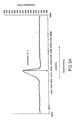
- FIG. 3b shows the principle by suddenly increasing the AM degree to 27% from previously 11%.
- the significant increase in the degree of AM shows the surprising finding that a pronounced secondary maximum of the lamp impedance (ZMAX2) occurs.
- the assigned frequency fAM is designated FM2. Between The two maxima ZMAX1 and ZMAX2 become a minimum of the lamp impedance found at the FMmin frequency.
- a plurality of steps are gradually adopted from AM degrees (here from 10.9 to 36.6%). That under gradual Increasing the AM level by 2 to 5% (here 2.4 to 2.7%) becomes a repeated (here eleven times) frequency sweep (scan) from ST to SP with a scan rate of approx. 0.12 kHz / sec with a holding time of about 0.5 sec at each frequency point and at these points determines the lamp impedance at the end of the retention time.
- the lamp impedance values found according to FIG. 3 c are determined Z (fAM) stored in the microcontroller of the electronic ballast.
- the frequency points FM2 (AMI) extracted.
- the associated maxima FM2 are each with a letter marked from a to j. After falling below these secondary maxima occurs each an abrupt change in impedance.
- the frequencies FM2 of these maxima are now, preferably also directly in the ECG as Algorithm stored, plotted against the respective AM degree AMI.
- the range of the AM degree can be determined, starting from an increased mixing of the arc plasma occurs, in the example of Figure 5 this is the envelope point G. From this, the second maximum of the lamp impedance is particularly clear formed with the associated frequency FM2 of FM1, the frequency of first maximum, is separated by a minimum FMmin, see also Figure 3b.
- One optimal AM degree AMlopt is extracted from the finding of FIG. 5 by that at least a value of 5% on the at the envelope point (here: g) determined AM degree (here: about 18%) is pitched.
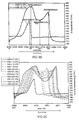
- FIG. 6 the relative course of the normalized impedance Zn for two AMI values is shown in FIG near the optimum AM grade for stable long-term operation.
- an outline of the impedance curve is drawn in four areas I to IV, the different mixing states depending on the impedance curve of the metal halide plasma in the discharge arc.
- the preferred range of adjustment results according to the invention in area III (hatched and highlighted bar). It lies between the frequencies FM2 and FMmin at an impedance between the minimum and the secondary maximum. Here is just below the AM frequency of the minimum, FMmin, one significantly better plasma mixture achieved than in the area II. Only here arises a further increase in color rendering and luminous efficiency as well as a good match between the lighting values in vertical and horizontal Burning position.
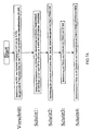
- FIG. 7 shows the sequence of the operating method schematically.
- all 5 are summarized in principle steps. After starting the lamp and waiting for a Waiting time (typically one minute) is initially a preparation step.
- a Waiting time typically one minute
- the preparation step is performed at a very low AM level of 5 to 15% (typically 10%) first a first resonance of the impedance value Z, so ZEXT1 theoretically or experimentally determined by having a large frequency interval is driven off, which certainly includes the extremum.
- the associated frequency point FM1 is used to define a measurement interval MI, the a width of 8 to 25 kHz with the limit points ST (upper limit frequency) and SM (lower limit frequency) and in which FM1 is arranged so that FM1 is about at 55 to 80, preferably 60 to 70% of the distance between SM and ST, where FM1 must always be closer to ST.
- the measurement interval is always traversed from top to bottom, ie from ST to SP.
- AMI 5 to 45%
- 10 to 40% in each case traversing the measuring interval MI becomes.
- the maximum range AMI is to be at its lower end an AM degree in which practically only a single extremum (usually maximum) of Lamp impedance is detectable and at its upper end comprise an AM degree, at least a second maximum has clearly emerged.
- Definition of AMopt happens by Determination of the maximum of the change of the lamp impedance.
- Step 3 is the search for the frequency FMmin (AMopt) associated with AMopt. She can be determined from the characteristic field and at the lamp from the starting point Start from ST.
- step 4 is the final determination of the operating frequency FMopt by the frequency interval OPT between FMmin and a value that is 20% of FM2 is located in the interval between FMmin and FM2, is overrun and the corresponding operating data are analyzed.
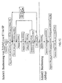
- FIGS. 7b to 7e The five steps are shown in detail in FIGS. 7b to 7e. Then that can ECG carry out continuous operation with AMopt and FMopt.
- a shutdown mechanism be provided, for example, an end-of-life circuit or a query that constantly monitors the standard operating state. Possibly. can in the case of deviation, for example, steps 3 and 4 during continuous operation again be carried out for readjustment.
- Individual steps can also be targeted for the adjustable setting of lamp parameters how to use the color temperature.
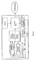
- FIG. 8 shows a block diagram of an associated ECG. It has the following essential components on:
- Timer / Sequencer Here is the time schedule control to control the time duration the warm-up phase and insertion of the embossing phase after ignition and sheet transfer the high-pressure lamp.
- the sweep rate is controlled here for lamp arc stabilization.
- Power stage Full or half bridge with current-limiting Elements and typical frequency response. It is via a supply rail (450 V DC) coupled to the power supply.
- supply rail 450 V DC
- Feedback loop Operation detection of the lamp may be possible. Feedback of lamp parameters such as lamp current and lamp voltage to Setting the control parameters and determining the warm-up or embossing phase, or repetition of embossing phases with other tuning parameters.
Landscapes
- Circuit Arrangements For Discharge Lamps (AREA)
Applications Claiming Priority (2)
| Application Number | Priority Date | Filing Date | Title |
|---|---|---|---|
| DE102004004829 | 2004-01-30 | ||
| DE102004004829A DE102004004829A1 (de) | 2004-01-30 | 2004-01-30 | Betriebsverfahren, elektronisches Vorschaltgerät und System für den Resonanzbetrieb von Hochdrucklampen im longitudinalen Mode |
Publications (3)
| Publication Number | Publication Date |
|---|---|
| EP1560473A2 true EP1560473A2 (fr) | 2005-08-03 |
| EP1560473A3 EP1560473A3 (fr) | 2009-07-15 |
| EP1560473B1 EP1560473B1 (fr) | 2011-02-16 |
Family
ID=34638814
Family Applications (1)
| Application Number | Title | Priority Date | Filing Date |
|---|---|---|---|
| EP04030344A Expired - Lifetime EP1560473B1 (fr) | 2004-01-30 | 2004-12-21 | Méthode et dispositif pour alimenter des lampes à haute pression en mode de résonance longitudinal |
Country Status (7)
| Country | Link |
|---|---|
| US (1) | US7157867B2 (fr) |
| EP (1) | EP1560473B1 (fr) |
| JP (1) | JP4541914B2 (fr) |
| CN (1) | CN100584139C (fr) |
| AT (1) | ATE498988T1 (fr) |
| CA (1) | CA2493842A1 (fr) |
| DE (2) | DE102004004829A1 (fr) |
Families Citing this family (8)
| Publication number | Priority date | Publication date | Assignee | Title |
|---|---|---|---|---|
| EP1805784B1 (fr) * | 2004-10-20 | 2017-03-08 | Philips Intellectual Property & Standards GmbH | Lampe a decharge de gaz a haute pression |
| CN101167159B (zh) * | 2005-04-29 | 2010-12-08 | 皇家飞利浦电子股份有限公司 | 金属卤化物灯 |
| US7911152B2 (en) * | 2006-11-15 | 2011-03-22 | Metrolight Ltd. | High frequency electronic ballast for high intensity discharge lamps and improved drive method therefor |
| US20100194287A1 (en) * | 2007-02-01 | 2010-08-05 | Roberto Vivero-Flores | Electronic ballast for a high intensity discharge lamp |
| DE102009029867A1 (de) | 2009-06-22 | 2010-12-23 | Osram Gesellschaft mit beschränkter Haftung | Hochdruckentladungslampe |
| DE102009048562B4 (de) * | 2009-10-07 | 2012-08-30 | Heraeus Noblelight Gmbh | Verfahren und Vorrichtung zum Betreiben einer elektrodenlosen Entladungslampe mit einem Wobbelgenerator |
| US8358083B2 (en) * | 2009-12-18 | 2013-01-22 | Osram Sylvania Inc. | System and method including self oscillating feedback for acoustic operation of a discharge lamp |
| DE112012000355T5 (de) * | 2011-02-22 | 2013-10-17 | Osram Gmbh | Keramisches Entladungsgefäß und entsprechende Lampe und Verfahren zur Herstellung eines solchen Gefäßes |
Family Cites Families (7)
| Publication number | Priority date | Publication date | Assignee | Title |
|---|---|---|---|---|
| US5684367A (en) * | 1996-01-16 | 1997-11-04 | Osram Sylvania Inc. | Color control and arc stabilization for high-intensity, discharge lamps |
| US6184633B1 (en) * | 1999-06-17 | 2001-02-06 | Philips Electronics North America Corporation | Reduction of vertical segregation in a discharge lamp |
| US6400100B1 (en) * | 2000-07-20 | 2002-06-04 | Philips Electronics North America Corporation | System and method for determining the frequency of longitudinal mode required for color mixing in a discharge lamp |
| US6653799B2 (en) * | 2000-10-06 | 2003-11-25 | Koninklijke Philips Electronics N.V. | System and method for employing pulse width modulation with a bridge frequency sweep to implement color mixing lamp drive scheme |
| US6437517B1 (en) * | 2001-02-22 | 2002-08-20 | Koninklijke Philips Electronics N.V. | Method and system for exciting an azimuthal acoustic and longitudinal acoustic combination mode |
| US6788007B2 (en) * | 2001-12-21 | 2004-09-07 | Koninklijke Philips Electronics N.V. | Use of arc straightening in HID lamps operated at VHF frequencies |
| DE10253904A1 (de) * | 2002-11-19 | 2004-06-03 | Patent-Treuhand-Gesellschaft für elektrische Glühlampen mbH | Betriebsverfahren und System für den Resonanzbetrieb von Hochdrucklampen im longitudinalen Mode |
-
2004
- 2004-01-30 DE DE102004004829A patent/DE102004004829A1/de not_active Withdrawn
- 2004-12-21 AT AT04030344T patent/ATE498988T1/de active
- 2004-12-21 DE DE502004012195T patent/DE502004012195D1/de not_active Expired - Lifetime
- 2004-12-21 EP EP04030344A patent/EP1560473B1/fr not_active Expired - Lifetime
-
2005
- 2005-01-21 CA CA002493842A patent/CA2493842A1/fr not_active Abandoned
- 2005-01-25 US US11/041,313 patent/US7157867B2/en not_active Expired - Fee Related
- 2005-01-31 JP JP2005024423A patent/JP4541914B2/ja not_active Expired - Fee Related
- 2005-01-31 CN CN200510006169A patent/CN100584139C/zh not_active Expired - Fee Related
Also Published As
| Publication number | Publication date |
|---|---|
| CA2493842A1 (fr) | 2005-07-30 |
| DE102004004829A1 (de) | 2005-08-18 |
| JP2005216866A (ja) | 2005-08-11 |
| ATE498988T1 (de) | 2011-03-15 |
| EP1560473B1 (fr) | 2011-02-16 |
| CN1655658A (zh) | 2005-08-17 |
| US20050168176A1 (en) | 2005-08-04 |
| EP1560473A3 (fr) | 2009-07-15 |
| JP4541914B2 (ja) | 2010-09-08 |
| US7157867B2 (en) | 2007-01-02 |
| CN100584139C (zh) | 2010-01-20 |
| DE502004012195D1 (de) | 2011-03-31 |
Similar Documents
| Publication | Publication Date | Title |
|---|---|---|
| EP1729324B1 (fr) | Lampe à haute-pression, ainsi que appareil et méthode pour la commande sur le mode de résonance longitudinal de la lampe à haute-pression. | |
| DE60216402T2 (de) | Betrieb einer Hochdruckgasentladungslampe mit niedrigerer Frequenz | |
| EP1152645B1 (fr) | Méthode et dispositif de control d'un circuit de lampe à décharge | |
| DE69820022T2 (de) | Steuerung für eine hochdruckgasentladungslampe | |
| DE3779931T2 (de) | Frequenzmoduliertes vorschaltgeraet. | |
| DE69936708T2 (de) | Verfahren und vorrichtung zur lampensteuerung | |
| DE69807862T2 (de) | Schaltungsanordnung zum betrieb einer gasentladungslampe | |
| DE69717924T2 (de) | Gerät und Verfahren zum Betreiben einer Entladungslampe | |
| DE69822619T2 (de) | Schaltung zur detektion von bogeninstabilitäten in entladungslampen starker intensität | |
| DE69132178T2 (de) | Vorrichtung für Edelgas-Fluoreszenzentladungslampen | |
| DE69711278T2 (de) | Beleuchtungsanordnung mit entladungslampe | |
| EP1422980B1 (fr) | Procédé de fonctionnement et système pour le fonctionnement en mode de resonance de lampes à haute pression dans mode longitudinal | |
| EP1560473B1 (fr) | Méthode et dispositif pour alimenter des lampes à haute pression en mode de résonance longitudinal | |
| EP0607599A1 (fr) | Procédé et circuit pour alimenter de façon stable une lampe à sodium haute-pression | |
| EP0461441B1 (fr) | Procédé et circuit pour régler l'intensité lumineuse (atténuer) de lampes à décharge | |
| DE60125567T2 (de) | System und verfahren zum pulsbreitenmodulation einstellen für die reduktion von vertikalfarbtrennung in entladungslampen | |
| WO2000019485A1 (fr) | Lampes a decharge avec variation d'intensite destinees a des decharges a inhibition dielectrique | |
| EP1560472B1 (fr) | Méthode pour alimenter des lampes haute-pression sur le mode résonant longitudinal, ballast électronique et système associés | |
| DE60122173T2 (de) | Schaltung | |
| EP1118099B1 (fr) | Lampe a decharge a intensite reglable pour decharges dielectriquement inhibees | |
| EP2195825B1 (fr) | Lampe à décharge haute pression, ainsi que procédé et système associés de fonctionnement de la lampe par résonance en mode longitudinal | |
| EP1653785B1 (fr) | Dispositif d'allumage pour une lampe a decharge haute pression et une lampe a décharge haute pression avec un dispositif d'allumage et méthode d'opération. | |
| DE102016105490B4 (de) | Vorrichtung und Verfahren zum Betreiben einer Entladungslampe, insbesondere für Projektionszwecke | |
| EP1768469B1 (fr) | Méthode pour alimenter une lampe à décharge à haute pression | |
| EP2090142B1 (fr) | Circuit et procédé pour faire fonctionner une lampe à décharge haute pression |
Legal Events
| Date | Code | Title | Description |
|---|---|---|---|
| PUAI | Public reference made under article 153(3) epc to a published international application that has entered the european phase |
Free format text: ORIGINAL CODE: 0009012 |
|
| AK | Designated contracting states |
Kind code of ref document: A2 Designated state(s): AT BE BG CH CY CZ DE DK EE ES FI FR GB GR HU IE IS IT LI LT LU MC NL PL PT RO SE SI SK TR |
|
| AX | Request for extension of the european patent |
Extension state: AL BA HR LV MK YU |
|
| PUAL | Search report despatched |
Free format text: ORIGINAL CODE: 0009013 |
|
| AK | Designated contracting states |
Kind code of ref document: A3 Designated state(s): AT BE BG CH CY CZ DE DK EE ES FI FR GB GR HU IE IS IT LI LT LU MC NL PL PT RO SE SI SK TR |
|
| AX | Request for extension of the european patent |
Extension state: AL BA HR LV MK YU |
|
| 17P | Request for examination filed |
Effective date: 20091120 |
|
| 17Q | First examination report despatched |
Effective date: 20100119 |
|
| AKX | Designation fees paid |
Designated state(s): AT BE BG CH CY CZ DE DK EE ES FI FR GB GR HU IE IS IT LI LT LU MC NL PL PT RO SE SI SK TR |
|
| GRAP | Despatch of communication of intention to grant a patent |
Free format text: ORIGINAL CODE: EPIDOSNIGR1 |
|
| RAP1 | Party data changed (applicant data changed or rights of an application transferred) |
Owner name: OSRAM GESELLSCHAFT MIT BESCHRAENKTER HAFTUNG |
|
| GRAS | Grant fee paid |
Free format text: ORIGINAL CODE: EPIDOSNIGR3 |
|
| GRAA | (expected) grant |
Free format text: ORIGINAL CODE: 0009210 |
|
| AK | Designated contracting states |
Kind code of ref document: B1 Designated state(s): AT BE BG CH CY CZ DE DK EE ES FI FR GB GR HU IE IS IT LI LT LU MC NL PL PT RO SE SI SK TR |
|
| REG | Reference to a national code |
Ref country code: GB Ref legal event code: FG4D Free format text: NOT ENGLISH |
|
| REG | Reference to a national code |
Ref country code: CH Ref legal event code: EP |
|
| REG | Reference to a national code |
Ref country code: IE Ref legal event code: FG4D Free format text: LANGUAGE OF EP DOCUMENT: GERMAN |
|
| REF | Corresponds to: |
Ref document number: 502004012195 Country of ref document: DE Date of ref document: 20110331 Kind code of ref document: P |
|
| REG | Reference to a national code |
Ref country code: DE Ref legal event code: R096 Ref document number: 502004012195 Country of ref document: DE Effective date: 20110331 |
|
| REG | Reference to a national code |
Ref country code: NL Ref legal event code: VDEP Effective date: 20110216 |
|
| LTIE | Lt: invalidation of european patent or patent extension |
Effective date: 20110216 |
|
| PG25 | Lapsed in a contracting state [announced via postgrant information from national office to epo] |
Ref country code: LT Free format text: LAPSE BECAUSE OF FAILURE TO SUBMIT A TRANSLATION OF THE DESCRIPTION OR TO PAY THE FEE WITHIN THE PRESCRIBED TIME-LIMIT Effective date: 20110216 Ref country code: GR Free format text: LAPSE BECAUSE OF FAILURE TO SUBMIT A TRANSLATION OF THE DESCRIPTION OR TO PAY THE FEE WITHIN THE PRESCRIBED TIME-LIMIT Effective date: 20110517 Ref country code: PT Free format text: LAPSE BECAUSE OF FAILURE TO SUBMIT A TRANSLATION OF THE DESCRIPTION OR TO PAY THE FEE WITHIN THE PRESCRIBED TIME-LIMIT Effective date: 20110616 Ref country code: SE Free format text: LAPSE BECAUSE OF FAILURE TO SUBMIT A TRANSLATION OF THE DESCRIPTION OR TO PAY THE FEE WITHIN THE PRESCRIBED TIME-LIMIT Effective date: 20110216 Ref country code: ES Free format text: LAPSE BECAUSE OF FAILURE TO SUBMIT A TRANSLATION OF THE DESCRIPTION OR TO PAY THE FEE WITHIN THE PRESCRIBED TIME-LIMIT Effective date: 20110527 |
|
| PG25 | Lapsed in a contracting state [announced via postgrant information from national office to epo] |
Ref country code: NL Free format text: LAPSE BECAUSE OF FAILURE TO SUBMIT A TRANSLATION OF THE DESCRIPTION OR TO PAY THE FEE WITHIN THE PRESCRIBED TIME-LIMIT Effective date: 20110216 Ref country code: PL Free format text: LAPSE BECAUSE OF FAILURE TO SUBMIT A TRANSLATION OF THE DESCRIPTION OR TO PAY THE FEE WITHIN THE PRESCRIBED TIME-LIMIT Effective date: 20110216 Ref country code: FI Free format text: LAPSE BECAUSE OF FAILURE TO SUBMIT A TRANSLATION OF THE DESCRIPTION OR TO PAY THE FEE WITHIN THE PRESCRIBED TIME-LIMIT Effective date: 20110216 Ref country code: BG Free format text: LAPSE BECAUSE OF FAILURE TO SUBMIT A TRANSLATION OF THE DESCRIPTION OR TO PAY THE FEE WITHIN THE PRESCRIBED TIME-LIMIT Effective date: 20110516 Ref country code: CY Free format text: LAPSE BECAUSE OF FAILURE TO SUBMIT A TRANSLATION OF THE DESCRIPTION OR TO PAY THE FEE WITHIN THE PRESCRIBED TIME-LIMIT Effective date: 20110216 Ref country code: SI Free format text: LAPSE BECAUSE OF FAILURE TO SUBMIT A TRANSLATION OF THE DESCRIPTION OR TO PAY THE FEE WITHIN THE PRESCRIBED TIME-LIMIT Effective date: 20110216 |
|
| REG | Reference to a national code |
Ref country code: IE Ref legal event code: FD4D |
|
| PG25 | Lapsed in a contracting state [announced via postgrant information from national office to epo] |
Ref country code: IE Free format text: LAPSE BECAUSE OF FAILURE TO SUBMIT A TRANSLATION OF THE DESCRIPTION OR TO PAY THE FEE WITHIN THE PRESCRIBED TIME-LIMIT Effective date: 20110216 Ref country code: DK Free format text: LAPSE BECAUSE OF FAILURE TO SUBMIT A TRANSLATION OF THE DESCRIPTION OR TO PAY THE FEE WITHIN THE PRESCRIBED TIME-LIMIT Effective date: 20110216 Ref country code: EE Free format text: LAPSE BECAUSE OF FAILURE TO SUBMIT A TRANSLATION OF THE DESCRIPTION OR TO PAY THE FEE WITHIN THE PRESCRIBED TIME-LIMIT Effective date: 20110216 |
|
| PG25 | Lapsed in a contracting state [announced via postgrant information from national office to epo] |
Ref country code: SK Free format text: LAPSE BECAUSE OF FAILURE TO SUBMIT A TRANSLATION OF THE DESCRIPTION OR TO PAY THE FEE WITHIN THE PRESCRIBED TIME-LIMIT Effective date: 20110216 Ref country code: CZ Free format text: LAPSE BECAUSE OF FAILURE TO SUBMIT A TRANSLATION OF THE DESCRIPTION OR TO PAY THE FEE WITHIN THE PRESCRIBED TIME-LIMIT Effective date: 20110216 Ref country code: RO Free format text: LAPSE BECAUSE OF FAILURE TO SUBMIT A TRANSLATION OF THE DESCRIPTION OR TO PAY THE FEE WITHIN THE PRESCRIBED TIME-LIMIT Effective date: 20110216 |
|
| PLBE | No opposition filed within time limit |
Free format text: ORIGINAL CODE: 0009261 |
|
| STAA | Information on the status of an ep patent application or granted ep patent |
Free format text: STATUS: NO OPPOSITION FILED WITHIN TIME LIMIT |
|
| 26N | No opposition filed |
Effective date: 20111117 |
|
| REG | Reference to a national code |
Ref country code: DE Ref legal event code: R081 Ref document number: 502004012195 Country of ref document: DE Owner name: OSRAM AG, DE Free format text: FORMER OWNER: OSRAM GESELLSCHAFT MIT BESCHRAENKTER HAFTUNG, 81543 MUENCHEN, DE Effective date: 20111213 |
|
| REG | Reference to a national code |
Ref country code: DE Ref legal event code: R097 Ref document number: 502004012195 Country of ref document: DE Effective date: 20111117 |
|
| PG25 | Lapsed in a contracting state [announced via postgrant information from national office to epo] |
Ref country code: IT Free format text: LAPSE BECAUSE OF FAILURE TO SUBMIT A TRANSLATION OF THE DESCRIPTION OR TO PAY THE FEE WITHIN THE PRESCRIBED TIME-LIMIT Effective date: 20110216 |
|
| BERE | Be: lapsed |
Owner name: OSRAM G.M.B.H. Effective date: 20111231 |
|
| PG25 | Lapsed in a contracting state [announced via postgrant information from national office to epo] |
Ref country code: MC Free format text: LAPSE BECAUSE OF NON-PAYMENT OF DUE FEES Effective date: 20111231 |
|
| REG | Reference to a national code |
Ref country code: CH Ref legal event code: PL |
|
| GBPC | Gb: european patent ceased through non-payment of renewal fee |
Effective date: 20111221 |
|
| REG | Reference to a national code |
Ref country code: FR Ref legal event code: ST Effective date: 20120831 |
|
| REG | Reference to a national code |
Ref country code: DE Ref legal event code: R119 Ref document number: 502004012195 Country of ref document: DE Effective date: 20120703 |
|
| PG25 | Lapsed in a contracting state [announced via postgrant information from national office to epo] |
Ref country code: LI Free format text: LAPSE BECAUSE OF NON-PAYMENT OF DUE FEES Effective date: 20111231 Ref country code: GB Free format text: LAPSE BECAUSE OF NON-PAYMENT OF DUE FEES Effective date: 20111221 Ref country code: BE Free format text: LAPSE BECAUSE OF NON-PAYMENT OF DUE FEES Effective date: 20111231 Ref country code: CH Free format text: LAPSE BECAUSE OF NON-PAYMENT OF DUE FEES Effective date: 20111231 Ref country code: DE Free format text: LAPSE BECAUSE OF NON-PAYMENT OF DUE FEES Effective date: 20120703 |
|
| REG | Reference to a national code |
Ref country code: AT Ref legal event code: MM01 Ref document number: 498988 Country of ref document: AT Kind code of ref document: T Effective date: 20111221 |
|
| PG25 | Lapsed in a contracting state [announced via postgrant information from national office to epo] |
Ref country code: FR Free format text: LAPSE BECAUSE OF NON-PAYMENT OF DUE FEES Effective date: 20120102 |
|
| PG25 | Lapsed in a contracting state [announced via postgrant information from national office to epo] |
Ref country code: LU Free format text: LAPSE BECAUSE OF NON-PAYMENT OF DUE FEES Effective date: 20111221 |
|
| PG25 | Lapsed in a contracting state [announced via postgrant information from national office to epo] |
Ref country code: AT Free format text: LAPSE BECAUSE OF NON-PAYMENT OF DUE FEES Effective date: 20111221 |
|
| PG25 | Lapsed in a contracting state [announced via postgrant information from national office to epo] |
Ref country code: IS Free format text: LAPSE BECAUSE OF FAILURE TO SUBMIT A TRANSLATION OF THE DESCRIPTION OR TO PAY THE FEE WITHIN THE PRESCRIBED TIME-LIMIT Effective date: 20110216 |
|
| PG25 | Lapsed in a contracting state [announced via postgrant information from national office to epo] |
Ref country code: TR Free format text: LAPSE BECAUSE OF FAILURE TO SUBMIT A TRANSLATION OF THE DESCRIPTION OR TO PAY THE FEE WITHIN THE PRESCRIBED TIME-LIMIT Effective date: 20110216 |
|
| PG25 | Lapsed in a contracting state [announced via postgrant information from national office to epo] |
Ref country code: HU Free format text: LAPSE BECAUSE OF FAILURE TO SUBMIT A TRANSLATION OF THE DESCRIPTION OR TO PAY THE FEE WITHIN THE PRESCRIBED TIME-LIMIT Effective date: 20110216 |