EP1560727B1 - Glissiere de siege a commande electrique comprenant un ensemble support souple pour une vis-mere - Google Patents
Glissiere de siege a commande electrique comprenant un ensemble support souple pour une vis-mere Download PDFInfo
- Publication number
- EP1560727B1 EP1560727B1 EP03783435A EP03783435A EP1560727B1 EP 1560727 B1 EP1560727 B1 EP 1560727B1 EP 03783435 A EP03783435 A EP 03783435A EP 03783435 A EP03783435 A EP 03783435A EP 1560727 B1 EP1560727 B1 EP 1560727B1
- Authority
- EP
- European Patent Office
- Prior art keywords
- track
- nut
- rigid shaft
- shaft
- rigid
- Prior art date
- Legal status (The legal status is an assumption and is not a legal conclusion. Google has not performed a legal analysis and makes no representation as to the accuracy of the status listed.)
- Expired - Lifetime
Links
Images


Classifications
-
- B—PERFORMING OPERATIONS; TRANSPORTING
- B60—VEHICLES IN GENERAL
- B60N—SEATS SPECIALLY ADAPTED FOR VEHICLES; VEHICLE PASSENGER ACCOMMODATION NOT OTHERWISE PROVIDED FOR
- B60N2/00—Seats specially adapted for vehicles; Arrangement or mounting of seats in vehicles
- B60N2/02—Seats specially adapted for vehicles; Arrangement or mounting of seats in vehicles the seat or part thereof being movable, e.g. adjustable
- B60N2/04—Seats specially adapted for vehicles; Arrangement or mounting of seats in vehicles the seat or part thereof being movable, e.g. adjustable the whole seat being movable
- B60N2/06—Seats specially adapted for vehicles; Arrangement or mounting of seats in vehicles the seat or part thereof being movable, e.g. adjustable the whole seat being movable slidable
- B60N2/067—Seats specially adapted for vehicles; Arrangement or mounting of seats in vehicles the seat or part thereof being movable, e.g. adjustable the whole seat being movable slidable by linear actuators, e.g. linear screw mechanisms
-
- B—PERFORMING OPERATIONS; TRANSPORTING
- B60—VEHICLES IN GENERAL
- B60N—SEATS SPECIALLY ADAPTED FOR VEHICLES; VEHICLE PASSENGER ACCOMMODATION NOT OTHERWISE PROVIDED FOR
- B60N2/00—Seats specially adapted for vehicles; Arrangement or mounting of seats in vehicles
- B60N2/02—Seats specially adapted for vehicles; Arrangement or mounting of seats in vehicles the seat or part thereof being movable, e.g. adjustable
- B60N2/0224—Non-manual adjustments, e.g. with electrical operation
- B60N2/02246—Electric motors therefor
-
- B—PERFORMING OPERATIONS; TRANSPORTING
- B60—VEHICLES IN GENERAL
- B60N—SEATS SPECIALLY ADAPTED FOR VEHICLES; VEHICLE PASSENGER ACCOMMODATION NOT OTHERWISE PROVIDED FOR
- B60N2/00—Seats specially adapted for vehicles; Arrangement or mounting of seats in vehicles
- B60N2/02—Seats specially adapted for vehicles; Arrangement or mounting of seats in vehicles the seat or part thereof being movable, e.g. adjustable
- B60N2/04—Seats specially adapted for vehicles; Arrangement or mounting of seats in vehicles the seat or part thereof being movable, e.g. adjustable the whole seat being movable
- B60N2/06—Seats specially adapted for vehicles; Arrangement or mounting of seats in vehicles the seat or part thereof being movable, e.g. adjustable the whole seat being movable slidable
- B60N2/07—Slide construction
- B60N2/0702—Slide construction characterised by its cross-section
- B60N2/0717—Rounded, e.g. circular
Definitions
- the invention relates to a seat track for an automotive vehicle seat, and more particularly, to a flexible support assembly for supporting a lead screw within the scat track.
- Automotive vehicles include seat assemblies for supporting occupants above an interior floor of the vehicle.
- the seat assembly typically includes a generally horizontal seat cushion and a generally upright seat back coupled to the seal cushion for selective adjustment of the seat back relative to the seat cushion between a plurality of reclined positions.
- the seat assembly also typically includes a track assembly coupled between the seat cushion and the floor of the vehicle to allow linear forward and rearward movement of the seat cushion along the floor of the vehicle.
- the trank assembly typically includes a lower track fixedly secured to the floor of the vehicle and an upper track slidably coupled to the lower trank and fixedly secured to a bottom portion of the seat cushion. It is well known in the seating art to provide a powered track assembly having a lead screw mechanism driven by an electric motor for moving the upper trank relative to the lower track.
- conventional powered track assemblies are known to be susceptible to binding, noise or otherwise erratic operation of the lend screw mechanism due to generally lateral or vertical loading or pre-loading of the upper track relative to the lower track. Such loading or pre-loading can be caused by dimentional varations in the floor of the vehicle, shifting of occupant weight on the seat assembly, or other vehicle accelerations of road inputs associated with normal driving conditions.
- Document FR 2 796 013 A1 discloses a vehicle front seat that is fixed to a vehicle floor using two parallel longitudinal runners.
- the runners comprise a fixed section fixed to the vehicle and a movable section supporting a seat part which slides along the fixed section.
- An adjustment mechanism has an endless screw mounted in a nut housed in a support. Between the nut and the support are interposed transverse plugs, crushing of which is limited by lower and upper lugs which fit without play in housings in the support bottom and in a screw retaining element.
- Document US 5 456 439 B1 discloses a power seat adjuster including a rotatable drive shaft with first and second axial ends and an intermediate arcuate portion connecting the first and second axial ends.
- the first and second axial ends are respectively axially connected to a drive motor gear assembly and to a driven lead screw.
- a horizontal drive block threadingly engaging the lead screw is rotatably and vertically translatingly mounted in an aperture in a lower track for self-alignment of the drive block with respect to the lead screw.
- a housing rotatably receives the axial connection between one end of the drive shaft and the lead screw.
- the drive nut is rotatably and translatingly mounted in a bracket fixed to an upper track for self-alignment of the drive shaft with the lead screw.
- a drive block engages the lead screw and is mounted for rotation and translation in a link.
- the upper and lower tracks have a guide section and an abutment section which collapse together in a self-cinching action under force loading to resist separation of the
- a powered seat track assembly having a lead screw mechanism or drive assembly that provides smooth and quiet adjustment of the upper track relative to the lower track under lateral or vertical loading or pre-loading conditions associated with normal driving conditions.
- a track assembly for selective forward and rearward adjustment of a seat assembly along a floor of an automotive vehicle.
- the track assembly includes a lower track fixedly secured to the floor of the vehicle and an upper track slidably coupled with the lower track and fixedly secured to the seat assembly.
- a shaft is rotatably supported by the upper track and has a helical thread formed thereon.
- a nut is threadingly engaged with the helical thread of the shaft.
- a cage is fixedly secured to the lower track and has a compartment for supporting the nut therein to allow relative rotational movement of the shaft relative to the nut to cause in response sliding displacement of the upper track relative to the lower track.
- the compartment allows a predetermined amount of movement of the nut within the compartment to prevent binding between the rigid shaft and the nut due to loading of the upper track relative to the lower track.
- Figure 1 is a side view of a seat assembly incorporating a powered seat track assembly according to one embodiment of the invention
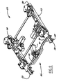
- Figure 2 is a perspective view of the powered seat track assembly
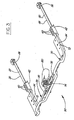
- Figure 3 is a perspective view of a drive assembly of the powered seat track assembly
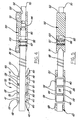
- Figure 4 is a side cross sectional view of the drive assembly
- Figure 5 is a top view of the drive assembly
- Figure 6 is a perspective view of an insulator within the drive assembly
- Figure 7 is a side view of the drive assembly
- Figure 8 is a cross sectional view of a nut in the drive assembly.
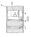
- Figure 9 is a partial view of a guide in the drive assembly.
- a seat assembly is generally indicated as 10 in Figure 1 for supporting an occupant above a floor in an automotive vehicle.
- the seat assembly 10 includes a seat cushion 12.
- a track assembly 20 extends between the seat cushion 12 and the floor of the vehicle for allowing selective forward and rearward adjustment of the seat cushion 12 within the vehicle.
- the track assembly 20 includes a lower track 22 fixedly secured to the floor of the vehicle by bolts 23.
- An upper track 24 is fixedly secured to the bottom of the seat cushion 12 and slidably coupled to the lower track 22 for forward or rearward sliding adjustment of the seat cushion 12 relative to the floor of the vehicle.
- a drive assembly 30 is coupled between the lower 22 and upper 24 tracks for forwardly or rearwardly driving the upper track 24 relative to the lower track 22 in response to a rotary input.
- the drive assembly 30 includes a rigid shaft 32 having first 34 and second 36 ends rotatably supported by the upper track 24 for rotation of the rigid shaft 32 about a longitudinal axis of the rigid shaft 32.
- the rigid shaft 32 includes a generally continuous helical thread 38 formed between the first 34 and second 36 ends of the rigid shaft 32.
- the drive assembly 30 includes at least one nut 40.
- Each nut 40 includes a helically threaded bore 41 for engaging the helical thread 38 of the rigid shaft 32 during rotation of the rigid shaft 32 relative to each nut 40.
- the engagement of the helical threads 38 and the threaded bore 41 converts rotational torque applied to the rigid shaft 32 into an axial thrust load applied to the rigid shaft 32.
- Each nut 40 is secured to the lower track 22 by a cage 42.
- the cage 42 prevents rotation of each nut 40 about the longitudinal axis of the rigid shaft 32 and axially secures each nut 40 to the lower track so that the axial thrust load resulting from rotation of the rigid shaft 32 relative to each nut 40 causes axial displacement of the rigid shaft 32 and the upper track 24 relative to the lower track 22.
- the direction of rotation of the rigid shaft 32 determines the forward or rearward axial thrust load upon the rigid shaft 32 and, hence, the forward or rearward displacement of the upper track 24 relative to the lower track 22.
- a plurality of nuts 40 is included to increase the load carrying capacity of the drive assembly 30.
- a cage 42 extends between top 44 and bottom 46 surfaces and first and second ends 48, 50.
- Bolts (not shown) extend through the lower track 22 and the bottom surface 46 of the cage 42 to fixedly secure the cage 42 to the lower track 22.
- An opening 52 is formed in the top surface 44 defining a receptacle 54 within the cage 42.
- a plurality of walls 56 divide the receptacle 54 into compartments 58. Each compartment 58 nestingly supports one nut 40 therein.
- a bore 60 extends through the first and second ends 48, 50 and the walls 56 of the cage 42 to allow the rigid shaft 32 to pass therethrough.
- An elastic insulator 62 shown in Figure 6, is adapted to be sandwiched between the cage 42 and the nuts 40 to minimize vibration and noise.
- the elastic insulator 62 is molded from an elastomeric material.
- the nuts 40 are supported within the respective compartments 58 such that the threaded bores 41 are generally aligned with the bore 60 in the cage 42.
- the rigid shaft 32 extends through the bore 60 of the cage 42 and remains continuously threadingly engaged with the threaded bores 41 of the nuts 40.
- the nuts 40 remain movable within the compartment 58 to accommodate movement due to spacing between the lower 22 and upper 24 tracks and to help prevent binding between the rigid shaft 32 and the nuts 40 due to such movement.
- each nut 40 includes opposite lateral sides 64 having a gimbaled or raised bump 66 to allow angular movement of the nut 40 relative to the cage 42 and the rigid shaft 32 about an axis (not shown) generally normal to the longitudinal axis of the rigid shaft 32 to accommodate movement due to spacing between the lower 22 and upper 24 tracks and to help prevent binding between the rigid shaft 32 and the nuts 40 due to such movement.
- the drive assembly 30 also includes a flexible shaft 70 extending between a first end 72 coupled to the first end 34 of the rigid shaft 32 and a second end 76 coupled to a transmission 74 for translating the rotary input into rotational movement of the flexible shaft 70.
- the first ends 34, 72 of the rigid shaft 32 and flexible shaft 70 are in splined engagement or keyed in a rotary sense such the rigid shaft 32 rotates with the flexible shaft 70.
- the rotary input is provided by an electric motor 80, as known by those of ordinary skill in the art.
- a hand wheel may be coupled to the transmission 74 to allow manual rotary input by the occupant of the seat assembly 10.
- the first ends 34, 72 of the rigid shaft 32 and flexible shaft 70 are axially held together by a housing or guide 90 fixedly secured to the upper track 24.
- the guide 90 includes a guide bore 92 extending between first 91 and second 93 guide ends for receiving the first ends 34, 72 of the rigid 32 and flexible 70 shafts, respectively, therethrough.
- a bead 95, 96 is fixedly secured to each first end 72 of the rigid 32 and flexible shafts 70 to help guide the first ends 34, 72 through the guide bore 92 and into splined engagement.
- the beads 95, 96 also help to keep the first ends 34, 72 aligned during rotation of the rigid 32 and flexible 70 shafts.
- the guide 90 also includes an abutment wall 97 formed within a portion of the guide bore 92 between the first 91 and second 93 guide ends.
- the first end 34 of the rigid shaft 32 extends through the guide bore 92 in the first guide end 91 and protrudes beyond the abutment wall 97 into a middle portion of the guide bore 92. While in the middle portion of the guide bore 92, the first end 34 of the rigid shaft 32 is presented for splined engagement with the first end 72 of the flexible shaft.
- a retaining pin 98 extends through the rigid shaft 32 between the abutment wall 97 and the first end 34 of the rigid shaft 32 to retain the first end 34 of the rigid shaft 32 within the guide bore 92.
- a spring washer 100 is mounted on the rigid shaft 32 between the abutment wall 97 and the retaining pin 98 for providing an axial pre-load between the threaded bores 41 of the nuts 40 and the helical thread 38 of the rigid shaft 32.
- the occupant of the seat assembly 10 operates a switch (not shown), as commonly known by those skilled in the art, to energize the electric motor 80.
- the electric motor 80 provides the rotary input to the transmission 74 to cause rotational movement of the flexible shaft 70.
- the helical thread 38 of the rigid shaft 32 threadingly engages the threaded bores 41 of the nuts 40 to cause axial displacement of the rigid shaft 32 relative to the nuts 40 and, in turn, sliding movement of the upper track 24 relative to the lower track 22.
- the direction of the sliding movement of the upper track 24 relative to the lower track 22 depends on the direction of rotation of the rigid shaft 32 relative to the nuts 40.
Landscapes
- Engineering & Computer Science (AREA)
- Aviation & Aerospace Engineering (AREA)
- Transportation (AREA)
- Mechanical Engineering (AREA)
- Seats For Vehicles (AREA)
Claims (13)
- Ensemble formant glissière (20) pour permettre un ajustement sélectif vers l'avant et vers l'arrière d'un ensemble formant siège (10) le long d'un plancher d'un véhicule automobile, l'ensemble formant glissière (20) comprenant :une glissière inférieure (22) adaptée à être fixée sur le plancher du véhicule ;une glissière supérieure (24) adaptée à être fixée sur l'ensemble formant siège (10), la glissière supérieure (24) étant couplée en coulissement avec la glissière inférieure (22) ;une tige rigide (32) ayant un filetage hélicoïdal (38) formé sur elle-même, la tige rigide (32) étant supportée en rotation par la glissière supérieure (24) ;au moins un écrou (40) engagé avec le filetage hélicoïdal (38) de la tige rigide (32), ledit au moins un écrou (40)comportant des bosses en saillie (66) disposées sur des côtés latéraux opposés (64) de lui-même ; etune cage (42) fixée sur la glissière inférieure (22), la cage (42) ayant au moins un compartiment (58) pour supporter à l'intérieur ledit au moins un écrou (40), la cage permettant un mouvement de rotation relatif de la tige rigide (32) par rapport audit au moins un écrou (40) pour déplacer la glissière supérieure (24) par rapport à la glissière inférieure (22), ledit au moins un compartiment (58) étant en interaction avec les bosses en saillie (66) dudit au moins un écrou (40), permettant ainsi un mouvement d'amplitude prédéterminée dudit au moins un écrou (40) à l'intérieur dudit au moins un compartiment (58) pour empêcher un coincement entre la tige rigide (32) et ledit au moins un écrou (40) en raison du chargement de la glissière supérieure (24) par rapport à la glissière inférieure (22), caractérisé par :une tige flexible (70),un boîtier (90) qui connecte axialement la tige rigide (32) à la tige flexible (70),un élément d'entrée rotatif imposant un mouvement de rotation à la tige flexible (70), etune rondelle-ressort (100) montée autour de la tige rigide (32) pour assurer une précharge axiale entre ledit au moins un écrou (40) et le filetage hélicoïdal (38) de la tige rigide (32).
- Ensemble formant glissière (20) selon la revendication 1, dans lequel ledit au moins un écrou (40) comprend une pluralité d'écrous (40).
- Ensemble formant glissière (20) selon la revendication 1, dans lequel la cage (42) inclut un trou (52) formé dans une surface supérieure (44) de la cage (42) et définissant un réceptacle (54) pour recevoir ledit au moins un écrou (40).
- Ensemble formant glissière (20) selon la revendication 3, dans lequel le réceptacle (54) inclut une pluralité de parois (56) espacées les unes des autres et définissant ledit au moins un compartiment (58).
- Ensemble formant glissière (20) selon la revendication 1, incluant en outre un perçage (60) formé dans des parois terminales (48, 50) et dans la pluralité de parois espacées (56) de la cage (42) pour permettre la traversée de la tige rigide (32).
- Ensemble formant glissière (20) selon la revendication 1, dans lequel ladite tige flexible (70) est connectée à une transmission (74) pour transférer un mouvement d'entrée en rotation en un mouvement de rotation de la tige flexible (70).
- Ensemble formant glissière (20) selon la revendication 1, dans lequel le boîtier (90) est fixé à la glissière supérieure (24).
- Ensemble formant glissière (20) selon la revendication 1, dans lequel le boîtier (90) inclut un perçage guide (12) formé entre des extrémités (91, 93) du boîtier (90) pour recevoir les premières extrémités (34, 72) de la tige rigide (32) et de la tige flexible (70).
- Ensemble formant glissière (20) selon la revendication 1, dans lequel la tige rigide et la tige flexible (32, 70) incluent un bourrelet (95, 96) formés sur celles-ci à proximité des premières extrémités (34, 72) pour aligner la tige rigide (32) et la tige flexible (70) afin de maintenir l'engagement pendant la rotation.
- Ensemble formant glissière (20) selon la revendication 1, dans lequel le boîtier (90) inclut une paroi de butée (97) formée à l'intérieur du perçage guide (92) entre les extrémités (91, 93) du boîtier (90).
- Ensemble formant glissière (20) selon la revendication 1, incluant une broche de retenue (98) s'étendant à travers la tige rigide (32) dans une position entre la paroi de butée (92) et la première extrémité (34) de la tige rigide (32) pour maintenir la tige rigide (32) à l'intérieur du perçage guide (92).
- Ensemble formant glissière (20) selon la revendication 1, dans lequel la rondelle-ressort (100) est montée autour de la tige rigide (32) entre la paroi de butée (97) et la tige de retenue (98).
- Ensemble formant glissière (20) selon la revendication 1, incluant en outre un isolateur élastique (62) disposé entre la cage (42) et ledit au moins un écrou (40) pour minimiser les bruits et les vibrations entre ledit au moins un écrou (40) et la cage (42).
Applications Claiming Priority (3)
| Application Number | Priority Date | Filing Date | Title |
|---|---|---|---|
| US42591202P | 2002-11-13 | 2002-11-13 | |
| US425912P | 2002-11-13 | ||
| PCT/US2003/036301 WO2004043731A1 (fr) | 2002-11-13 | 2003-11-13 | Glissiere de siege a commande electrique comprenant un ensemble support souple pour une vis-mere |
Publications (2)
| Publication Number | Publication Date |
|---|---|
| EP1560727A1 EP1560727A1 (fr) | 2005-08-10 |
| EP1560727B1 true EP1560727B1 (fr) | 2008-01-02 |
Family
ID=32313073
Family Applications (1)
| Application Number | Title | Priority Date | Filing Date |
|---|---|---|---|
| EP03783435A Expired - Lifetime EP1560727B1 (fr) | 2002-11-13 | 2003-11-13 | Glissiere de siege a commande electrique comprenant un ensemble support souple pour une vis-mere |
Country Status (6)
| Country | Link |
|---|---|
| US (1) | US7472879B2 (fr) |
| EP (1) | EP1560727B1 (fr) |
| AU (1) | AU2003290851A1 (fr) |
| CA (1) | CA2505528A1 (fr) |
| DE (1) | DE60318476T2 (fr) |
| WO (1) | WO2004043731A1 (fr) |
Families Citing this family (8)
| Publication number | Priority date | Publication date | Assignee | Title |
|---|---|---|---|---|
| JP5465868B2 (ja) * | 2008-11-28 | 2014-04-09 | デルタ工業株式会社 | シートのスライド構造 |
| DE102008061109B4 (de) * | 2008-12-09 | 2019-05-09 | GM Global Technology Operations LLC (n. d. Ges. d. Staates Delaware) | Betätigungshebel für eine Längsverstellvorrichtung eines Kraftfahrzeugsitzes |
| WO2011143173A1 (fr) * | 2010-05-11 | 2011-11-17 | Creative Seating Technologies, LLC | Ensemble glissière de siège de véhicule possédant un mécanisme d'entraînement à une seule courroie crantée |
| US9068685B2 (en) * | 2011-08-26 | 2015-06-30 | Rilco Manufacturing Company, Inc. | Pipe anchor |
| JP6529753B2 (ja) * | 2014-08-30 | 2019-06-12 | 株式会社デルタツーリング | パワーシートスライド装置及び乗物用シート |
| JP2017024622A (ja) * | 2015-07-24 | 2017-02-02 | アイシン精機株式会社 | 車両用シートスライド装置 |
| WO2020123595A1 (fr) * | 2018-12-11 | 2020-06-18 | Magna Seating Inc. | Connexion d'alimentation électrique pour ensemble rail long de courant |
| DE102021107897A1 (de) * | 2021-03-29 | 2022-09-29 | Faurecia Autositze Gmbh | Kraftfahrzeugsitz |
Family Cites Families (21)
| Publication number | Priority date | Publication date | Assignee | Title |
|---|---|---|---|---|
| US3043552A (en) * | 1960-03-03 | 1962-07-10 | Gen Motors Corp | Power transmitting mechanism for vehicle seats |
| US4057114A (en) | 1976-01-07 | 1977-11-08 | Anderson Paul J | Hand-held ice auger |
| JPH0541944Y2 (fr) | 1988-12-26 | 1993-10-22 | ||
| JP2780320B2 (ja) * | 1989-03-31 | 1998-07-30 | アイシン精機株式会社 | 自動車用パワーシートスライド装置 |
| US5222402A (en) * | 1991-09-05 | 1993-06-29 | Rockwell International Corporation | Horizontal seat position adjuster |
| JP3161033B2 (ja) | 1992-05-29 | 2001-04-25 | アイシン精機株式会社 | 車両用シートスライド装置 |
| US5447352A (en) | 1992-06-22 | 1995-09-05 | Aisin Seiki Kabushiki Kaisha | Seat slide mechanism for vehicles |
| US5292164A (en) * | 1992-12-23 | 1994-03-08 | Itt Corporation | Power seat adjuster with horizontal slot drive |
| US5456439A (en) | 1993-12-15 | 1995-10-10 | Itt Corporation | Vehicle power seat adjuster with self-aligning lead screw actuator |
| JP2708723B2 (ja) | 1994-06-20 | 1998-02-04 | デルタ工業株式会社 | 車両用シートのセーフティロック機構 |
| US5707035A (en) | 1994-08-31 | 1998-01-13 | Hoover Universal, Inc. | Vehicle seat adjuster |
| JP3646384B2 (ja) | 1995-12-19 | 2005-05-11 | アイシン精機株式会社 | 動力伝達装置 |
| US5769377A (en) * | 1996-06-06 | 1998-06-23 | Lear Corporation | Self-aligning drive nut for vehicle power seat adjuster |
| US5797293A (en) | 1996-12-19 | 1998-08-25 | Lear Corporation | Plastic drive block for vehicle seat adjuster |
| JP3740802B2 (ja) | 1997-08-18 | 2006-02-01 | アイシン精機株式会社 | シートスライド装置 |
| US6021990A (en) | 1998-07-28 | 2000-02-08 | Meritor Automotive Canada, Inc. | Integrated lead screw drive for seat adjuster |
| US5941494A (en) * | 1998-08-25 | 1999-08-24 | Meritor Automotive Canada Inc. | Inertial lock assembly for a seat track |
| JP4103212B2 (ja) * | 1998-11-26 | 2008-06-18 | アイシン精機株式会社 | 車両用パワーシートスライド装置 |
| FR2796013B1 (fr) * | 1999-07-09 | 2001-10-05 | Faure Bertrand Equipements Sa | Mecanisme de reglage de glissiere de siege de vehicule automobile et siege equipe d'un tel mecanisme |
| US6290199B1 (en) | 1999-08-09 | 2001-09-18 | Dura Global Technologies | Drive mechanism for a seat adjuster |
| FR2832362B1 (fr) * | 2001-11-16 | 2004-07-02 | Faurecia Sieges Automobile | Mecanisme de reglage pour siege de vehicule automobile et siege equipe d'un tel mecanisme |
-
2003
- 2003-11-13 CA CA002505528A patent/CA2505528A1/fr not_active Abandoned
- 2003-11-13 EP EP03783435A patent/EP1560727B1/fr not_active Expired - Lifetime
- 2003-11-13 WO PCT/US2003/036301 patent/WO2004043731A1/fr not_active Ceased
- 2003-11-13 DE DE60318476T patent/DE60318476T2/de not_active Expired - Fee Related
- 2003-11-13 US US10/534,601 patent/US7472879B2/en not_active Expired - Fee Related
- 2003-11-13 AU AU2003290851A patent/AU2003290851A1/en not_active Abandoned
Non-Patent Citations (1)
| Title |
|---|
| None * |
Also Published As
| Publication number | Publication date |
|---|---|
| US20060261236A1 (en) | 2006-11-23 |
| WO2004043731A1 (fr) | 2004-05-27 |
| AU2003290851A1 (en) | 2004-06-03 |
| DE60318476T2 (de) | 2009-01-02 |
| CA2505528A1 (fr) | 2004-05-27 |
| DE60318476D1 (de) | 2008-02-14 |
| US7472879B2 (en) | 2009-01-06 |
| EP1560727A1 (fr) | 2005-08-10 |
Similar Documents
| Publication | Publication Date | Title |
|---|---|---|
| EP2114724B2 (fr) | Transmission pour un système à rail motorisé | |
| CA2647317C (fr) | Dispositif de transmission pour un mecanisme de reglage de siege | |
| US7325851B2 (en) | Power seat slide apparatus for a vehicle | |
| CN101670794B (zh) | 用于车辆的动力座椅设备 | |
| KR101257234B1 (ko) | 자동차용 시트의 슬라이딩 이동 장치 및 이에 사용되는 기어 박스 | |
| CN101987584A (zh) | 用于车辆的座椅滑动设备 | |
| US5267717A (en) | Power seat slide device | |
| US6543852B2 (en) | Headrest device | |
| US12109923B2 (en) | Longitudinal adjuster and vehicle seat | |
| CA2179200A1 (fr) | Dispositif de reglage de siege de vehicule, actionne par moteur, comprenant un systeme d'actionnement par vis de commande a autoalignement | |
| US7472879B2 (en) | Power seat track having a flexible support assembly for a lead screw | |
| US5909866A (en) | Transmission assembly for vehicle seat adjuster with mechanical brake to prevent back driving | |
| KR20090092951A (ko) | 자동차 시트 슬라이딩 장치의 기어박스 | |
| KR20010101362A (ko) | 의자 등받이 조정을 위한 로드 보상 장치 | |
| EP0901425A1 (fr) | Dispositif de reglage de siege de vehicule actionne par moteur a actionnement par vis de commande horizontale et centrale | |
| CN108657031B (zh) | 具有张紧作用元件的斜躺座椅总成 | |
| KR101028729B1 (ko) | 차량용 스티어링컬럼 | |
| JPH086597Y2 (ja) | 車両用のパワーシートスライド装置 | |
| US6179265B1 (en) | Single horizontal drive configuration for a seat adjuster | |
| JP5476453B2 (ja) | 車両用シートのパワースライド装置 | |
| JP2560511Y2 (ja) | 自動車用シート | |
| KR200213846Y1 (ko) | 자동차용 시트볼스터 | |
| FR2744965A1 (fr) | Agencement d'organes dans le compartiment moteur d'un vehicule automobile | |
| JPH0649472Y2 (ja) | シートリフター |
Legal Events
| Date | Code | Title | Description |
|---|---|---|---|
| PUAI | Public reference made under article 153(3) epc to a published international application that has entered the european phase |
Free format text: ORIGINAL CODE: 0009012 |
|
| 17P | Request for examination filed |
Effective date: 20050513 |
|
| AK | Designated contracting states |
Kind code of ref document: A1 Designated state(s): AT BE BG CH CY CZ DE DK EE ES FI FR GB GR HU IE IT LI LU MC NL PT RO SE SI SK TR |
|
| AX | Request for extension of the european patent |
Extension state: AL LT LV MK |
|
| RAP1 | Party data changed (applicant data changed or rights of an application transferred) |
Owner name: INTIER AUTOMOTIVE INC. |
|
| DAX | Request for extension of the european patent (deleted) | ||
| RBV | Designated contracting states (corrected) |
Designated state(s): DE FR GB |
|
| 17Q | First examination report despatched |
Effective date: 20060720 |
|
| GRAP | Despatch of communication of intention to grant a patent |
Free format text: ORIGINAL CODE: EPIDOSNIGR1 |
|
| RBV | Designated contracting states (corrected) |
Designated state(s): DE FR GB |
|
| GRAS | Grant fee paid |
Free format text: ORIGINAL CODE: EPIDOSNIGR3 |
|
| RBV | Designated contracting states (corrected) |
Designated state(s): DE FR GB |
|
| GRAA | (expected) grant |
Free format text: ORIGINAL CODE: 0009210 |
|
| AK | Designated contracting states |
Kind code of ref document: B1 Designated state(s): DE FR GB |
|
| REG | Reference to a national code |
Ref country code: GB Ref legal event code: FG4D |
|
| REF | Corresponds to: |
Ref document number: 60318476 Country of ref document: DE Date of ref document: 20080214 Kind code of ref document: P |
|
| ET | Fr: translation filed | ||
| PLBE | No opposition filed within time limit |
Free format text: ORIGINAL CODE: 0009261 |
|
| STAA | Information on the status of an ep patent application or granted ep patent |
Free format text: STATUS: NO OPPOSITION FILED WITHIN TIME LIMIT |
|
| 26N | No opposition filed |
Effective date: 20081003 |
|
| GBPC | Gb: european patent ceased through non-payment of renewal fee |
Effective date: 20081113 |
|
| REG | Reference to a national code |
Ref country code: FR Ref legal event code: ST Effective date: 20090731 |
|
| PG25 | Lapsed in a contracting state [announced via postgrant information from national office to epo] |
Ref country code: DE Free format text: LAPSE BECAUSE OF NON-PAYMENT OF DUE FEES Effective date: 20090603 |
|
| PG25 | Lapsed in a contracting state [announced via postgrant information from national office to epo] |
Ref country code: GB Free format text: LAPSE BECAUSE OF NON-PAYMENT OF DUE FEES Effective date: 20081113 |
|
| PG25 | Lapsed in a contracting state [announced via postgrant information from national office to epo] |
Ref country code: FR Free format text: LAPSE BECAUSE OF NON-PAYMENT OF DUE FEES Effective date: 20081130 |