EP1561011B1 - Systeme d'actionneur oscillant servant a commander la levee d'une soupape de changement des gaz dans la culasse d'un moteur a combustion - Google Patents
Systeme d'actionneur oscillant servant a commander la levee d'une soupape de changement des gaz dans la culasse d'un moteur a combustion Download PDFInfo
- Publication number
- EP1561011B1 EP1561011B1 EP03750715A EP03750715A EP1561011B1 EP 1561011 B1 EP1561011 B1 EP 1561011B1 EP 03750715 A EP03750715 A EP 03750715A EP 03750715 A EP03750715 A EP 03750715A EP 1561011 B1 EP1561011 B1 EP 1561011B1
- Authority
- EP
- European Patent Office
- Prior art keywords
- stroke region
- stroke
- cam track
- actuating element
- gas change
- Prior art date
- Legal status (The legal status is an assumption and is not a legal conclusion. Google has not performed a legal analysis and makes no representation as to the accuracy of the status listed.)
- Expired - Lifetime
Links
- 238000002485 combustion reaction Methods 0.000 title claims abstract description 21
- 230000001133 acceleration Effects 0.000 claims description 8
- 239000000203 mixture Substances 0.000 abstract description 4
- 238000002360 preparation method Methods 0.000 abstract description 3
- 230000005540 biological transmission Effects 0.000 description 4
- 239000000446 fuel Substances 0.000 description 2
- 238000004519 manufacturing process Methods 0.000 description 2
- 241001433879 Camarea Species 0.000 description 1
- 230000001419 dependent effect Effects 0.000 description 1
- 230000000694 effects Effects 0.000 description 1
- 230000005284 excitation Effects 0.000 description 1
- 238000000034 method Methods 0.000 description 1
- 230000000737 periodic effect Effects 0.000 description 1
- 230000000750 progressive effect Effects 0.000 description 1
Images
Classifications
-
- F—MECHANICAL ENGINEERING; LIGHTING; HEATING; WEAPONS; BLASTING
- F01—MACHINES OR ENGINES IN GENERAL; ENGINE PLANTS IN GENERAL; STEAM ENGINES
- F01L—CYCLICALLY OPERATING VALVES FOR MACHINES OR ENGINES
- F01L1/00—Valve-gear or valve arrangements, e.g. lift-valve gear
- F01L1/02—Valve drive
- F01L1/04—Valve drive by means of cams, camshafts, cam discs, eccentrics or the like
- F01L1/08—Shape of cams
-
- F—MECHANICAL ENGINEERING; LIGHTING; HEATING; WEAPONS; BLASTING
- F01—MACHINES OR ENGINES IN GENERAL; ENGINE PLANTS IN GENERAL; STEAM ENGINES
- F01L—CYCLICALLY OPERATING VALVES FOR MACHINES OR ENGINES
- F01L13/00—Modifications of valve-gear to facilitate reversing, braking, starting, changing compression ratio, or other specific operations
- F01L13/0005—Deactivating valves
-
- F—MECHANICAL ENGINEERING; LIGHTING; HEATING; WEAPONS; BLASTING
- F01—MACHINES OR ENGINES IN GENERAL; ENGINE PLANTS IN GENERAL; STEAM ENGINES
- F01L—CYCLICALLY OPERATING VALVES FOR MACHINES OR ENGINES
- F01L9/00—Valve-gear or valve arrangements actuated non-mechanically
- F01L9/20—Valve-gear or valve arrangements actuated non-mechanically by electric means
-
- F—MECHANICAL ENGINEERING; LIGHTING; HEATING; WEAPONS; BLASTING
- F01—MACHINES OR ENGINES IN GENERAL; ENGINE PLANTS IN GENERAL; STEAM ENGINES
- F01L—CYCLICALLY OPERATING VALVES FOR MACHINES OR ENGINES
- F01L9/00—Valve-gear or valve arrangements actuated non-mechanically
- F01L9/20—Valve-gear or valve arrangements actuated non-mechanically by electric means
- F01L9/22—Valve-gear or valve arrangements actuated non-mechanically by electric means actuated by rotary motors
-
- F—MECHANICAL ENGINEERING; LIGHTING; HEATING; WEAPONS; BLASTING
- F01—MACHINES OR ENGINES IN GENERAL; ENGINE PLANTS IN GENERAL; STEAM ENGINES
- F01L—CYCLICALLY OPERATING VALVES FOR MACHINES OR ENGINES
- F01L2820/00—Details on specific features characterising valve gear arrangements
- F01L2820/01—Absolute values
-
- Y—GENERAL TAGGING OF NEW TECHNOLOGICAL DEVELOPMENTS; GENERAL TAGGING OF CROSS-SECTIONAL TECHNOLOGIES SPANNING OVER SEVERAL SECTIONS OF THE IPC; TECHNICAL SUBJECTS COVERED BY FORMER USPC CROSS-REFERENCE ART COLLECTIONS [XRACs] AND DIGESTS
- Y10—TECHNICAL SUBJECTS COVERED BY FORMER USPC
- Y10T—TECHNICAL SUBJECTS COVERED BY FORMER US CLASSIFICATION
- Y10T74/00—Machine element or mechanism
- Y10T74/21—Elements
- Y10T74/2101—Cams
-
- Y—GENERAL TAGGING OF NEW TECHNOLOGICAL DEVELOPMENTS; GENERAL TAGGING OF CROSS-SECTIONAL TECHNOLOGIES SPANNING OVER SEVERAL SECTIONS OF THE IPC; TECHNICAL SUBJECTS COVERED BY FORMER USPC CROSS-REFERENCE ART COLLECTIONS [XRACs] AND DIGESTS
- Y10—TECHNICAL SUBJECTS COVERED BY FORMER USPC
- Y10T—TECHNICAL SUBJECTS COVERED BY FORMER US CLASSIFICATION
- Y10T74/00—Machine element or mechanism
- Y10T74/21—Elements
- Y10T74/2101—Cams
- Y10T74/2107—Follower
Definitions
- the invention relates to a Schwenkaktor device for stroke control of a gas exchange valve in a cylinder head of an internal combustion engine according to the features in the preamble of claim 1.
- a Schwenkaktor device for stroke control of a gas exchange valve in a cylinder head of an internal combustion engine comprising a pivot motor with a shaft to which an actuator is arranged with a control track is described.
- the actuating element is used to open a gas exchange valve, wherein a second actuating element with a second control path is arranged on the first actuating element.
- a disadvantage of the described Schwenkaktor device is that the gas exchange valve despite the o. G. Design, only with a Ventilhubverlauf is actuated.
- Object of the present invention is to further develop a generic Schwenkaktor device to the effect that for the gas exchange valve different Ventilhubverrise are possible.
- the invention extends the existing Schwenkaktor device by a second actuator in the opposite direction of rotation with a smaller stroke relative to the main cam.
- This second actuator does not fully open the valve and is used only for small strokes in the range of low engine speeds.
- the Schwenkaktor device is energized so that the shaft pivots only in the direction of the second actuating element, while at high speeds is pivoted exclusively in the direction of the first actuating element. Due to the low stroke, the Schwenkaktor device consumes less power at low speeds advantageously.
- the two actuators form a double cam, which is bumpless actuated in two directions.
- the production of such a designed double control track whose Nullhub Schemee are adjacent, simple and inexpensive.
- the current consumption at low speeds is low. Furthermore, valve noise generated by opening the gas exchange valve on the valve seat is reduced by the design according to the invention.
- the second actuator balances the moments of the spring element, an actuator spring, against the moments of the valve spring.
- the resulting torque on the camshaft is nearly zero, depending on tolerances, and thus the camshaft can be kept almost de-energized in any angular position of the second actuator.
- Such a system has a low dynamics, since this is built up solely by the moment structure of the swing motor (by energization).
- Another advantage is the improvement in the gas dynamics when changing the charge to name, as due to the small valve lift supersonic speeds in the valve gap can be generated, which contribute significantly to a good mixture preparation positive.
- system overshoots do not affect, since the valve is not changed in these areas.
- the second control track is configured.
- the Tax track divided into two areas.
- the first stroke range from zero lift or a defined value (eg from 0.6 mm to 1.5 mm lift height)
- the kinematics torque of the spring element is compensated only to a small extent so that a spring-induced acceleration is impressed on the swivel actuator device
- the second stroke range eg from 1.5 mm to approx. 3.5 mm
- the kinematics moment of the spring element is overcompensated, so that a spring-related deceleration is impressed on the pivoting actuator device over this stroke range.
- the two actuating elements either radially on the outer circumference of the shaft, whereby a plurality of gas exchange valves can be operated by a Schwenkaktor device or attach to the frontal surface of the shaft a slide track with which a single gas exchange valve is controlled.
- the Schwenkaktor device according to the invention can be arranged according to claim 13, both the inlet side and the exhaust side in the cylinder head of the internal combustion engine. This common part principle allows cost-effective production.
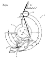
- Fig. 1 shows a schematic representation of a Schwenkaktor device 1 according to the invention in the installed position in a cylinder head 3.
- the Schwenkaktor device 1 consists essentially of a pivot motor 4 with a stator, not shown, and a rotor, not shown.
- the rotor is fixedly connected to a shaft 5 with a common axis of rotation 5a.
- the shaft 5 has radially at its periphery an actuating element 6 with a first control track 7, a half cam on.
- the first control path 7 is divided into three individual regions, a first zero-stroke region 7a, a first stroke region 7b and a full-stroke region 7c.
- a second actuating element 8 with a second control path 9 adjoins the first zero-stroke region 7a in the opposite direction of rotation.
- the second control track 9 is likewise subdivided into three areas, a second zero stroke area 9a, a second stroke area 9b and a partial lift area 9c.
- the second stroke region 9b is in turn divided into an acceleration stroke region 9b ', which adjoins the second zero stroke region 9a, followed by a delay stroke region 9b "The first zero stroke region 7a and the second zero stroke region 9a adjacent thereto have the same constant radius" R1 ".
- the distance between the first control track 7 in the first stroke region 7b increases in accordance with a cam contour via a rotation angle in the direction of the full stroke region 7c
- the full stroke region 7c following the first stroke region 7b in turn has a constant radius "R2" Radius difference between R2 and R1 corresponds to a height "h 1 ", corresponding to a maximum gas exchange valve lift
- the second stroke region 9b adjoining the second zero stroke region 9a also has a cam contour, that is, the distance of the control path 9 from the rotation axis 5a increases in the lifting area 9b via a twist angle in the direction Operahu b range 9c.
- the acceleration stroke region 9b ' has a degressive, the delay stroke region 9b "a progressive radius increase.
- the acceleration stroke range 9b compensates for the kinematics torque of the spring element only to a small extent and thus imposes spring-induced acceleration on the system
- the kinematic moment of the spring element 12 is overcompensated in the deceleration stroke range 9b "and thus the system is impressed with spring-induced deceleration over this stroke range 9b 'and the delay stroke 9b "can occupy different angular sections of the control track 9 depending on the internal combustion engine or omitted entirely in favor of a normal cam contour.
- the power transmission element 10 is based, on the one hand, on a clearance compensation element 14, a hydraulic valve clearance compensation element, which is arranged stationarily in the cylinder head 3 and, on the other hand, on a valve stem end of a gas exchange valve 2 which is held in the closed position by a valve spring 11.
- the swivel motor 4 pivots at high requested load or speed in the direction of the full-stroke range 7c and at a lower requested load or speed in the direction of the partial lift ranges 9c.
- the gas exchange valve 2 is opened in accordance with the control tracks 7 and 9, respectively.
- the pivoting movement of the swivel motor 4 is assisted during opening by the spring element 12 and the energy stored in the spring element 12 is delivered to the valve spring 11 during the opening process.
- the valve spring 11 is the stored energy in her largely to the spring element 12 from.
- Subsequent partial lifting area 9c is a torque-neutral cam area in which electroless holding of gas exchange valve 2 in the open position, at maximum partial lift, especially at low engine speeds and high loads, is made possible.
- the height h 2 of the Operahub Schemees 9c is designed according to internal combustion engine-dependent parameters.
- the acceleration stroke region 9b 'of the second actuating element 8 can be made smaller in magnitude than the region of the deceleration stroke region 9b.
- the load control of the internal combustion engine is simpler and allows more fuel-efficient operating points in the lower load range.
- Another advantage of the Schwenkaktor device 1 according to the invention is the lower power consumption at low speeds at small valve strokes against full valve lifts to mention. Due to the small air gap with a small valve lift of the inlet valve, it is possible to achieve supersonic inlet flow rates which improve the mixture preparation and thus reduce the emissions of the internal combustion engine. A further improvement results from opening the intake valve twice, a first time to draw in the combustion air and a second time to swirl the combustion air with fuel. This leads to a significantly improved mixing of air and fuel and thus to a more uniform combustion.
- the opening speed of the valve movement can be reduced if desired, and thus reduces the Vorlassauspat in the exhaust system become.
- the acoustic excitation of the exhaust system can be reduced and the overall noise level of the internal combustion engine can also be reduced.
Landscapes
- Engineering & Computer Science (AREA)
- Mechanical Engineering (AREA)
- General Engineering & Computer Science (AREA)
- Valve Device For Special Equipments (AREA)
Abstract
Claims (13)
- Dispositif d'actionneur de pivotement (1) servant à commander la levée d'une soupape de renouvellement des gaz (2) dans une culasse (3) d'un moteur à combustion interne, comprenant un moteur de pivotement (4) avec un arbre (5) sur lequel est disposé un élément d'actionnement (6) muni d'une première piste de commande (7) pour ouvrir la soupape de renouvellement des gaz (2), la première piste de commande (7) étant divisée en une première zone de levée à zéro (7a) et une première zone de levée (7b),
caractérisé en ce qu'
un deuxième élément d'actionnement (8) muni d'une deuxième piste de commande (9) pour ouvrir la soupape de renouvellement des gaz (2) est disposé sur le premier élément d'actionnement (6) et la deuxième piste de commande (9) est divisée au moins en une deuxième zone de levée à zéro (9a) et une deuxième zone de levée (9b). - Dispositif selon la revendication 1,
caractérisé en ce que
la deuxième zone de levée à zéro (9a) est disposée sur la première zone de levée à zéro (7a) de la première piste de commande (7). - Dispositif selon la revendication 1 ou 2,
caractérisé en ce que
la première piste de commande (7) présente une zone de levée totale (7c) et/ou la deuxième piste de commande (9) présente une zone de levée partielle (9c). - Dispositif selon la revendication 3,
caractérisé en ce que
la zone de levée totale (7c) est disposée sur la première zone de levée (7b) et la zone de levée partielle (9c) est disposée sur la deuxième zone de levée (9b). - Dispositif selon l'une des revendications précédentes,
caractérisé en ce qu'
une hauteur de levée (h2) de la zone de levée partielle (9c) est inférieure à une hauteur de levée (h1) de la zone de levée totale (7c). - Dispositif selon l'une des revendications précédentes,
caractérisé en ce que
la hauteur de levée (h1) de la zone de levée totale (7c) est la zone de levée maximale de la soupape de renouvellement des gaz (2). - Dispositif selon l'une des revendications précédentes,
caractérisé en ce que
la deuxième zone de levée (9b) est divisée, à partir de la deuxième zone de levée à zéro (9a), en une zone de levée d'accélération (9b') puis en une zone de levée de ralentissement (9b"). - Dispositif selon la revendication 7, dans lequel
caractérisé en ce qu'
une distance entre la piste de commande (9) dans la zone de levée d'accélération (9b') et la l'axe de rotation (5a) augmente de manière dégressive sur un angle de rotation en direction de la zone de levée partielle (9c). - Dispositif selon la revendication 7,
caractérisé en ce qu'
une distance entre la piste de commande (9) dans la zone de levée de ralentissement (9b") et l'axe de rotation (5a) augmente progressivement sur un angle de rotation en direction de la zone de levée partielle (9c). - Dispositif selon la revendication 5,
caractérisé en ce que
l'élément d'actionnement (6) et le deuxième élément d'actionnement (8) sont disposés radialement ou axialement sur l'arbre (5). - Dispositif selon l'une des revendications précédentes,
caractérisé en ce qu'
un élément de transmission (10) est disposé entre l'élément d'actionnement (6, 8) et la soupape de renouvellement des gaz (2). - Dispositif selon la revendication 11,
caractérisé en ce que
l'élément de transmission (10) est un levier compensateur ou un levier compensateur de roulement ou un culbuteur. - Dispositif selon l'une des revendications précédentes, dans lequel le moteur à combustion interne présente des soupapes de renouvellement des gaz d'admission et des soupapes de renouvellement des gaz d'échappement,
caractérisé en ce que
le dispositif d'actionneur de pivotement (1) peut être disposé sur les soupapes de renouvellement des gaz d'admission et/ou les soupapes de renouvellement des gaz d'échappement.
Applications Claiming Priority (3)
| Application Number | Priority Date | Filing Date | Title |
|---|---|---|---|
| DE10252991 | 2002-11-14 | ||
| DE10252991A DE10252991A1 (de) | 2002-11-14 | 2002-11-14 | Schwenkaktor-Vorrichtung zur Hubsteuerung eines Gaswechselventils im Zylinderkopf einer Brennkraftmaschine |
| PCT/EP2003/011409 WO2004044392A1 (fr) | 2002-11-14 | 2003-10-15 | Systeme d'actionneur oscillant servant a commander la levee d'une soupape de changement des gaz dans la culasse d'un moteur a combustion |
Publications (2)
| Publication Number | Publication Date |
|---|---|
| EP1561011A1 EP1561011A1 (fr) | 2005-08-10 |
| EP1561011B1 true EP1561011B1 (fr) | 2006-12-13 |
Family
ID=32185627
Family Applications (1)
| Application Number | Title | Priority Date | Filing Date |
|---|---|---|---|
| EP03750715A Expired - Lifetime EP1561011B1 (fr) | 2002-11-14 | 2003-10-15 | Systeme d'actionneur oscillant servant a commander la levee d'une soupape de changement des gaz dans la culasse d'un moteur a combustion |
Country Status (4)
| Country | Link |
|---|---|
| US (1) | US7111598B2 (fr) |
| EP (1) | EP1561011B1 (fr) |
| DE (2) | DE10252991A1 (fr) |
| WO (1) | WO2004044392A1 (fr) |
Families Citing this family (19)
| Publication number | Priority date | Publication date | Assignee | Title |
|---|---|---|---|---|
| DE10311275A1 (de) * | 2003-03-14 | 2004-09-30 | Bayerische Motoren Werke Ag | Ventiltrieb für einen Verbrennungsmotor |
| JP4049092B2 (ja) * | 2003-12-12 | 2008-02-20 | トヨタ自動車株式会社 | 動弁装置 |
| DE102004054775B4 (de) * | 2004-11-12 | 2006-09-21 | Bayerische Motoren Werke Ag | Vorrichtung und Verfahren zur Regelung des Hubverlaufes eines Auslass-Gaswechselventils einer Brennkraftmaschine |
| DE102004054740B4 (de) * | 2004-11-12 | 2007-10-25 | Bayerische Motoren Werke Ag | Verfahren zur Erkennung eines Fehlers in einem Wegsignal eines Wegsensors einer Drehaktuatorvorrichtung |
| DE102004054759B4 (de) * | 2004-11-12 | 2006-08-10 | Bayerische Motoren Werke Ag | Verfahren zur Kalibrierung eines Wegsensors einer Drehaktuatorvorrichtung zur Ansteuerung eines Gaswechselventils einer Brennkraftmaschine |
| DE102004054776B3 (de) * | 2004-11-12 | 2006-03-16 | Bayerische Motoren Werke Ag | Verfahren zur Kalibrierung eines Wegsensors einer Drehaktuatorvorrichtung zur Ansteuerung eines Gaswechselventils einer Brennkraftmaschine |
| DE102004054773B4 (de) * | 2004-11-12 | 2006-12-28 | Bayerische Motoren Werke Ag | Vorrichtung zur Regelung des Hubverlaufes eines Gaswechselventils einer Brennkraftmaschine |
| DE102006005944A1 (de) * | 2006-02-09 | 2007-08-23 | Bayerische Motoren Werke Ag | Verbrennungsmotor mit einem elektrischen Ventiltrieb |
| JP4412318B2 (ja) * | 2006-03-20 | 2010-02-10 | トヨタ自動車株式会社 | 弁駆動装置 |
| US7708254B2 (en) | 2007-08-07 | 2010-05-04 | Warren Controls, Inc. | Actuator apparatus for operating and locking a control valve and a method for its use |
| GB0920152D0 (en) * | 2009-11-18 | 2009-12-30 | Camcon Ltd | Rotary electromagnetic actuator |
| ES2390400T3 (es) | 2009-12-16 | 2012-11-12 | Iveco Motorenforschung Ag | Sistema de accionamiento de válvula variable mecánico para funcionamientos de motor de 2 tiempos y de 4 tiempos |
| US8360387B2 (en) * | 2010-03-26 | 2013-01-29 | Bose Corporation | Actuator including mechanism for converting rotary motion to linear motion |
| KR101209736B1 (ko) * | 2010-09-30 | 2012-12-07 | 기아자동차주식회사 | 가변 밸브 리프트 장치 |
| US11353084B2 (en) | 2013-03-15 | 2022-06-07 | Clearmotion Acquisition I Llc | Rotary actuator driven vibration isolation |
| US9291300B2 (en) | 2013-03-15 | 2016-03-22 | Bose Corporation | Rotary actuator driven vibration isolation |
| GB201616956D0 (en) * | 2016-10-06 | 2016-11-23 | Jaguar Land Rover Limited | Method of controlling a valve train |
| GB2563064B (en) * | 2017-06-02 | 2022-05-18 | Camcon Auto Ltd | Valve actuators |
| EP4256181A4 (fr) | 2020-12-03 | 2024-11-20 | Jacobs Vehicle Systems, Inc. | Système d'actionneur rotatif de commande de l'actionnement des soupapes dans un moteur à combustion interne |
Family Cites Families (8)
| Publication number | Priority date | Publication date | Assignee | Title |
|---|---|---|---|---|
| US3261338A (en) * | 1964-07-13 | 1966-07-19 | Automobile Racing Club Of Okla | Valve timing mechanism |
| US4723516A (en) * | 1985-11-25 | 1988-02-09 | Slagley Michael W | Valve open duration and timing controller |
| US4864984A (en) * | 1986-09-02 | 1989-09-12 | Blish Nelson A | Rotary valve internal combustion engine |
| US5253546A (en) * | 1990-05-29 | 1993-10-19 | Clemson University | Variable valve actuating apparatus |
| US5873335A (en) * | 1998-01-09 | 1999-02-23 | Siemens Automotive Corporation | Engine valve actuation control system |
| DE19913742A1 (de) * | 1999-03-26 | 2000-09-28 | Bayerische Motoren Werke Ag | Vorrichtung zur Hubverstellung eines Gaswechselventils im Zylinderkopf einer Brennkraftmaschine |
| DE10120449A1 (de) * | 2001-04-26 | 2002-10-31 | Ina Schaeffler Kg | Elektromotorisch verdrehbare Welle |
| DE10140461A1 (de) * | 2001-08-17 | 2003-02-27 | Bayerische Motoren Werke Ag | Drehaktor-Vorrichtung zur Hubsteuerung eines Gaswechselventils im Zylinderkopf einer Brennkraftmaschine |
-
2002
- 2002-11-14 DE DE10252991A patent/DE10252991A1/de not_active Withdrawn
-
2003
- 2003-10-15 EP EP03750715A patent/EP1561011B1/fr not_active Expired - Lifetime
- 2003-10-15 DE DE50305989T patent/DE50305989D1/de not_active Expired - Lifetime
- 2003-10-15 WO PCT/EP2003/011409 patent/WO2004044392A1/fr not_active Ceased
-
2005
- 2005-05-13 US US11/128,185 patent/US7111598B2/en not_active Expired - Fee Related
Also Published As
| Publication number | Publication date |
|---|---|
| DE10252991A1 (de) | 2004-05-27 |
| US7111598B2 (en) | 2006-09-26 |
| DE50305989D1 (de) | 2007-01-25 |
| US20060016408A1 (en) | 2006-01-26 |
| EP1561011A1 (fr) | 2005-08-10 |
| WO2004044392A1 (fr) | 2004-05-27 |
Similar Documents
| Publication | Publication Date | Title |
|---|---|---|
| EP1561011B1 (fr) | Systeme d'actionneur oscillant servant a commander la levee d'une soupape de changement des gaz dans la culasse d'un moteur a combustion | |
| DE10140635B4 (de) | Vorrichtung zur variablen Ventilhubverstellung von Gaswechselventilen einer Verbrennungskraftmaschine | |
| DE10063997A1 (de) | Variable Ventilbetätigungsvorrichtung für Motoren mit innerer Verbrennung | |
| DE19815112A1 (de) | Anordnung zur variablen Ventilzeitsteuerung und Ventilbetätigung | |
| DE19548389A1 (de) | Verstellvorrichtung für den Hubverlauf eines Gaswechselventils einer Brennkraftmaschine | |
| EP2118454B1 (fr) | dispositif de commande de soupape pour moteur à combustion interne à piston | |
| DE102004008350A1 (de) | Motorventilbetätigungssystem | |
| DE10228022A1 (de) | Ventilhubvorrichtung zur Hubverstellung der Gaswechselventile einer Verbrennungskraftmaschine | |
| EP1853797B1 (fr) | Commande mecanique variable de soupapes d'un moteur a combustion interne | |
| DE69303740T2 (de) | Ventilantrieb für eine Brennkraftmaschine | |
| EP0244878B1 (fr) | Commande électromagnétique-hydraulique de soupapes des moteurs à combustion interne | |
| EP1760278A2 (fr) | Système de contrôle de course variable de soupape pour un moteur à combustion | |
| DE4410034B4 (de) | Ventilsteuersystem eines Motors | |
| WO2021115711A1 (fr) | Régulateur de levée pour un engrenage de vanne à levée variable à deux positions de travail | |
| EP1375843B1 (fr) | Moteur à combustion interne | |
| DE102007020129A1 (de) | Raumnockenventiltrieb mit modifizierter Raumnockengeometrie | |
| EP1608852B1 (fr) | Dispositif d'actionnement variable des soupapes d'echange des gaz de moteurs a combustion interne et procede permettant de faire fonctionner un dispositif de ce type | |
| DE102018130428A1 (de) | Hubvariabler Ventiltrieb mit wenigstens zwei Arbeitslagen | |
| DE102020109260A1 (de) | Ventilsteuerung für eine Ventilabschaltung und Ventilhubumschaltung | |
| DE10251007B4 (de) | Mit fremdzündbaren Kraftstoff betriebene Brennkraftmaschine | |
| EP2716882B1 (fr) | Commande de soupape à commande mécanique pour une machine à pistons | |
| DE102006002133B4 (de) | Ventiltrieb zur hubvariablen Betätigung eines Gaswechselventils einer Brennkraftmaschine | |
| WO2017174353A1 (fr) | Distribution et module moteur | |
| DE10323665A1 (de) | Variable Ventilhubvorrichtung zur Hubverstellung der Gaswechselventile einer Verbrennungskraftmaschine | |
| DE102011116439A1 (de) | Ventiltriebvorrichtung mit vollvariabler Ventilhubumstellung für eine Brennkraftmaschine |
Legal Events
| Date | Code | Title | Description |
|---|---|---|---|
| PUAI | Public reference made under article 153(3) epc to a published international application that has entered the european phase |
Free format text: ORIGINAL CODE: 0009012 |
|
| 17P | Request for examination filed |
Effective date: 20050126 |
|
| AK | Designated contracting states |
Kind code of ref document: A1 Designated state(s): AT BE BG CH CY CZ DE DK EE ES FI FR GB GR HU IE IT LI LU MC NL PT RO SE SI SK TR |
|
| RBV | Designated contracting states (corrected) |
Designated state(s): DE FR GB IT |
|
| GRAP | Despatch of communication of intention to grant a patent |
Free format text: ORIGINAL CODE: EPIDOSNIGR1 |
|
| GRAS | Grant fee paid |
Free format text: ORIGINAL CODE: EPIDOSNIGR3 |
|
| GRAA | (expected) grant |
Free format text: ORIGINAL CODE: 0009210 |
|
| AK | Designated contracting states |
Kind code of ref document: B1 Designated state(s): DE FR GB IT |
|
| REG | Reference to a national code |
Ref country code: GB Ref legal event code: FG4D Free format text: NOT ENGLISH |
|
| REF | Corresponds to: |
Ref document number: 50305989 Country of ref document: DE Date of ref document: 20070125 Kind code of ref document: P |
|
| GBT | Gb: translation of ep patent filed (gb section 77(6)(a)/1977) |
Effective date: 20070123 |
|
| ET | Fr: translation filed | ||
| PLBE | No opposition filed within time limit |
Free format text: ORIGINAL CODE: 0009261 |
|
| STAA | Information on the status of an ep patent application or granted ep patent |
Free format text: STATUS: NO OPPOSITION FILED WITHIN TIME LIMIT |
|
| 26N | No opposition filed |
Effective date: 20070914 |
|
| PGFP | Annual fee paid to national office [announced via postgrant information from national office to epo] |
Ref country code: IT Payment date: 20081029 Year of fee payment: 6 |
|
| PGFP | Annual fee paid to national office [announced via postgrant information from national office to epo] |
Ref country code: GB Payment date: 20081029 Year of fee payment: 6 |
|
| PG25 | Lapsed in a contracting state [announced via postgrant information from national office to epo] |
Ref country code: GB Free format text: LAPSE BECAUSE OF NON-PAYMENT OF DUE FEES Effective date: 20091015 |
|
| PG25 | Lapsed in a contracting state [announced via postgrant information from national office to epo] |
Ref country code: IT Free format text: LAPSE BECAUSE OF NON-PAYMENT OF DUE FEES Effective date: 20091015 |
|
| REG | Reference to a national code |
Ref country code: FR Ref legal event code: PLFP Year of fee payment: 13 |
|
| PGFP | Annual fee paid to national office [announced via postgrant information from national office to epo] |
Ref country code: DE Payment date: 20151031 Year of fee payment: 13 |
|
| PGFP | Annual fee paid to national office [announced via postgrant information from national office to epo] |
Ref country code: FR Payment date: 20151029 Year of fee payment: 13 |
|
| REG | Reference to a national code |
Ref country code: DE Ref legal event code: R119 Ref document number: 50305989 Country of ref document: DE |
|
| REG | Reference to a national code |
Ref country code: FR Ref legal event code: ST Effective date: 20170630 |
|
| PG25 | Lapsed in a contracting state [announced via postgrant information from national office to epo] |
Ref country code: DE Free format text: LAPSE BECAUSE OF NON-PAYMENT OF DUE FEES Effective date: 20170503 Ref country code: FR Free format text: LAPSE BECAUSE OF NON-PAYMENT OF DUE FEES Effective date: 20161102 |