EP1561431A1 - Vorrichtung zum Bestimmen der Position eines Schneidblocks - Google Patents
Vorrichtung zum Bestimmen der Position eines Schneidblocks Download PDFInfo
- Publication number
- EP1561431A1 EP1561431A1 EP04002321A EP04002321A EP1561431A1 EP 1561431 A1 EP1561431 A1 EP 1561431A1 EP 04002321 A EP04002321 A EP 04002321A EP 04002321 A EP04002321 A EP 04002321A EP 1561431 A1 EP1561431 A1 EP 1561431A1
- Authority
- EP
- European Patent Office
- Prior art keywords
- cutting block
- pressure
- positioning
- spring
- determining
- Prior art date
- Legal status (The legal status is an assumption and is not a legal conclusion. Google has not performed a legal analysis and makes no representation as to the accuracy of the status listed.)
- Granted
Links
Images





Classifications
-
- A—HUMAN NECESSITIES
- A61—MEDICAL OR VETERINARY SCIENCE; HYGIENE
- A61B—DIAGNOSIS; SURGERY; IDENTIFICATION
- A61B17/00—Surgical instruments, devices or methods
- A61B17/14—Surgical saws
- A61B17/15—Guides therefor
-
- A—HUMAN NECESSITIES
- A61—MEDICAL OR VETERINARY SCIENCE; HYGIENE
- A61B—DIAGNOSIS; SURGERY; IDENTIFICATION
- A61B90/00—Instruments, implements or accessories specially adapted for surgery or diagnosis and not covered by any of the groups A61B1/00 - A61B50/00, e.g. for luxation treatment or for protecting wound edges
- A61B90/36—Image-producing devices or illumination devices not otherwise provided for
-
- A—HUMAN NECESSITIES
- A61—MEDICAL OR VETERINARY SCIENCE; HYGIENE
- A61B—DIAGNOSIS; SURGERY; IDENTIFICATION
- A61B17/00—Surgical instruments, devices or methods
- A61B17/14—Surgical saws
- A61B17/15—Guides therefor
- A61B17/154—Guides therefor for preparing bone for knee prosthesis
- A61B17/155—Cutting femur
-
- A—HUMAN NECESSITIES
- A61—MEDICAL OR VETERINARY SCIENCE; HYGIENE
- A61B—DIAGNOSIS; SURGERY; IDENTIFICATION
- A61B34/00—Computer-aided surgery; Manipulators or robots specially adapted for use in surgery
- A61B34/20—Surgical navigation systems; Devices for tracking or guiding surgical instruments, e.g. for frameless stereotaxis
- A61B2034/2046—Tracking techniques
- A61B2034/2055—Optical tracking systems
-
- A—HUMAN NECESSITIES
- A61—MEDICAL OR VETERINARY SCIENCE; HYGIENE
- A61B—DIAGNOSIS; SURGERY; IDENTIFICATION
- A61B90/00—Instruments, implements or accessories specially adapted for surgery or diagnosis and not covered by any of the groups A61B1/00 - A61B50/00, e.g. for luxation treatment or for protecting wound edges
- A61B90/39—Markers, e.g. radio-opaque or breast lesions markers
- A61B2090/3983—Reference marker arrangements for use with image guided surgery
-
- A—HUMAN NECESSITIES
- A61—MEDICAL OR VETERINARY SCIENCE; HYGIENE
- A61B—DIAGNOSIS; SURGERY; IDENTIFICATION
- A61B34/00—Computer-aided surgery; Manipulators or robots specially adapted for use in surgery
- A61B34/20—Surgical navigation systems; Devices for tracking or guiding surgical instruments, e.g. for frameless stereotaxis
Definitions
- the present invention relates to a device for determining the position a medical surgical instrument, such as a cutting block and may also be used to determine the position of surfaces, such as a bone surface be used.
- the invention relates to a device, which when determining a spatial position or in the positioning of a Elements can be used.
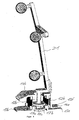
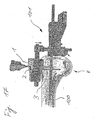
- FIG. 17 shows schematically the positioning of a cutting block 1 on a Thigh bone K according to the prior art.
- a guide rod 100 introduced into a bone K, wherein at the outer end of the guide rod 100 is a positioning mechanism 101 for positioning and holding the cutting block 1 is provided in a desired position. Is the cutting block 1 in the desired Position, so can be provided by provided in the cutting block 1 holes. 2
- Positioning pins 3, such as screws or nails or pins in the bone K be introduced for fixing the cutting block 1.
- the fixation of the Cutting block 1 on the bone K can be a preferably as perpendicular or easy to mechanical axis of the bone angled lying first cutting plane S0 means of a cutting tool 4, as shown schematically in Figs. 14A and 14B shown.
- the associated knee implant component to be able to position on the bone, further cuts in further to the cutting plane S0 obliquely extending or angled planes S1 to S4 generated be as shown in Figure 15.
- a second cutting block 10 on the first Cut level S0 placed and positioned by means of a suitable mechanism, with this second cutting block 10 more lateral cuts are made on the bone K, which by guiding the cutting tool 4 in the oblique or lateral Slots of the second cutting block 10 are generated.
- the reference star 21 is fixedly connected to the main body 22, on which a rotatable element 23 is mounted, wherein at the outer end of the rotatable member 23 has two plates 24a and 24b of different thickness are arranged, which in a guide slot 1a of the tibial cutting block shown in Figs. 12A to 12E or one of the guide slots II, III of the femoral cutting block shown in Figure 13 are inserted can.
- the section shown in Figure 14 of the inserted with the Device 20 connected cutting block navigated to the desired location of the bone K be where the cutting block 1 with fasteners 3 attached to the bone K. can be as shown in Figure 14A. With a cutting tool 4 can then a section in the desired cutting plane, as shown in Figure 14B, are generated.
- a second cutting block 10 such as schematically shown in Figure 15, are plugged and through in the second cutting block 10 provided guide slots can perform cuts in the levels S1 to S4 so that, for example, an artificial joint can be put on which with correct position of the cutting plane S0 to S4 is also correctly positioned.
- the inventive device for determining the position of a cutting block has a positioning element, such as a reference star with at least a reference point or marker whose position in space can be detected.
- a positioning element such as a reference star with at least a reference point or marker whose position in space can be detected.
- at the positioning element can be active and / or passive elements, emit or reflect suitable signals from appropriate recording devices, such as cameras, to capture the spatial position of the positioning element and be able to determine the associated device.
- a position determining element is provided on the device according to the invention, which is firmly connected to the positioning element and which with an instrument or a device such as a cutting block or other Device having a surface to be navigated, can be connected.
- the position determination element consists of a reference element, such as For example, a reference plate whose surface is attached to an area at can serve an instrument to be navigated and serves as a reference plane, according to the invention at least one pressure element or clamping element is provided, which it allows the abutment surface of the reference element against an area of a navigating instrument can be pressed when the positioning element is inserted into an opening or a slot.
- a reference element such as a reference plate whose surface is attached to an area at can serve an instrument to be navigated and serves as a reference plane
- at least one pressure element or clamping element is provided, which it allows the abutment surface of the reference element against an area of a navigating instrument can be pressed when the positioning element is inserted into an opening or a slot.
- the at least one inventive Pressure plate may be formed so that one or more pressure elements or pressure plates with an example produced by a spring or a clamping element Force be pushed away from the reference element, whereby the reference element in connection with the at least one prestressed pressure element in one Opening or a slot can be tightly clamped or pinched, regardless of whether the opening or the slot have a precisely predetermined thickness or slightly different from this predetermined thickness, for example. That by a Force biased pressure element can thus prevent the invention Positioning element due to a game in a precisely defined positional relationship to the connected to the positioning element instrument.
- the position determining element or a part thereof i. H. the reference element and / or the pressure element about an axis relative to the positioning element or reference star rotatable, the axis preferably parallel to a normal is on the reference plane determined by the reference element. It is also advantageous when these elements are displaceable, wherein advantageously the reference element so is formed such that a contact surface on the reference element, which is a reference plane forms, can only be moved within the reference plane.
- a positioning element is preferably a reference star with three arranged thereon passive markers provided for navigation through the position determining element formed reference plane can be used.
- the reference and / or pressure element is at least one in a cutting block insertable plate, with several individual preferably lying in a plane Plate elements can be used as a reference and / or pressure element.
- the Pressure element is preferably in a direction perpendicular to that through the reference element movable formed investment or reference plane.
- a part of the pressure element be formed so that, for example, in a recess of the reference element can work and, for example, about the same thickness as the Thickness of a plate used as a reference element, so that the reference element together can be inserted with the pressure element in a slot.
- the pressure element by a spring or biasing element with a Stressed force, which out of the plane defined by the reference element out acts and preferably perpendicular to this plane, so that when inserting the reference element with the pressure element in a slot, the pressure element due to Biasing element is moved so far away from the reference element until the pressure element and the reference member fixed to side surfaces of a slot or an opening abut and thus a firm and defined connection between the positioning element and the instrument.
- the biasing element can, for example formed by one or more springs, for example, a coil spring between the reference element and the pressure element is provided so that the spring must be compressed to the reference element on the pressure element or in a To move recess of the pressure element into it, whereby the spring has a restoring force generated, with which the reference element again pushed away from the pressure element is to by the interaction of the reference element with the pressure element for Example, a non-positive or positive connection with a slot, which provided on an instrument to be able to produce.
- the spring element can be designed as a compression spring, as well as a tension spring or as a leaf spring and should be provided on the device according to the invention so that the reference element of the pressure element is moved away.
- the biasing element or a spring element on the inventive Device be provided so that by the force generated by the biasing element a Inhibited rotational movement of a freely rotatable positioning element or reference star can be and prefers the positioning element or the reference star in a fixed position can be detected or locked.
- the invention in another aspect, relates to a system for positioning a cutting block with a device as described above and a cutting block, which has at least one slot which uses as a guide slot can be and in which the position-determining element and in particular a Plate can be inserted, which firmly with the positioning element or reference star connected is.
- the device described can also be used to navigate other instruments which are an opening or a slot for insertion of the position-determining element exhibit.
- the present invention enables the defined and backlash-free attachment a positioning element or reference star at a slot or opening an instrument, wherein the slot or the opening have different thicknesses can, and can be ensured by the invention that one by a Reference element formed reference level can be navigated when the distance of the Positioning element to the reference element or serving as a reference plane Contact surface of the device is defined and, for example, a constant set Has distance, with the pressure element used for clamping a secure attachment at openings or slots of different thickness, so that the inventive Device implemented in software as a pre-calibrated device can be. It is also possible that a serving as a reference plane bearing surface for Verification or verification of the position of a surface, such as a Cut to a bone, can be used.
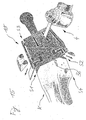
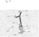
- Figures 1 and 2A to C show an inventive device 20 for determining the position of a cutting block 1 with a reference star 21, on which three as a reflective Ball surfaces formed markers 22a, 22b and 22c are attached.
- the reference star 21 is rotatable on the reference star holder 15 designed as an axle attached, which at its top and bottom plate-shaped closing elements 15a and 15b.
- the upper end element 15a shown in FIG. 1 prevents the connecting element 11 can be detached from the reference star holder 15.
- the reference star holder 15 protrudes through an opening of the pressing member 14 a and is on the Bottom connected to the lower end element 15b with the reference element 13a, whose underside serves as a reference plane.
- a spring 12a On top of the lower end 15b, a spring 12a is supported, which bears against the underside of the pressure element 14a pushes and thus pushes the pressure element 14a away from the reference element 13a.
- the Pressure element 14a is step-shaped and has a pressure plate 14e, which is pushed between two reference plates 13e and 13f of the reference element 13a can be as shown in Figure 2.
- a user may select the pressing member 14a and the reference member 13a between two fingers and by squeezing the elements 13a and 14a the spring 12a provided between these elements tension and the device in Insert a slot of a cutting block 1, so that after releasing the device 20 the pressure element 14a by the force of the spring 12a relative to the reference element 13a is moved up to the device fixed to the cutting block.
- 1 connect, wherein the positional relationship between the reference star 21 and by the Bottom of the reference element 13a formed reference plane remains constant, so that the Surface of the slot in the cutting block 1 abutting the reference plane by means of the Reference star 21 can be navigated. Due to the lower end element 14b acting spring force is the reference star 21 in the state shown in Figure 1 locked device according to the invention and can not be rotated.
- FIG 2C shows the device shown in Figures 1, 2A and 2B, wherein the pressure element 14a to allow easy cleaning of the device from the reference element 13a has been moved away.
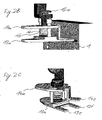
- FIGS. 3 to 5 show a second embodiment of the device according to the invention with a reference star 21, which has two rings 17a and 17b, the separated by a spacer 17c.
- the spacer 17c of the reference star 21 can between two clamping point forming latching elements 16a and 16b be connected to the reference element 13b.
- the reference element 13b is over two approximately vertically to the reference element 13b extending leaf springs 12b with a pressure element 14b, wherein, as shown in Figure 4, the pressing member 14b by a lateral displacement of the leaf springs 12b from the initial position shown in FIG can be moved so that the pressure plate 14e between the reference plates 13e and 13f of the reference element 13b is moved.
- the leaf springs 12b generate a restoring force the pressure element 14b relative to the reference element 13b, wherein also a Component of the restoring force perpendicular to the lower surface of the reference element 13b, which serves as a reference plane, whereby the shown in Figures 3 to 5 Device by the movement of the pressure plate 14e relative to the reference plates 13e and 13f can be attached without play to an opening or in a slot.
- FIGS. 6 to 8 A third embodiment of the device according to the invention is shown in FIGS. 6 to 8, wherein the pressure element 14c is approximately horizontal or parallel to the underside the reference element 13c extending leaf springs 12c with the reference element 13c is connected, again by the leaf springs 12c on the pressure plate 14e acting force can be generated, so that the pressure plate 14e from the out through the reference plates 13e and 13f of the reference element 13c can be moved to the reference star 21 fixed and in a defined positional relationship relative to the underside of the reference element 13a with an opening or a Gap to connect.
- the reference star 21 can be inserted by means of a ball pressure pin which can be pushed into the reference element 13c 16 are latched to the reference element 13c.
- FIGS. 9 to 11 show a fourth embodiment of the device according to the invention, wherein the reference star 21 with the reference element 13d in a similar manner as shown in the second embodiment can be locked.
- Unlike the Previous embodiments is not in the fourth embodiment by a separate spring biased pressure element provided because the play-free positioning the underside of the reference element 13d in an opening or a gap required Pressure force by the protruding from the reference element 13d elastic or spring elements 14d is generated, which due to their in the insertion direction existing bevel the insertion of the reference element 13d in a gap thereby allow the elastic or spring elements during insertion 12d are pressed into the plane of the reference element 13d and in the inserted Condition against one of the underside of the reference element 13d opposite Press the surface of an opening or a gap.
Landscapes
- Health & Medical Sciences (AREA)
- Surgery (AREA)
- Life Sciences & Earth Sciences (AREA)
- Heart & Thoracic Surgery (AREA)
- Molecular Biology (AREA)
- Oral & Maxillofacial Surgery (AREA)
- Engineering & Computer Science (AREA)
- Biomedical Technology (AREA)
- Veterinary Medicine (AREA)
- Medical Informatics (AREA)
- Nuclear Medicine, Radiotherapy & Molecular Imaging (AREA)
- Animal Behavior & Ethology (AREA)
- General Health & Medical Sciences (AREA)
- Public Health (AREA)
- Dentistry (AREA)
- Pathology (AREA)
- Surgical Instruments (AREA)
- Prostheses (AREA)
Abstract
Description
- Figuren 1 und 2A-C
- eine erste Ausführungsform einer erfindungsgemäßen Vorrichtung;
- Figuren 3 bis 5
- eine zweite Ausführungsform der erfindungsgemäßen Vorrichtung;
- Figuren 6 bis 8
- eine dritte Ausführungsform der erfindungsgemäßen Vorrichtung;
- Figuren 9 bis 11
- eine vierte Ausführungsform der erfindungemäßen Vorrichtung;
- Figuren 12A bis 12B
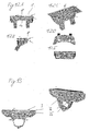
- verschiedene Ansichten eines tibialen Schneidblocks;
- Figur 13
- zwei Ansichten eines femoralen Schneidblocks;
- Figuren 14A und 14B
- das Schneiden eines Knochens mit einem positionierten Schneidblock;
- Figur 15
- das Schneiden der Schnittebenen S1 bis S6 mit einem zweiten Schneidblock;
- Figur 16
- eine bekannte Vorrichtung zur Positionierung eines Schneidblocks; und
- Figur 17
- die Positionierung eines Schneidblockes nach dem Stand der Technik;
Claims (7)
- Vorrichtung (20) zum Bestimmen der Position eines Schneidblockes (1) mit einem Positionierungselement (21) mit mindestens einem Referenzpunkt (22a, 22b, 22c), dessen räumliche Position erfasst werden kann und einem Positionsbestimmungselement (13, 14), wobei das Positionsbestimmungselement mindestens ein eine Anlageebene definierendes Referenzelement (13) und mindestens ein Andruckelement (14) aufweist.
- Vorrichtung nach Anspruch 1, wobei das Referenzelement (13) mindestens eine in einen Schneidblock (1) einsteckbare Platte ist.
- Vorrichtung nach einem der vorhergehenden Ansprüche, wobei das Andruckelement als elastisches Element oder Federelement (14d) ausgebildet ist oder durch ein elastisches oder Federelement (12) mit einer Kraft beaufschlagt wird.
- Vorrichtung nach einem der vorhergehenden Ansprüche, wobei eine Andruckplatte (14e) des Andruckelementes (14) in eine Plattenebene des Referenzelementes (13) bewegt werden kann.
- Vorrichtung nach einem der vorhergehenden Ansprüche, wobei das Positionierungselement (21) durch das. elastische Element oder Federelement (12) festgestellt oder arretiert werden kann.
- Vorrichtung nach einem der vorhergehenden Ansprüche, wobei das Positionierungselement ein Referenzstern (21) ist und bevorzugt mindestens drei Elemente (22a, 22b, 22c) mit reflektierender Oberfläche als Referenzpunkte aufweist.
- System zum Positionieren eines Schneidblockes (1) mit einer Vorrichtung (20) nach einem der vorhergehenden Ansprüche und einem Schneidblock (1).
Priority Applications (3)
| Application Number | Priority Date | Filing Date | Title |
|---|---|---|---|
| DE502004009884T DE502004009884D1 (de) | 2004-02-03 | 2004-02-03 | Vorrichtung zum Bestimmen der Position eines Schneidblocks |
| EP04002321A EP1561431B1 (de) | 2004-02-03 | 2004-02-03 | Vorrichtung zum Bestimmen der Position eines Schneidblocks |
| US11/050,421 US7497029B2 (en) | 2004-02-03 | 2005-02-03 | Device for determining the position of an incision block |
Applications Claiming Priority (1)
| Application Number | Priority Date | Filing Date | Title |
|---|---|---|---|
| EP04002321A EP1561431B1 (de) | 2004-02-03 | 2004-02-03 | Vorrichtung zum Bestimmen der Position eines Schneidblocks |
Publications (2)
| Publication Number | Publication Date |
|---|---|
| EP1561431A1 true EP1561431A1 (de) | 2005-08-10 |
| EP1561431B1 EP1561431B1 (de) | 2009-08-12 |
Family
ID=35796953
Family Applications (1)
| Application Number | Title | Priority Date | Filing Date |
|---|---|---|---|
| EP04002321A Expired - Lifetime EP1561431B1 (de) | 2004-02-03 | 2004-02-03 | Vorrichtung zum Bestimmen der Position eines Schneidblocks |
Country Status (3)
| Country | Link |
|---|---|
| US (1) | US7497029B2 (de) |
| EP (1) | EP1561431B1 (de) |
| DE (1) | DE502004009884D1 (de) |
Cited By (3)
| Publication number | Priority date | Publication date | Assignee | Title |
|---|---|---|---|---|
| DE102006035602A1 (de) * | 2006-07-31 | 2008-02-07 | Plus Orthopedics Ag | Klammer zur Befestigung chirurgischer Operationshilfsmittel, Stellorgan für eine derartige Klammer und eine Anordnung umfassend ein Stellorgan und eine Klammer |
| EP2160986A1 (de) | 2008-09-05 | 2010-03-10 | BrainLAB AG | Vorrichtung zur Befestigung einer Markervorrichtung an einem Knochen |
| EP1976446A4 (de) * | 2006-01-25 | 2015-04-15 | Orthosoft Inc | Cas-system für kondylusmessung |
Families Citing this family (47)
| Publication number | Priority date | Publication date | Assignee | Title |
|---|---|---|---|---|
| JP4726032B2 (ja) * | 2000-08-31 | 2011-07-20 | スミス アンド ネフュー オーソペディックス アーゲー | 体肢の力学軸の位置を検出する方法及び装置 |
| US7998062B2 (en) | 2004-03-29 | 2011-08-16 | Superdimension, Ltd. | Endoscope structures and techniques for navigating to a target in branched structure |
| DE10306793A1 (de) * | 2002-05-21 | 2003-12-04 | Plus Endoprothetik Ag Rotkreuz | Anordnung und Verfahren zur intraoperativen Festlegung der Lage eines Gelenkersatzimplantats |
| US8057482B2 (en) * | 2003-06-09 | 2011-11-15 | OrthAlign, Inc. | Surgical orientation device and method |
| US7559931B2 (en) * | 2003-06-09 | 2009-07-14 | OrthAlign, Inc. | Surgical orientation system and method |
| EP2316328B1 (de) * | 2003-09-15 | 2012-05-09 | Super Dimension Ltd. | Umhüllungsvorrichtung zur Fixierung von Bronchoskopen |
| ATE438335T1 (de) | 2003-09-15 | 2009-08-15 | Super Dimension Ltd | System aus zubehör zur verwendung mit bronchoskopen |
| US8764725B2 (en) | 2004-02-09 | 2014-07-01 | Covidien Lp | Directional anchoring mechanism, method and applications thereof |
| US7182767B2 (en) * | 2004-05-19 | 2007-02-27 | Howmedica Osteonics Corp. | Navigated lateral/medial femoral resection guide |
| US8192449B2 (en) * | 2005-10-25 | 2012-06-05 | Brainlab Ag | Non-penetrating fixing device |
| US20080161824A1 (en) * | 2006-12-27 | 2008-07-03 | Howmedica Osteonics Corp. | System and method for performing femoral sizing through navigation |
| DE102007011568A1 (de) * | 2007-03-08 | 2008-09-11 | Cas Innovations Ag | Medizinische Klemme, insbesondere Wirbelsäulen-Klemme |
| US8905920B2 (en) | 2007-09-27 | 2014-12-09 | Covidien Lp | Bronchoscope adapter and method |
| US9575140B2 (en) | 2008-04-03 | 2017-02-21 | Covidien Lp | Magnetic interference detection system and method |
| US8473032B2 (en) | 2008-06-03 | 2013-06-25 | Superdimension, Ltd. | Feature-based registration method |
| US8218847B2 (en) | 2008-06-06 | 2012-07-10 | Superdimension, Ltd. | Hybrid registration method |
| US8932207B2 (en) | 2008-07-10 | 2015-01-13 | Covidien Lp | Integrated multi-functional endoscopic tool |
| CA2731436C (en) * | 2008-07-24 | 2019-09-24 | OrthAlign, Inc. | Systems and methods for joint replacement |
| ES2750264T3 (es) | 2008-09-10 | 2020-03-25 | Orthalign Inc | Sistemas de cirugía de la cadera |
| US8611984B2 (en) | 2009-04-08 | 2013-12-17 | Covidien Lp | Locatable catheter |
| ATE515240T1 (de) * | 2009-05-06 | 2011-07-15 | Brainlab Ag | Werkzeug zum erfassen von ebenen eines knochens und zugeordnetes datenverarbeitungsverfahren |
| US9339226B2 (en) * | 2010-01-21 | 2016-05-17 | OrthAlign, Inc. | Systems and methods for joint replacement |
| US8118815B2 (en) | 2009-07-24 | 2012-02-21 | OrthAlign, Inc. | Systems and methods for joint replacement |
| US10869771B2 (en) | 2009-07-24 | 2020-12-22 | OrthAlign, Inc. | Systems and methods for joint replacement |
| US10537392B2 (en) | 2010-03-03 | 2020-01-21 | Brainlab Ag | Method for enabling medical navigation with minimised invasiveness |
| US10582834B2 (en) | 2010-06-15 | 2020-03-10 | Covidien Lp | Locatable expandable working channel and method |
| US9549742B2 (en) | 2012-05-18 | 2017-01-24 | OrthAlign, Inc. | Devices and methods for knee arthroplasty |
| US9649160B2 (en) | 2012-08-14 | 2017-05-16 | OrthAlign, Inc. | Hip replacement navigation system and method |
| US9151587B2 (en) * | 2013-11-11 | 2015-10-06 | General Electric Company | Bucket tip shroud measurement fixture and method of measuring bucket tip shroud orientation |
| US10952593B2 (en) | 2014-06-10 | 2021-03-23 | Covidien Lp | Bronchoscope adapter |
| US9539679B2 (en) * | 2014-07-31 | 2017-01-10 | The Boeing Company | Alignment tool |
| US10363149B2 (en) | 2015-02-20 | 2019-07-30 | OrthAlign, Inc. | Hip replacement navigation system and method |
| US10426555B2 (en) | 2015-06-03 | 2019-10-01 | Covidien Lp | Medical instrument with sensor for use in a system and method for electromagnetic navigation |
| US10478254B2 (en) | 2016-05-16 | 2019-11-19 | Covidien Lp | System and method to access lung tissue |
| US10638952B2 (en) | 2016-10-28 | 2020-05-05 | Covidien Lp | Methods, systems, and computer-readable media for calibrating an electromagnetic navigation system |
| US10418705B2 (en) | 2016-10-28 | 2019-09-17 | Covidien Lp | Electromagnetic navigation antenna assembly and electromagnetic navigation system including the same |
| US10517505B2 (en) | 2016-10-28 | 2019-12-31 | Covidien Lp | Systems, methods, and computer-readable media for optimizing an electromagnetic navigation system |
| US10751126B2 (en) | 2016-10-28 | 2020-08-25 | Covidien Lp | System and method for generating a map for electromagnetic navigation |
| US10446931B2 (en) | 2016-10-28 | 2019-10-15 | Covidien Lp | Electromagnetic navigation antenna assembly and electromagnetic navigation system including the same |
| US10615500B2 (en) | 2016-10-28 | 2020-04-07 | Covidien Lp | System and method for designing electromagnetic navigation antenna assemblies |
| US10792106B2 (en) | 2016-10-28 | 2020-10-06 | Covidien Lp | System for calibrating an electromagnetic navigation system |
| US10722311B2 (en) | 2016-10-28 | 2020-07-28 | Covidien Lp | System and method for identifying a location and/or an orientation of an electromagnetic sensor based on a map |
| AU2018236220A1 (en) | 2017-03-14 | 2019-09-26 | OrthAlign, Inc. | Hip replacement navigation systems and methods |
| WO2018169980A1 (en) | 2017-03-14 | 2018-09-20 | OrthAlign, Inc. | Soft tissue measurement & balancing systems and methods |
| US11219489B2 (en) | 2017-10-31 | 2022-01-11 | Covidien Lp | Devices and systems for providing sensors in parallel with medical tools |
| EP3793454B1 (de) * | 2018-05-18 | 2026-04-01 | Smith & Nephew Inc. | System zur verfolgung von resektionsebenen |
| US20240307129A1 (en) * | 2021-08-04 | 2024-09-19 | University Of Florida Research Foundation, Incorporated | Neurosurgical navigation system reference array apparatus |
Citations (5)
| Publication number | Priority date | Publication date | Assignee | Title |
|---|---|---|---|---|
| WO2000041635A1 (fr) * | 1999-01-18 | 2000-07-20 | Aesculap | Implant avec support de marqueur et outil de pose |
| EP1249207A2 (de) * | 1993-02-12 | 2002-10-16 | George S. Allen | Markierung als Bezugspunkt |
| FR2830743A1 (fr) * | 2001-10-11 | 2003-04-18 | Surgiview Sa | Stylo palpeur a enclenchement d'emission au contact d'une surface |
| US6551325B2 (en) * | 2000-09-26 | 2003-04-22 | Brainlab Ag | Device, system and method for determining the position of an incision block |
| WO2004017842A2 (en) * | 2002-08-23 | 2004-03-04 | Orthosoft Inc. | Surgical universal positioning block and tool guide |
Family Cites Families (17)
| Publication number | Priority date | Publication date | Assignee | Title |
|---|---|---|---|---|
| US5213112A (en) * | 1992-01-29 | 1993-05-25 | Pfizer Hospital Products Group, Inc. | Tension meter for orthopedic surgery |
| US5445642A (en) * | 1992-09-01 | 1995-08-29 | Depuy Inc. | Method for installing a femoral component |
| US5417694A (en) * | 1993-11-08 | 1995-05-23 | Smith & Nephew Richards Inc. | Distal femoral cutting guide apparatus with anterior or posterior referencing for use in knee joint replacement surgery |
| US5601566A (en) * | 1994-02-22 | 1997-02-11 | Osteonics Corp. | Method and apparatus for the alignment of a femoral knee prosthesis |
| US6695848B2 (en) * | 1994-09-02 | 2004-02-24 | Hudson Surgical Design, Inc. | Methods for femoral and tibial resection |
| US5910143A (en) * | 1994-12-16 | 1999-06-08 | Exactech, Inc. | Intramedullary alignment guide tool |
| US6073360A (en) * | 1997-01-22 | 2000-06-13 | Js Research And Development, Inc. | Instrument mount with spring-loaded clamp |
| US6059531A (en) * | 1998-06-19 | 2000-05-09 | Tai; Jen-Lung David | Impeller and fan blade attachment assembly |
| US6514259B2 (en) * | 2001-02-02 | 2003-02-04 | Carnegie Mellon University | Probe and associated system and method for facilitating planar osteotomy during arthoplasty |
| US7993353B2 (en) * | 2002-06-04 | 2011-08-09 | Brainlab Ag | Medical tracking system with universal interface |
| US7029477B2 (en) * | 2002-12-20 | 2006-04-18 | Zimmer Technology, Inc. | Surgical instrument and positioning method |
| DE20303499U1 (de) * | 2003-02-26 | 2003-04-30 | Aesculap AG & Co. KG, 78532 Tuttlingen | Patella-Referenzvorrichtung |
| FR2852223B1 (fr) | 2003-03-11 | 2005-06-10 | Perception Raisonnement Action En Medecine | Instrument de reperage de la position d'un plan de coupe |
| US7111863B2 (en) * | 2003-07-15 | 2006-09-26 | Ward Robert J | Trailer alignment aid with universal mounting device |
| US20050215888A1 (en) * | 2004-03-05 | 2005-09-29 | Grimm James E | Universal support arm and tracking array |
| TWI272163B (en) * | 2005-07-26 | 2007-02-01 | Benq Corp | Prying tools |
| US7337515B2 (en) * | 2006-01-25 | 2008-03-04 | Breaching Technologies, Inc. | Hybrid breaching bar |
-
2004
- 2004-02-03 DE DE502004009884T patent/DE502004009884D1/de not_active Expired - Lifetime
- 2004-02-03 EP EP04002321A patent/EP1561431B1/de not_active Expired - Lifetime
-
2005
- 2005-02-03 US US11/050,421 patent/US7497029B2/en active Active
Patent Citations (5)
| Publication number | Priority date | Publication date | Assignee | Title |
|---|---|---|---|---|
| EP1249207A2 (de) * | 1993-02-12 | 2002-10-16 | George S. Allen | Markierung als Bezugspunkt |
| WO2000041635A1 (fr) * | 1999-01-18 | 2000-07-20 | Aesculap | Implant avec support de marqueur et outil de pose |
| US6551325B2 (en) * | 2000-09-26 | 2003-04-22 | Brainlab Ag | Device, system and method for determining the position of an incision block |
| FR2830743A1 (fr) * | 2001-10-11 | 2003-04-18 | Surgiview Sa | Stylo palpeur a enclenchement d'emission au contact d'une surface |
| WO2004017842A2 (en) * | 2002-08-23 | 2004-03-04 | Orthosoft Inc. | Surgical universal positioning block and tool guide |
Cited By (4)
| Publication number | Priority date | Publication date | Assignee | Title |
|---|---|---|---|---|
| EP1976446A4 (de) * | 2006-01-25 | 2015-04-15 | Orthosoft Inc | Cas-system für kondylusmessung |
| DE102006035602A1 (de) * | 2006-07-31 | 2008-02-07 | Plus Orthopedics Ag | Klammer zur Befestigung chirurgischer Operationshilfsmittel, Stellorgan für eine derartige Klammer und eine Anordnung umfassend ein Stellorgan und eine Klammer |
| EP2160986A1 (de) | 2008-09-05 | 2010-03-10 | BrainLAB AG | Vorrichtung zur Befestigung einer Markervorrichtung an einem Knochen |
| US9095376B2 (en) | 2008-09-05 | 2015-08-04 | Brainlab Ag | Device for fastening a marker device to a bone |
Also Published As
| Publication number | Publication date |
|---|---|
| DE502004009884D1 (de) | 2009-09-24 |
| EP1561431B1 (de) | 2009-08-12 |
| US20050190380A1 (en) | 2005-09-01 |
| US7497029B2 (en) | 2009-03-03 |
Similar Documents
| Publication | Publication Date | Title |
|---|---|---|
| EP1561431B1 (de) | Vorrichtung zum Bestimmen der Position eines Schneidblocks | |
| EP1413258B1 (de) | Vorrichtung und Verfahren zum Kalibrieren eines Elements | |
| EP1190676B1 (de) | Vorrichtung zum Bestimmen der Position eines Schneidblocks | |
| DE60214290T2 (de) | Hilfsvorrichtung zur Positionierung eines Oberarmteils einer Ellenbogenprothese | |
| EP1470787B1 (de) | Vorrichtung zur Vorbereitung einer Femurkondyle | |
| EP1596749B1 (de) | Patella-referenzvorrichtung | |
| EP0919195B1 (de) | Instrumentenbaukasten für Kniegelenkprothesen | |
| DE60216667T2 (de) | Vorrichtung zur Positionierung der Schnittebene einer Knochensägenführung | |
| EP1470786A1 (de) | Vorrichtung zur Vorbereitung einer Femurkondyle | |
| EP1442714A1 (de) | Zielhilfe für Rückenwirbel | |
| EP2123229A1 (de) | Verbindung von Schneidblöcken | |
| EP1470788A1 (de) | Vorrichtung zur Festlegung von Knochenschnitten | |
| DE3842645A1 (de) | Saegelehrensystem | |
| EP3075330B1 (de) | Medizinische führungsvorrichtung | |
| EP1543784B1 (de) | Resektionsschnittlehre und Verfahren zur Positionierung einer Resektionsschnittlehre | |
| EP1413257B1 (de) | Vorrichtung zum Positionieren eines Elements, zum Beispiel in der Wirbelsäule | |
| EP1771116A1 (de) | Instrumentarium und verfahren zum bearbeiten eines zervikalen wirbelkörpers | |
| DE29614349U1 (de) | Anordnung zum Einsetzen einer femoralen Knie-Gleitflächen-Endoprothese | |
| DE102007055456B4 (de) | Chirurgische Referenzierungseinheit und chirurgisches Navigationssystem | |
| WO2017157767A1 (de) | Operationsvorrichtung für eine operation des menschlichen knies | |
| EP1667596A1 (de) | Knochenfester lokator und optisches navigationssystem | |
| EP1663019B1 (de) | Vorrichtung zur bestimmung des winkels zwischen femur und tibia | |
| DE19716300C1 (de) | System zur Abbildung der natürlichen Torquiertheit zwischen den Kondylen des natürlichen Kniegelenks und dem Gelenkkopf des natürlichen Hüftgelenkes | |
| EP1504734B1 (de) | Einsetzinstrument für ein Paar von Schlittenprothesen | |
| EP3095398A1 (de) | Patientenspezifisches instrument zur referenzierung von körperteilen |
Legal Events
| Date | Code | Title | Description |
|---|---|---|---|
| PUAI | Public reference made under article 153(3) epc to a published international application that has entered the european phase |
Free format text: ORIGINAL CODE: 0009012 |
|
| 17P | Request for examination filed |
Effective date: 20040203 |
|
| AK | Designated contracting states |
Kind code of ref document: A1 Designated state(s): AT BE BG CH CY CZ DE DK EE ES FI FR GB GR HU IE IT LI LU MC NL PT RO SE SI SK TR |
|
| AX | Request for extension of the european patent |
Extension state: AL LT LV MK |
|
| AKX | Designation fees paid |
Designated state(s): DE FR GB IT |
|
| 17Q | First examination report despatched |
Effective date: 20060524 |
|
| RAP1 | Party data changed (applicant data changed or rights of an application transferred) |
Owner name: BRAINLAB AG |
|
| GRAP | Despatch of communication of intention to grant a patent |
Free format text: ORIGINAL CODE: EPIDOSNIGR1 |
|
| GRAS | Grant fee paid |
Free format text: ORIGINAL CODE: EPIDOSNIGR3 |
|
| GRAA | (expected) grant |
Free format text: ORIGINAL CODE: 0009210 |
|
| AK | Designated contracting states |
Kind code of ref document: B1 Designated state(s): DE FR GB IT |
|
| REG | Reference to a national code |
Ref country code: GB Ref legal event code: FG4D Free format text: NOT ENGLISH |
|
| REF | Corresponds to: |
Ref document number: 502004009884 Country of ref document: DE Date of ref document: 20090924 Kind code of ref document: P |
|
| PLBE | No opposition filed within time limit |
Free format text: ORIGINAL CODE: 0009261 |
|
| STAA | Information on the status of an ep patent application or granted ep patent |
Free format text: STATUS: NO OPPOSITION FILED WITHIN TIME LIMIT |
|
| 26N | No opposition filed |
Effective date: 20100517 |
|
| PG25 | Lapsed in a contracting state [announced via postgrant information from national office to epo] |
Ref country code: IT Free format text: LAPSE BECAUSE OF FAILURE TO SUBMIT A TRANSLATION OF THE DESCRIPTION OR TO PAY THE FEE WITHIN THE PRESCRIBED TIME-LIMIT Effective date: 20090812 |
|
| REG | Reference to a national code |
Ref country code: DE Ref legal event code: R082 Ref document number: 502004009884 Country of ref document: DE Representative=s name: SCHWABE SANDMAIR MARX, DE |
|
| REG | Reference to a national code |
Ref country code: DE Ref legal event code: R081 Ref document number: 502004009884 Country of ref document: DE Owner name: BRAINLAB AG, DE Free format text: FORMER OWNER: BRAINLAB AG, 85622 FELDKIRCHEN, DE Effective date: 20131104 Ref country code: DE Ref legal event code: R082 Ref document number: 502004009884 Country of ref document: DE Representative=s name: SCHWABE SANDMAIR MARX, DE Effective date: 20131104 Ref country code: DE Ref legal event code: R082 Ref document number: 502004009884 Country of ref document: DE Representative=s name: SCHWABE SANDMAIR MARX PATENTANWAELTE RECHTSANW, DE Effective date: 20131104 |
|
| REG | Reference to a national code |
Ref country code: FR Ref legal event code: PLFP Year of fee payment: 13 |
|
| REG | Reference to a national code |
Ref country code: FR Ref legal event code: PLFP Year of fee payment: 14 |
|
| REG | Reference to a national code |
Ref country code: DE Ref legal event code: R082 Ref document number: 502004009884 Country of ref document: DE Representative=s name: SSM SANDMAIR PATENTANWAELTE RECHTSANWALT PARTN, DE Ref country code: DE Ref legal event code: R082 Ref document number: 502004009884 Country of ref document: DE Representative=s name: SCHWABE SANDMAIR MARX PATENTANWAELTE RECHTSANW, DE Ref country code: DE Ref legal event code: R081 Ref document number: 502004009884 Country of ref document: DE Owner name: BRAINLAB AG, DE Free format text: FORMER OWNER: BRAINLAB AG, 85622 FELDKIRCHEN, DE |
|
| REG | Reference to a national code |
Ref country code: FR Ref legal event code: CA Effective date: 20170706 |
|
| REG | Reference to a national code |
Ref country code: FR Ref legal event code: PLFP Year of fee payment: 15 |
|
| PGFP | Annual fee paid to national office [announced via postgrant information from national office to epo] |
Ref country code: FR Payment date: 20230220 Year of fee payment: 20 |
|
| PGFP | Annual fee paid to national office [announced via postgrant information from national office to epo] |
Ref country code: GB Payment date: 20230220 Year of fee payment: 20 Ref country code: DE Payment date: 20230216 Year of fee payment: 20 |
|
| P01 | Opt-out of the competence of the unified patent court (upc) registered |
Effective date: 20230428 |
|
| REG | Reference to a national code |
Ref country code: DE Ref legal event code: R071 Ref document number: 502004009884 Country of ref document: DE |
|
| REG | Reference to a national code |
Ref country code: GB Ref legal event code: PE20 Expiry date: 20240202 |
|
| PG25 | Lapsed in a contracting state [announced via postgrant information from national office to epo] |
Ref country code: GB Free format text: LAPSE BECAUSE OF EXPIRATION OF PROTECTION Effective date: 20240202 |