EP1561526A1 - Outil de pose de rivets dans des composants - Google Patents
Outil de pose de rivets dans des composants Download PDFInfo
- Publication number
- EP1561526A1 EP1561526A1 EP05001307A EP05001307A EP1561526A1 EP 1561526 A1 EP1561526 A1 EP 1561526A1 EP 05001307 A EP05001307 A EP 05001307A EP 05001307 A EP05001307 A EP 05001307A EP 1561526 A1 EP1561526 A1 EP 1561526A1
- Authority
- EP
- European Patent Office
- Prior art keywords
- variable
- mass element
- rivet
- components according
- rivet elements
- Prior art date
- Legal status (The legal status is an assumption and is not a legal conclusion. Google has not performed a legal analysis and makes no representation as to the accuracy of the status listed.)
- Granted
Links
Images



Classifications
-
- B—PERFORMING OPERATIONS; TRANSPORTING
- B21—MECHANICAL METAL-WORKING WITHOUT ESSENTIALLY REMOVING MATERIAL; PUNCHING METAL
- B21J—FORGING; HAMMERING; PRESSING METAL; RIVETING; FORGE FURNACES
- B21J15/00—Riveting
- B21J15/10—Riveting machines
- B21J15/14—Riveting machines specially adapted for riveting specific articles, e.g. brake lining machines
- B21J15/142—Aerospace structures
-
- B—PERFORMING OPERATIONS; TRANSPORTING
- B21—MECHANICAL METAL-WORKING WITHOUT ESSENTIALLY REMOVING MATERIAL; PUNCHING METAL
- B21J—FORGING; HAMMERING; PRESSING METAL; RIVETING; FORGE FURNACES
- B21J15/00—Riveting
- B21J15/10—Riveting machines
- B21J15/14—Riveting machines specially adapted for riveting specific articles, e.g. brake lining machines
-
- B—PERFORMING OPERATIONS; TRANSPORTING
- B21—MECHANICAL METAL-WORKING WITHOUT ESSENTIALLY REMOVING MATERIAL; PUNCHING METAL
- B21J—FORGING; HAMMERING; PRESSING METAL; RIVETING; FORGE FURNACES
- B21J15/00—Riveting
- B21J15/10—Riveting machines
- B21J15/16—Drives for riveting machines; Transmission means therefor
- B21J15/24—Drives for riveting machines; Transmission means therefor operated by electro-magnets
-
- Y—GENERAL TAGGING OF NEW TECHNOLOGICAL DEVELOPMENTS; GENERAL TAGGING OF CROSS-SECTIONAL TECHNOLOGIES SPANNING OVER SEVERAL SECTIONS OF THE IPC; TECHNICAL SUBJECTS COVERED BY FORMER USPC CROSS-REFERENCE ART COLLECTIONS [XRACs] AND DIGESTS
- Y10—TECHNICAL SUBJECTS COVERED BY FORMER USPC
- Y10T—TECHNICAL SUBJECTS COVERED BY FORMER US CLASSIFICATION
- Y10T29/00—Metal working
- Y10T29/49—Method of mechanical manufacture
- Y10T29/49826—Assembling or joining
- Y10T29/49908—Joining by deforming
- Y10T29/49938—Radially expanding part in cavity, aperture, or hollow body
- Y10T29/49943—Riveting
-
- Y—GENERAL TAGGING OF NEW TECHNOLOGICAL DEVELOPMENTS; GENERAL TAGGING OF CROSS-SECTIONAL TECHNOLOGIES SPANNING OVER SEVERAL SECTIONS OF THE IPC; TECHNICAL SUBJECTS COVERED BY FORMER USPC CROSS-REFERENCE ART COLLECTIONS [XRACs] AND DIGESTS
- Y10—TECHNICAL SUBJECTS COVERED BY FORMER USPC
- Y10T—TECHNICAL SUBJECTS COVERED BY FORMER US CLASSIFICATION
- Y10T29/00—Metal working
- Y10T29/49—Method of mechanical manufacture
- Y10T29/49826—Assembling or joining
- Y10T29/49947—Assembling or joining by applying separate fastener
- Y10T29/49954—Fastener deformed after application
- Y10T29/49956—Riveting
-
- Y—GENERAL TAGGING OF NEW TECHNOLOGICAL DEVELOPMENTS; GENERAL TAGGING OF CROSS-SECTIONAL TECHNOLOGIES SPANNING OVER SEVERAL SECTIONS OF THE IPC; TECHNICAL SUBJECTS COVERED BY FORMER USPC CROSS-REFERENCE ART COLLECTIONS [XRACs] AND DIGESTS
- Y10—TECHNICAL SUBJECTS COVERED BY FORMER USPC
- Y10T—TECHNICAL SUBJECTS COVERED BY FORMER US CLASSIFICATION
- Y10T29/00—Metal working
- Y10T29/53—Means to assemble or disassemble
- Y10T29/53039—Means to assemble or disassemble with control means energized in response to activator stimulated by condition sensor
- Y10T29/53061—Responsive to work or work-related machine element
- Y10T29/53065—Responsive to work or work-related machine element with means to fasten by deformation
-
- Y—GENERAL TAGGING OF NEW TECHNOLOGICAL DEVELOPMENTS; GENERAL TAGGING OF CROSS-SECTIONAL TECHNOLOGIES SPANNING OVER SEVERAL SECTIONS OF THE IPC; TECHNICAL SUBJECTS COVERED BY FORMER USPC CROSS-REFERENCE ART COLLECTIONS [XRACs] AND DIGESTS
- Y10—TECHNICAL SUBJECTS COVERED BY FORMER USPC
- Y10T—TECHNICAL SUBJECTS COVERED BY FORMER US CLASSIFICATION
- Y10T29/00—Metal working
- Y10T29/53—Means to assemble or disassemble
- Y10T29/53709—Overedge assembling means
- Y10T29/5377—Riveter
Definitions
- the invention relates to a device for fixing rivet elements in components according to the preamble of claim 1.
- DE 43 05 406 A1 discloses a so-called screw insertion device. and waistband system of which the respective connecting element in the component insertion entrainment element in horizontal guides to the component and from can be moved this way.
- the drive of the driving element so be designed that fasteners in component holes under compliance predefined press fits can be safely inserted and reshaped.
- the impact energy of the position-variable mass element is changeable, is a high flexibility in the adaptation of the achievable impact energy to different Enables boundary conditions that ensures a reduction, in the In the best case, only a single stroke for the deformation of a rivet element in the is required for connecting components. This reduces noise nuisance especially the mechanical stress of the rivet adapter and the him leading working robot.
- the impact energy can be determined by the parameter acceleration of the position variable mass element, length of the acceleration section of this Mass element or its mass are influenced, depending on flexibility the adaptation only individual or all these parameters are considered. by virtue of the fact that these parameters are easily changeable leads to this also to an uncomplicated influencing of the impact energy of the variable position Mass element.
- a particularly advantageous development of the invention results when the Impact energy depending on specific properties of the connected Components and / or specific properties of the rivet elements and / or of The location of the rivet adapter in the room to be determined, because precisely these parameters decisive influence on the required deformation energy and thus ultimately to have the impact energy to be generated.
- the position variable mass element within the rivet adapter horizontal is arranged movable, is a structurally simple way a precise Acceleration of a precisely defined mass allows, so ultimately the impact energy is precisely adjustable. Due to the sometimes very high accelerations It is also of particular interest to have a compact form of the to ensure accelerating mass element. This will be easy achieved in that the mass element only of an additional weight and a this associated, the rivet element deforming plunger and an at least these elements receiving horizontally movable support frame is formed.
- the rivet adapter also accommodates a clamping unit which, on the one hand, after Passing through the acceleration section a defined delay of the linear guide the position variable mass element causes and also the Movement of the position-variable mass element after contact with the Brake rivet decelerates.
- the braking of the linear guide and the position variable Masseimplantations can in the simplest by pneumatic clamping respectively.
- the mass element in an advantageous embodiment of the invention by electrically operated linear motors moved horizontally within the rivet adapter.
- the position variable mass element is a linear guide system is assigned, the displacement measuring system of a known per se Sensor tappable ruler is formed, with the ruler in the simplest case integrated directly into the guide rails of the position-variable mass element is.
- the Nietadapter a control and Assign the arithmetic unit, editable in the executable calculation algorithms are stored, taking into account the different input data the required impact energy and the size of the individual parameters, such as the mass of the variable position mass element, its acceleration and the length of the Determine acceleration distance.
- control and computing unit so be executed that the output signals generated in it directly the setting causes the various parameters in the rivet adapter.
- the tax and Computing unit also be associated with a display monitor in such a way that the Operator of the rivet setting workstation taking into account the various of the system Input data and the determined output data are displayed visually.
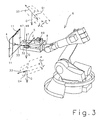
- a rivet setting work station 1 which essentially consists of a first, a position fixing adapter 3 for preferably rivet elements 4 receiving pivotally Working robot 2 and another rivet adapter according to the invention 5 pivotally leading working robot 6 is formed.
- the segments 7, 8 of the working robot 2, 6 to arbitrarily in Space arranged pivot axes 9, 10 pivotally, so that of the respective working robot 2, 6 guided Siegfixieradapter 2 and the Nietadapter. 5 take any positions within the working areas of the working robot 2, 6 can.
- the work areas of both work robots 2, 6 are so coordinated, that they work together in at least part of their radius of action can.
- the Nietsetzarbeitsstadion shown are 1 associated with each other to be joined components 11, so that the position fixing adapter. 3 and the rivet adapter 5 in the introduction and fixation of rivet elements 4 in the can be cooperated with each other components 11.
- the at the front-side segment 7 of the first working robot 2 pivotally arranged Lüfixieradapter 3 be designed so that its front Adaptierech 12th both tools 13 for introducing holes 14 in the to be connected Receive components 11 and the rivet elements 4 for connecting the components 11 can.
- the adaptation unit 12 works with corresponding tool and connector store together (not shown), of which one hand 13 different tools are removed and returned to this
- the adaptation unit 12 can have a wide variety of rivet elements 4 can be supplied.
- the adaptation unit 12 of the position fixing adapter 3 passed a rivet 4, which this by pivoting the segments 7 of the working robot 2 in one of the to be connected Inserting components 11 passing holes 14 in such a way that the Head 15 of the rivet 4 flush with the, the Lüfixieradapter 3 assigned Component 11 is present. It is within the scope of the invention that the adaptation unit 12 can also accommodate a plurality of rivet elements 4, so that at the same time several rivet elements 4 inserted into the corresponding holes 14 and fixed in this position can be.
- the segments 7 of the position fixing adapter 3 receiving working robot 2 in the working position in position are fixed and only the adapting unit 12, for example, designed to be horizontally displaceable is, so that first the tool 13, the bore 14 edit or manufacture and then the insertion of the rivet 4 can take place.
- the support frame 16 of the rivet adapter 5 is shown in FIG the simplest case by means of screw rotatably with the adapter flange 17th the front-side segment 8 of the corresponding working robot 6 is connected, so that the rivet adapter 5 by pivoting the individual segments 8 of the Working robot 6 to the respective pivot axes 10 precisely in the work area of the working robot 6 can be performed.
- the rotationally fixed to the working robot. 6 connected support frame 16 of the rivet adapter 5 are in its outer edge regions Assigned as a pneumatic cylinder 18 performed adjusting 19, the piston rod side with fixed to an intermediate frame 21 of the Nietadapters 5 Stellflanschen 20 are connected.
- the intermediate frame 21 is thus in the Nietadapter.
- the intermediate frame 21 guide rails 24 are assigned to which another support frame 25 is arranged horizontally movable.
- the horizontal one Movability of the support frame 25 is made possible by adjusting means 27, which are designed as electrically operated linear motors 26 and those on the intermediate frame 21 are fixed, with which the linear motors 26 leading and supporting stators 28 below the support frame 25 along the intermediate frame 21 extend and are fixed to this.
- adjusting means 27 which are designed as electrically operated linear motors 26 and those on the intermediate frame 21 are fixed, with which the linear motors 26 leading and supporting stators 28 below the support frame 25 along the intermediate frame 21 extend and are fixed to this.
- the relative to the intermediate frame 21 movable support frame 25 takes at least one additional weight 31 and in its front region a plunger 32nd on, wherein the plunger 32 is arranged on the support frame 25, that it at its horizontal movement 29 in the direction of the pressure piston sleeve 23 enforce this and can impinge on the associated end of the rivet 4.
- impact energy 33 there leads at the moment of impact of the plunger 32 on the rivet 4 the plunger 32 inherent energy, hereinafter referred to as impact energy 33, too a deformation of the rivet 4 in such a way that the plunger 32 associated Upset and thus a firm connection of the rivet 4 permeated components 11 is achieved.
- impact energy 33 there leads at the moment of impact of the plunger 32 on the rivet 4 the plunger 32 inherent energy, hereinafter referred to as impact energy 33, too a deformation of the rivet 4 in such a way that the plunger 32 associated Upset and thus a firm connection of the rivet 4 permeated components 11 is achieved.
- the components to be connected 11 associated area takes the Additional frame 21 also has a clamping unit 35, which has at least one Stop element 36 has, which on the one hand from the linear motors 26 caused horizontal movement 30 of the mass element 34 limited and their Stop element 36 in the simplest case pneumatically the mass element 34 after collision of the plunger 32 holds on the rivet 4, so that a Springback of the mass element 34 and a repeated contact of the Rivet element 4 is avoided.
- the pneumatic fixation of the mass element 34 may be carried out in the simplest case so that the additional weight 31 by generating a negative pressure in the region of the stop element 36 thereof is sucked.
- clamping unit 35 the mass element 34 also at another location can fix.
- the deceleration effect of the variable-position mass element 34 can also be increased by the fact that the thrust finger 29 in not shown manner are associated with damping elements, at least one Absorb part of the inherent energy of the springback mass element 34.
- variable-position mass element 34 in its initial position to carry out a further riveting operation is carried out by returning the Linear motors 26 in their initial position, the linear motors 26 by means of a return element 38 assigned to a linear lifting element 37 is capable of variable position Detecting mass element 34 and in the pressure piston sleeve 23rd return the opposite region of the intermediate frame 21 in the direction of the arrow 40, the positional fixing in this initial position in the simplest case by a so-called resilient pressure piece 39 is effected.
- the impact energy 33 of the variable-position mass element 34 adjustable is at least one of the guide rails connected to the intermediate frame 21 24 a so-called linear guide 41 with integrated displacement measurement assigned.
- Such LinearInstitute 41 are usually constructed so in that the guide rail 24 carrying it has a path measuring device 42 in the form of an example, engraved ruler 43 is assigned and the linear guide 41 via suitable sensors 44 this ruler 43 picks off, so that the variable position Mass element 34 is exactly positioned by means of this ruler 43.
- the impact energy 33 of the Tappet 32 on the rivet 4 significantly from the mass of the variable position Mass element 34, its acceleration and the available acceleration distance 45 determined.
- a first way of changing the impact energy 33 would be to use additional weights 31 of different mass, with higher Masses of additional weights 31 would lead to higher impact energies 33. Of the Replacement of additional weights 31, however, leads to considerable installation effort.
- the achievable impact energy change is very limited, As a rule, the available space has a high flexibility in use of different additional weights 31 does not allow. Much more effective is the Change of the impact energy 33 by changing the acceleration of the variable position Mass element 34 and the length of the acceleration of the mass element 34 available acceleration section 45.
- the change the impact energy 33 by changing the acceleration of the variable position Mass element 34 can be achieved in a simple manner that the Current application of the linear motors 26 is changed, with higher acceleration of the mass element 34 lead to increase in the impact energy 33.
- the available acceleration section 45 can be varied, with a Increase of the acceleration section 45 also higher impact energies 33 after pulls.
- a delay line 46 provided within which the linear motors 26 gradually braked be as the variable-area mass element 34 in the direction of the rivet 4 moves and only after its contact with the rivet 4 is braked as described above by means of the clamping unit 35.
- the position-variable mass element 34 generates an impact energy 33, which always ensures that a single contact of the plunger 32 with the rivet element 4 a sufficiently intense deformation of the rivet 4 for connection causes the components 11, the change of the impact energy 33 in particular Material properties of the components to be joined 11, Nietenseigenschafteh as well as the position of the rivet adapter 5 in the room.
- the Deformability of the components 11 to be joined in particular play the material thickness and material-specific deformation characteristics such as Young's modulus a role.
- the required impact energy depends very much on the nature of the rivet 4 itself, here in particular geometric Dimensions and material properties of the rivet 4 play a role.
- the position of the rivet adapter 5 in space influences the generated impact energy 33, as shown in FIG.
- the Nietadapter 5 at least one se known as inclination sensor 47 executed position sensor 48 associated with the Deviation of the position of the rivet adapter 5 determined from the vertical arrangement. Due to the fact that the rivet adapter 5 rotatably with the front-side element. 8 of the working robot 6 is within the scope of the invention, the tilt sensor 47 also directly in this fron worne segment 8 to integrate.
- control and computing unit 49 determines tilt sensor 47, the tilt signals X generated by him to the Control and computing unit 49.
- the control and computing unit 49 has over an input field 50, via which, among other things, the mass of the position variable mass element 34 and specific data of the rivet element 4 and / or the components to be connected 11 can be entered, wherein the Control and computing unit 49 is also associated with a memory module 51, which the various data transferred to the control and processing unit 49 editable can save.
- the control and processing unit 49 also has a display monitor 52 can be displayed alphanumerically or graphically on a wide variety of process data are.
- control and computing unit 49 are also calculation algorithms 54th deposited from the input to the control and processing unit 49 input data 53, such as the mass of the variable-position mass element 34 and the specific data of the connecting element 4 and the components to be connected 11, output data 55 determined.
- the output data 55 initially include optimized values for the required impact energy 33 and adjustment parameters 56 for various, the impact energy 33 influencing functional modules of the Nietadapters 5.
- the determined adjustment parameters 56 include the length of the Acceleration path 45 to reach by means of the linear motors 26 Accelerations of the variable-position mass element 34 and optionally the required mass of the variable-position mass element 34 in the simplest Case be limited to the required mass of the additional weight 31 can.
- control and computing unit 49 generates output signals Y1..Yn either via a data line system 57 or wirelessly to the appropriate Organs of the rivet adapter 5 are handed over and attached to these organs to set the determined output data 55.
- the required length of the acceleration section 45 can be set in the manner that the corresponding output signal Y1 to the linear guide 41st is passed and this by means of the path measuring device 42, the exact positioning of the variable-position mass element 34 carries out, so that the determined Acceleration path 45 are also traversed by the mass element 34 can.
- the accelerations coded in the output signals Y can of the variable-position mass element 34 is transferred to the linear motors 26 which are known to the linear motors 26 known and therefore not shown control units from these acceleration signals Y2 determine accelerations of the linear motors 26, which are finally using the Shear finger 29 are transferred to the variable-position mass element 34.
- the linear motors 26 a separate, not shown Distance measuring system 42 is assigned to their precise positioning, what ultimately the flexibility and accuracy of the adjustability of the impact energy 33
- an indication can be sent to the operator, that in the rivet adapter 5 integrated additional weight 31 by one for the achievement the required impact energy 33 better suitable additional weight 31 too replace.
Landscapes
- Engineering & Computer Science (AREA)
- Mechanical Engineering (AREA)
- Automatic Assembly (AREA)
- Connection Of Plates (AREA)
- Manipulator (AREA)
Applications Claiming Priority (2)
| Application Number | Priority Date | Filing Date | Title |
|---|---|---|---|
| DE102004005859 | 2004-02-05 | ||
| DE102004005859A DE102004005859A1 (de) | 2004-02-05 | 2004-02-05 | Vorrichtung zur Fixierung von Nietelementen in Bauteilen |
Publications (2)
| Publication Number | Publication Date |
|---|---|
| EP1561526A1 true EP1561526A1 (fr) | 2005-08-10 |
| EP1561526B1 EP1561526B1 (fr) | 2008-06-04 |
Family
ID=34673181
Family Applications (1)
| Application Number | Title | Priority Date | Filing Date |
|---|---|---|---|
| EP05001307A Expired - Lifetime EP1561526B1 (fr) | 2004-02-05 | 2005-01-22 | Outil de pose de rivets dans des composants |
Country Status (5)
| Country | Link |
|---|---|
| US (1) | US7805829B2 (fr) |
| EP (1) | EP1561526B1 (fr) |
| AT (1) | ATE397502T1 (fr) |
| DE (2) | DE102004005859A1 (fr) |
| ES (1) | ES2308316T3 (fr) |
Cited By (2)
| Publication number | Priority date | Publication date | Assignee | Title |
|---|---|---|---|---|
| FR2914208A1 (fr) * | 2007-03-30 | 2008-10-03 | Eads Europ Aeronautic Defence | Dispositif d'insertion et de sertissage de bague pour fixation a bague sertie sur une tige. |
| CN105034008A (zh) * | 2015-09-15 | 2015-11-11 | 南京航空航天大学 | 双机器人协同自动装配的智能化柔性生产线及其运行方法 |
Families Citing this family (18)
| Publication number | Priority date | Publication date | Assignee | Title |
|---|---|---|---|---|
| US20060117547A1 (en) * | 2004-12-08 | 2006-06-08 | The Boeing Company | Integral clamping-and-bucking apparatus for utilizing a constant force and installing rivet fasteners in a sheet metal joint |
| FR2897009B1 (fr) * | 2006-02-07 | 2008-05-09 | Alema Automation Soc Par Actio | Procede de positionnement d'un outil d'assemblage a l'extremite d'un bras articule et dispositif pour sa mise en oeuvre |
| ITTO20060581A1 (it) * | 2006-08-04 | 2008-02-05 | Bruno Bisiach | Dispositivo e metodo di lavorazione di un pezzo da lavorare, quale per esempio una struttura a guscio di un velivolo |
| US8468671B2 (en) * | 2007-11-02 | 2013-06-25 | Electroimpact, Inc. | System for loading collars onto bolts in large-scale manufacturing operations |
| JP2010274396A (ja) * | 2009-06-01 | 2010-12-09 | Kawasaki Heavy Ind Ltd | 自動作業システムにおける位置ズレ補正方法及び位置ズレ補正プログラム |
| US9314856B2 (en) * | 2013-07-02 | 2016-04-19 | The Boeing Company | Pressure foot offset nose piece |
| DE102014009478A1 (de) * | 2014-06-30 | 2015-12-31 | Ba Assembly & Turnkey Systems Gmbh | Manipulator mit einem Manipulatorarm |
| US9505051B2 (en) | 2014-07-09 | 2016-11-29 | The Boeing Company | Mobile platforms for performing operations along an exterior of a fuselage assembly |
| ES2632166B1 (es) * | 2016-02-08 | 2018-05-08 | Manuel Torres Martinez | Dispositivo de mecanizado de superficies laminares curvas |
| CN107749232A (zh) * | 2017-11-22 | 2018-03-02 | 上海交通大学 | 一种用于飞机环形气动铆接的柔性培训装置和培训方法 |
| CN109227539B (zh) * | 2018-09-27 | 2021-12-17 | 北京邮电大学 | 一种用于空间柔性机械臂的碰撞力最小化方法 |
| US10987767B2 (en) * | 2018-12-17 | 2021-04-27 | The Boeing Company | Receiver-fastener apparatuses and systems for joining panels |
| US10981277B2 (en) | 2018-12-17 | 2021-04-20 | The Boeing Company | Shank-fastener apparatuses and methods for joining panels |
| CN110142372B (zh) * | 2019-06-14 | 2024-04-16 | 眉山中车紧固件科技有限公司 | 铆接机器人系统 |
| CN112091155A (zh) * | 2020-08-27 | 2020-12-18 | 广东顺德蕴洋智能科技有限公司 | 一种法兰铆接设备 |
| KR102533057B1 (ko) * | 2022-09-19 | 2023-05-16 | 고부규 | 리벳 업셋 시스템 및 방법 |
| US12290919B2 (en) | 2022-09-29 | 2025-05-06 | The Boeing Company | Fastening end effector |
| US12466086B2 (en) | 2023-12-04 | 2025-11-11 | The Boeing Company | Robotic end effectors for templating fasteners and related systems and methods |
Citations (6)
| Publication number | Priority date | Publication date | Assignee | Title |
|---|---|---|---|---|
| US3171302A (en) * | 1962-08-07 | 1965-03-02 | Judson L Thomson Mfg Co | Rivet setting machine |
| EP0293257A2 (fr) * | 1987-05-27 | 1988-11-30 | Peter B. Zieve | Actionneur électromagnétique à impulsion |
| EP0545638A1 (fr) * | 1991-12-06 | 1993-06-09 | Gemcor Engineering Corp. | Dispositif électromagnétique à ampérage faible et procédé pour rivetage uniforme |
| US5280673A (en) * | 1992-02-21 | 1994-01-25 | Electroimpact, Inc. | Electromagnetic bolt insertion system |
| US5774968A (en) * | 1990-12-21 | 1998-07-07 | The Boeing Company | Electromagnetic riveter recoil cushioning, damping and positioning system |
| US6014802A (en) * | 1995-10-11 | 2000-01-18 | Dassault-Aviation | Shock-operated riveting apparatus and method for operating this device |
Family Cites Families (8)
| Publication number | Priority date | Publication date | Assignee | Title |
|---|---|---|---|---|
| JPS6241307A (ja) * | 1985-08-16 | 1987-02-23 | ワイケイケイ株式会社 | 加締機のラム装置 |
| DE8909282U1 (de) * | 1989-08-01 | 1989-09-14 | J. Lorch Gesellschaft & Co Kg, 7035 Waldenbuch | Pneumatisch betriebene Vorrichtung zur plastischen Verformung, insbesondere zum Schlagstempeln |
| DE4404095C2 (de) * | 1994-02-09 | 1999-01-21 | Zubler Geraetebau | Fasserhammer zum Fassen von Schmucksteinen |
| DE19800847A1 (de) * | 1997-12-04 | 1999-06-17 | Gerd Dr Ing Kellner | Gerät zum Setzen eines Befestigungselementes in einen Setzuntergrund und Verwendung des Gerätes |
| US6014804A (en) * | 1998-06-12 | 2000-01-18 | The Boeing Company | Low voltage electromagnetic process and apparatus for controlled riveting |
| US6088897A (en) * | 1998-11-24 | 2000-07-18 | The Boeing Company | Bucking bar end-effector for upsetting a rivet |
| EP1228824B1 (fr) * | 2001-01-15 | 2005-04-06 | Newfrey LLC | Méthode de rivetage ou poinçonnage et dispositif pour la réalisation de cette méthode |
| GB0111265D0 (en) * | 2001-05-05 | 2001-06-27 | Henrob Ltd | Fastener insertion apparatus and method |
-
2004
- 2004-02-05 DE DE102004005859A patent/DE102004005859A1/de not_active Withdrawn
-
2005
- 2005-01-18 US US11/037,358 patent/US7805829B2/en not_active Expired - Fee Related
- 2005-01-22 EP EP05001307A patent/EP1561526B1/fr not_active Expired - Lifetime
- 2005-01-22 AT AT05001307T patent/ATE397502T1/de not_active IP Right Cessation
- 2005-01-22 DE DE502005004322T patent/DE502005004322D1/de not_active Expired - Lifetime
- 2005-01-22 ES ES05001307T patent/ES2308316T3/es not_active Expired - Lifetime
Patent Citations (6)
| Publication number | Priority date | Publication date | Assignee | Title |
|---|---|---|---|---|
| US3171302A (en) * | 1962-08-07 | 1965-03-02 | Judson L Thomson Mfg Co | Rivet setting machine |
| EP0293257A2 (fr) * | 1987-05-27 | 1988-11-30 | Peter B. Zieve | Actionneur électromagnétique à impulsion |
| US5774968A (en) * | 1990-12-21 | 1998-07-07 | The Boeing Company | Electromagnetic riveter recoil cushioning, damping and positioning system |
| EP0545638A1 (fr) * | 1991-12-06 | 1993-06-09 | Gemcor Engineering Corp. | Dispositif électromagnétique à ampérage faible et procédé pour rivetage uniforme |
| US5280673A (en) * | 1992-02-21 | 1994-01-25 | Electroimpact, Inc. | Electromagnetic bolt insertion system |
| US6014802A (en) * | 1995-10-11 | 2000-01-18 | Dassault-Aviation | Shock-operated riveting apparatus and method for operating this device |
Cited By (5)
| Publication number | Priority date | Publication date | Assignee | Title |
|---|---|---|---|---|
| FR2914208A1 (fr) * | 2007-03-30 | 2008-10-03 | Eads Europ Aeronautic Defence | Dispositif d'insertion et de sertissage de bague pour fixation a bague sertie sur une tige. |
| WO2008132407A3 (fr) * | 2007-03-30 | 2008-12-24 | Eads Europ Aeronautic Defence | Dispositif d'insertion et de sertissage de bague pour fixation a bague sertie sur une tige |
| RU2473416C2 (ru) * | 2007-03-30 | 2013-01-27 | Юропиан Аэронотик Дефенс Энд Спейс Компани Эадс Франс | Устройство для надевания и закатки кольца для крепления кольца на стержне |
| US8763228B2 (en) | 2007-03-30 | 2014-07-01 | European Aeronautic Defence And Space Company Eads France | Ring insertion and crimping device for an attachment comprising a rod having a ring crimped thereon |
| CN105034008A (zh) * | 2015-09-15 | 2015-11-11 | 南京航空航天大学 | 双机器人协同自动装配的智能化柔性生产线及其运行方法 |
Also Published As
| Publication number | Publication date |
|---|---|
| DE102004005859A1 (de) | 2005-08-25 |
| ATE397502T1 (de) | 2008-06-15 |
| DE502005004322D1 (de) | 2008-07-17 |
| EP1561526B1 (fr) | 2008-06-04 |
| US20050172481A1 (en) | 2005-08-11 |
| ES2308316T3 (es) | 2008-12-01 |
| US7805829B2 (en) | 2010-10-05 |
Similar Documents
| Publication | Publication Date | Title |
|---|---|---|
| EP1561526B1 (fr) | Outil de pose de rivets dans des composants | |
| DE102015009654A1 (de) | Mobiler kooperativer roboter | |
| AT519203B1 (de) | Hinteranschlag für eine Biegemaschine | |
| EP2992993A1 (fr) | Dispositif et procede destines au positionnement d'un element de serrage | |
| DE102006056520A1 (de) | Presse mit Kurvenkorrektur | |
| DE102009040434B4 (de) | Verfahren zum Bewegen von Spritzgussteilen | |
| EP2319637A2 (fr) | Procédé et dispositif de fabrication automatique d'une liaison rivetée | |
| EP3010663A1 (fr) | Dispositif à butée arrière pour plieuse | |
| DE102011008299A1 (de) | Verfahren zur Montage eines Cockpit-Modulteils sowie Messvorrichtung zur Montage eines solchen Cockpit-Modulteils | |
| EP3344417B1 (fr) | Module de fabrication et procédé pour faire fonctionner ce module de fabrication | |
| DE102014012670A1 (de) | Verfahren zum Kalibrieren eines zumindest einfach kinematisch redundanten Roboters | |
| EP0754510B1 (fr) | Installation de transfert à trois axes de transfert | |
| DE19848419C1 (de) | Kunststoff-Spritzgießanlage | |
| DE102020109950A1 (de) | Verfahren zum Optimieren von Bewegungsabläufen | |
| DE102016119569A1 (de) | Kunststoffspritzgussmaschine mit Handhabungseinrichtung | |
| EP3411198B1 (fr) | Installation robotisée | |
| EP1317998B1 (fr) | Procédé et dispositif de positionnement d'unités d'assemblage ou de travail | |
| DE19520582C1 (de) | Anordnung zur Synchronisierung eines längs eines Montagebandes verfahrbaren Montageroboters mit einer auf dem Montageband transportierten Karosserie hinsichtlich Geschwindigkeit und Relativlage | |
| DE29918486U1 (de) | Vorrichtung zur Positionierung und Herstellung von Schraubverbindungsstellen an Blechpreßteilen einer Fahrzeugkarosserie | |
| DE9115369U1 (de) | Roboter-Antriebsvorrichtung nach dem kartesischen Prinzip für mehrachsige, räumlich angeordnete Transportsysteme, insbesondere für NC-Linearachsen | |
| DE10300722B3 (de) | Werkzeugführungsvorrichtung | |
| DE102017128207A1 (de) | Aufnahmevorrichtung für die Fixierung polymerer Kfz-Bauteile | |
| DE202010004242U1 (de) | Vorrichtung zum Schneiden, Werkzeugmaschine | |
| DE102010060627A1 (de) | Umformmaschine mit Stößelregelung | |
| DE102010041486B4 (de) | Plattenaufteilanlage sowie Verfahren zu deren Betreiben |
Legal Events
| Date | Code | Title | Description |
|---|---|---|---|
| PUAI | Public reference made under article 153(3) epc to a published international application that has entered the european phase |
Free format text: ORIGINAL CODE: 0009012 |
|
| AK | Designated contracting states |
Kind code of ref document: A1 Designated state(s): AT BE BG CH CY CZ DE DK EE ES FI FR GB GR HU IE IS IT LI LT LU MC NL PL PT RO SE SI SK TR |
|
| AX | Request for extension of the european patent |
Extension state: AL BA HR LV MK YU |
|
| 17P | Request for examination filed |
Effective date: 20060210 |
|
| AKX | Designation fees paid |
Designated state(s): AT BE BG CH CY CZ DE DK EE ES FI FR GB GR HU IE IS IT LI LT LU MC NL PL PT RO SE SI SK TR |
|
| 17Q | First examination report despatched |
Effective date: 20070208 |
|
| GRAP | Despatch of communication of intention to grant a patent |
Free format text: ORIGINAL CODE: EPIDOSNIGR1 |
|
| GRAS | Grant fee paid |
Free format text: ORIGINAL CODE: EPIDOSNIGR3 |
|
| GRAA | (expected) grant |
Free format text: ORIGINAL CODE: 0009210 |
|
| AK | Designated contracting states |
Kind code of ref document: B1 Designated state(s): AT BE BG CH CY CZ DE DK EE ES FI FR GB GR HU IE IS IT LI LT LU MC NL PL PT RO SE SI SK TR |
|
| REG | Reference to a national code |
Ref country code: GB Ref legal event code: FG4D Free format text: NOT ENGLISH |
|
| REG | Reference to a national code |
Ref country code: CH Ref legal event code: EP |
|
| REF | Corresponds to: |
Ref document number: 502005004322 Country of ref document: DE Date of ref document: 20080717 Kind code of ref document: P |
|
| REG | Reference to a national code |
Ref country code: IE Ref legal event code: FG4D Free format text: LANGUAGE OF EP DOCUMENT: GERMAN |
|
| PG25 | Lapsed in a contracting state [announced via postgrant information from national office to epo] |
Ref country code: SI Free format text: LAPSE BECAUSE OF FAILURE TO SUBMIT A TRANSLATION OF THE DESCRIPTION OR TO PAY THE FEE WITHIN THE PRESCRIBED TIME-LIMIT Effective date: 20080604 Ref country code: FI Free format text: LAPSE BECAUSE OF FAILURE TO SUBMIT A TRANSLATION OF THE DESCRIPTION OR TO PAY THE FEE WITHIN THE PRESCRIBED TIME-LIMIT Effective date: 20080604 |
|
| PG25 | Lapsed in a contracting state [announced via postgrant information from national office to epo] |
Ref country code: PL Free format text: LAPSE BECAUSE OF FAILURE TO SUBMIT A TRANSLATION OF THE DESCRIPTION OR TO PAY THE FEE WITHIN THE PRESCRIBED TIME-LIMIT Effective date: 20080604 Ref country code: NL Free format text: LAPSE BECAUSE OF FAILURE TO SUBMIT A TRANSLATION OF THE DESCRIPTION OR TO PAY THE FEE WITHIN THE PRESCRIBED TIME-LIMIT Effective date: 20080604 |
|
| NLV1 | Nl: lapsed or annulled due to failure to fulfill the requirements of art. 29p and 29m of the patents act | ||
| REG | Reference to a national code |
Ref country code: ES Ref legal event code: FG2A Ref document number: 2308316 Country of ref document: ES Kind code of ref document: T3 |
|
| REG | Reference to a national code |
Ref country code: IE Ref legal event code: FD4D |
|
| PG25 | Lapsed in a contracting state [announced via postgrant information from national office to epo] |
Ref country code: PT Free format text: LAPSE BECAUSE OF FAILURE TO SUBMIT A TRANSLATION OF THE DESCRIPTION OR TO PAY THE FEE WITHIN THE PRESCRIBED TIME-LIMIT Effective date: 20081104 Ref country code: CZ Free format text: LAPSE BECAUSE OF FAILURE TO SUBMIT A TRANSLATION OF THE DESCRIPTION OR TO PAY THE FEE WITHIN THE PRESCRIBED TIME-LIMIT Effective date: 20080604 Ref country code: IE Free format text: LAPSE BECAUSE OF FAILURE TO SUBMIT A TRANSLATION OF THE DESCRIPTION OR TO PAY THE FEE WITHIN THE PRESCRIBED TIME-LIMIT Effective date: 20080604 Ref country code: IS Free format text: LAPSE BECAUSE OF FAILURE TO SUBMIT A TRANSLATION OF THE DESCRIPTION OR TO PAY THE FEE WITHIN THE PRESCRIBED TIME-LIMIT Effective date: 20081004 Ref country code: SE Free format text: LAPSE BECAUSE OF FAILURE TO SUBMIT A TRANSLATION OF THE DESCRIPTION OR TO PAY THE FEE WITHIN THE PRESCRIBED TIME-LIMIT Effective date: 20080904 Ref country code: LT Free format text: LAPSE BECAUSE OF FAILURE TO SUBMIT A TRANSLATION OF THE DESCRIPTION OR TO PAY THE FEE WITHIN THE PRESCRIBED TIME-LIMIT Effective date: 20080604 |
|
| PG25 | Lapsed in a contracting state [announced via postgrant information from national office to epo] |
Ref country code: SK Free format text: LAPSE BECAUSE OF FAILURE TO SUBMIT A TRANSLATION OF THE DESCRIPTION OR TO PAY THE FEE WITHIN THE PRESCRIBED TIME-LIMIT Effective date: 20080604 Ref country code: RO Free format text: LAPSE BECAUSE OF FAILURE TO SUBMIT A TRANSLATION OF THE DESCRIPTION OR TO PAY THE FEE WITHIN THE PRESCRIBED TIME-LIMIT Effective date: 20080604 |
|
| PLBE | No opposition filed within time limit |
Free format text: ORIGINAL CODE: 0009261 |
|
| STAA | Information on the status of an ep patent application or granted ep patent |
Free format text: STATUS: NO OPPOSITION FILED WITHIN TIME LIMIT |
|
| PG25 | Lapsed in a contracting state [announced via postgrant information from national office to epo] |
Ref country code: EE Free format text: LAPSE BECAUSE OF FAILURE TO SUBMIT A TRANSLATION OF THE DESCRIPTION OR TO PAY THE FEE WITHIN THE PRESCRIBED TIME-LIMIT Effective date: 20080604 Ref country code: BG Free format text: LAPSE BECAUSE OF FAILURE TO SUBMIT A TRANSLATION OF THE DESCRIPTION OR TO PAY THE FEE WITHIN THE PRESCRIBED TIME-LIMIT Effective date: 20080904 Ref country code: DK Free format text: LAPSE BECAUSE OF FAILURE TO SUBMIT A TRANSLATION OF THE DESCRIPTION OR TO PAY THE FEE WITHIN THE PRESCRIBED TIME-LIMIT Effective date: 20080604 |
|
| 26N | No opposition filed |
Effective date: 20090305 |
|
| PG25 | Lapsed in a contracting state [announced via postgrant information from national office to epo] |
Ref country code: MC Free format text: LAPSE BECAUSE OF NON-PAYMENT OF DUE FEES Effective date: 20090131 |
|
| REG | Reference to a national code |
Ref country code: CH Ref legal event code: PL |
|
| PG25 | Lapsed in a contracting state [announced via postgrant information from national office to epo] |
Ref country code: CH Free format text: LAPSE BECAUSE OF NON-PAYMENT OF DUE FEES Effective date: 20090131 Ref country code: LI Free format text: LAPSE BECAUSE OF NON-PAYMENT OF DUE FEES Effective date: 20090131 |
|
| PG25 | Lapsed in a contracting state [announced via postgrant information from national office to epo] |
Ref country code: BE Free format text: LAPSE BECAUSE OF NON-PAYMENT OF DUE FEES Effective date: 20090131 |
|
| PG25 | Lapsed in a contracting state [announced via postgrant information from national office to epo] |
Ref country code: AT Free format text: LAPSE BECAUSE OF NON-PAYMENT OF DUE FEES Effective date: 20090122 |
|
| PG25 | Lapsed in a contracting state [announced via postgrant information from national office to epo] |
Ref country code: GR Free format text: LAPSE BECAUSE OF FAILURE TO SUBMIT A TRANSLATION OF THE DESCRIPTION OR TO PAY THE FEE WITHIN THE PRESCRIBED TIME-LIMIT Effective date: 20080905 |
|
| PG25 | Lapsed in a contracting state [announced via postgrant information from national office to epo] |
Ref country code: LU Free format text: LAPSE BECAUSE OF NON-PAYMENT OF DUE FEES Effective date: 20090122 |
|
| PG25 | Lapsed in a contracting state [announced via postgrant information from national office to epo] |
Ref country code: HU Free format text: LAPSE BECAUSE OF FAILURE TO SUBMIT A TRANSLATION OF THE DESCRIPTION OR TO PAY THE FEE WITHIN THE PRESCRIBED TIME-LIMIT Effective date: 20081205 |
|
| PG25 | Lapsed in a contracting state [announced via postgrant information from national office to epo] |
Ref country code: TR Free format text: LAPSE BECAUSE OF FAILURE TO SUBMIT A TRANSLATION OF THE DESCRIPTION OR TO PAY THE FEE WITHIN THE PRESCRIBED TIME-LIMIT Effective date: 20080604 |
|
| PG25 | Lapsed in a contracting state [announced via postgrant information from national office to epo] |
Ref country code: CY Free format text: LAPSE BECAUSE OF FAILURE TO SUBMIT A TRANSLATION OF THE DESCRIPTION OR TO PAY THE FEE WITHIN THE PRESCRIBED TIME-LIMIT Effective date: 20080604 |
|
| PGFP | Annual fee paid to national office [announced via postgrant information from national office to epo] |
Ref country code: IT Payment date: 20120123 Year of fee payment: 8 |
|
| REG | Reference to a national code |
Ref country code: DE Ref legal event code: R081 Ref document number: 502005004322 Country of ref document: DE Owner name: MBB FERTIGUNGSTECHNIK GMBH, DE Free format text: FORMER OWNER: CLAAS FERTIGUNGSTECHNIK GMBH, 33428 HARSEWINKEL, DE Effective date: 20121112 |
|
| REG | Reference to a national code |
Ref country code: FR Ref legal event code: CD Owner name: MBB FERTIGUNGSTECHNIK GMBH, DE Effective date: 20130208 Ref country code: FR Ref legal event code: CA Effective date: 20130208 |
|
| REG | Reference to a national code |
Ref country code: ES Ref legal event code: PC2A Owner name: MBB FERTIGUNGSTECHNIK GMBH Effective date: 20130319 |
|
| REG | Reference to a national code |
Ref country code: GB Ref legal event code: 732E Free format text: REGISTERED BETWEEN 20130321 AND 20130327 |
|
| PGFP | Annual fee paid to national office [announced via postgrant information from national office to epo] |
Ref country code: GB Payment date: 20130122 Year of fee payment: 9 Ref country code: DE Payment date: 20121205 Year of fee payment: 9 Ref country code: ES Payment date: 20130128 Year of fee payment: 9 Ref country code: FR Payment date: 20130213 Year of fee payment: 9 |
|
| REG | Reference to a national code |
Ref country code: DE Ref legal event code: R119 Ref document number: 502005004322 Country of ref document: DE |
|
| GBPC | Gb: european patent ceased through non-payment of renewal fee |
Effective date: 20140122 |
|
| PG25 | Lapsed in a contracting state [announced via postgrant information from national office to epo] |
Ref country code: DE Free format text: LAPSE BECAUSE OF NON-PAYMENT OF DUE FEES Effective date: 20140801 |
|
| REG | Reference to a national code |
Ref country code: FR Ref legal event code: ST Effective date: 20140930 |
|
| REG | Reference to a national code |
Ref country code: DE Ref legal event code: R119 Ref document number: 502005004322 Country of ref document: DE Effective date: 20140801 |
|
| PG25 | Lapsed in a contracting state [announced via postgrant information from national office to epo] |
Ref country code: FR Free format text: LAPSE BECAUSE OF NON-PAYMENT OF DUE FEES Effective date: 20140131 Ref country code: GB Free format text: LAPSE BECAUSE OF NON-PAYMENT OF DUE FEES Effective date: 20140122 |
|
| REG | Reference to a national code |
Ref country code: ES Ref legal event code: FD2A Effective date: 20150505 |
|
| PG25 | Lapsed in a contracting state [announced via postgrant information from national office to epo] |
Ref country code: ES Free format text: LAPSE BECAUSE OF NON-PAYMENT OF DUE FEES Effective date: 20140123 |
|
| PG25 | Lapsed in a contracting state [announced via postgrant information from national office to epo] |
Ref country code: IT Free format text: LAPSE BECAUSE OF NON-PAYMENT OF DUE FEES Effective date: 20140122 |