EP1561608B1 - Drucksensor für rotierende Teile and Verfahren zur Druckerkennung hierfür - Google Patents
Drucksensor für rotierende Teile and Verfahren zur Druckerkennung hierfür Download PDFInfo
- Publication number
- EP1561608B1 EP1561608B1 EP04425078A EP04425078A EP1561608B1 EP 1561608 B1 EP1561608 B1 EP 1561608B1 EP 04425078 A EP04425078 A EP 04425078A EP 04425078 A EP04425078 A EP 04425078A EP 1561608 B1 EP1561608 B1 EP 1561608B1
- Authority
- EP
- European Patent Office
- Prior art keywords
- magnetic field
- pressure
- permanent magnet
- magnetic
- tyre
- Prior art date
- Legal status (The legal status is an assumption and is not a legal conclusion. Google has not performed a legal analysis and makes no representation as to the accuracy of the status listed.)
- Expired - Lifetime
Links
Images


Classifications
-
- B—PERFORMING OPERATIONS; TRANSPORTING
- B60—VEHICLES IN GENERAL
- B60C—VEHICLE TYRES; TYRE INFLATION; TYRE CHANGING; CONNECTING VALVES TO INFLATABLE ELASTIC BODIES IN GENERAL; DEVICES OR ARRANGEMENTS RELATED TO TYRES
- B60C23/00—Devices for measuring, signalling, controlling, or distributing tyre pressure or temperature, specially adapted for mounting on vehicles; Arrangement of tyre inflating devices on vehicles, e.g. of pumps or of tanks; Tyre cooling arrangements
- B60C23/02—Signalling devices actuated by tyre pressure
- B60C23/04—Signalling devices actuated by tyre pressure mounted on the wheel or tyre
- B60C23/0408—Signalling devices actuated by tyre pressure mounted on the wheel or tyre transmitting the signals by non-mechanical means from the wheel or tyre to a vehicle body mounted receiver
- B60C23/0422—Signalling devices actuated by tyre pressure mounted on the wheel or tyre transmitting the signals by non-mechanical means from the wheel or tyre to a vehicle body mounted receiver characterised by the type of signal transmission means
- B60C23/0425—Means comprising permanent magnets, e.g. Hall-effect or Reed-switches
Definitions
- the present invention relates to a magnetic pressure sensing device for rotatably moving parts, of the type comprising at least one electromagnetic field source element associated to said rotatably moving part and a magnetic field sensor element associated to a fixed part to measure parameters of a magnetic field determined by said magnetic field source element, said parameters of the magnetic field being a function of the pressure applied to said rotatably moving part.
- French Patent no. 2 622 289 discloses a system for measuring pressure in tyres, comprising means which are integral with the rotating part and generate a magnetic field that is variable as a function of the pressure of a compartment of the rotating part.
- An external magnetic sensor measures the variable magnetic field during the cyclical passage in front of the fixed sensor.
- the means that generate a variable magnetic field operating by means of a linear displacement as a function of the pressure of the magnet associated to the rotating part, which determines a distance variation from the sensor on the fixed part and the consequent variation in the intensity of the measured magnetic field.
- Such a system requires a considerable proximity of the sensor element to the tread, to detect magnetic field intensity variations in a precise manner.
- Document US 5, 814, 725 discloses a pressure sensor comprising a magnet having polarities rotating according to the pressure applied to a diaphragm cooperating with a shaft and a threaded element. The polarity variations determined by pressure crossing a certain threshold are detected by a Hall effect detector fixed on the car frame.
- Document DE 44 25 398 discloses a device for regulating the pressure in a tyre, such device including a rotor magnet, free of rotating and free of moving axially between two magnets having opposite polarities. One of such two magnets is displaced by the pressure exerted through a metal bellow and causes the rotor magnet to rotate according to the polarity of the closer magnet.
- the object of the present invention is to provide a solution capable of fabricating a magnetic pressure sensing device for tyres whose precision is influenced to little or no extent by the precision of the detection of the intensity of the magnetic field.
- said object is achieved thanks to a pressure sensing device, and a corresponding pressure measuring method having the characteristics specifically set out in the claims that follow.
- the magnetic temperature sensor for rotatably moving parts proposed herein comprises at least one magnetic field source element associated to said rotatably moving part, in a preferred version in an inner part of a tyre such as the inner tube, and a magnetic field sensing element associated to a fixed part, preferably the chassis of a motor vehicle, to measure parameters of the magnetic field of said source elements, said parameters of the magnetic field comprising in particular the direction of said magnetic field, which is made a function of the pressure of said rotatably moving part through the adoption of appropriate means of rotation as a function of pressure.
- Figure 1 shows a diagram of the principle of operation of a device.
- a tyre 11 rotating around an axis of rotation 12 comprises a magnetic field source 13, provided with its own magnetisation and able to determine a magnetic field H.
- Said magnetic field source 13 is preferably positioned inside the tyre 11, in the inner tube.
- a fender 15 of a motor vehicle not show in its entirety for the sake of simplicity, is positioned a magnetic field sensor 14.
- the magnetic field H of the magnetic field source 13 can rotate and possibly also change its intensity as a function of the pressure reached by the tyre 11.
- the magnetic field sensor 14 remotely measures the magnetic field H, thereby indirectly measuring pressure.
- the signal measured by the magnetic field sensor 14 is then sent to an electronic unit of the motor vehicle, also not shown in Figure 1 , for processing and the generation of signals and alarms.
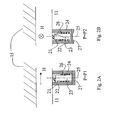
- Figures 2A and 2B show in greater detail the magnetic field source 13 associated to the tyre 11.
- Figure 2A shows the magnetic field source 13 in a first operating configuration relating to a value of pressure P equal to P1
- Figure 2B shows the magnetic field source 13 in a second operating configuration relating to a value of pressure P equal to P2, where P2 is greater than P1.
- Said magnetic field source 13 comprises a permanent magnetic element 21, which generates a magnetic field H with constant modulus and direction.
- Said permanent magnetic element 21, however, is advantageously associated to a rotating element 22, which rotates according to a revolution motion along an axis 25, radial relative to the circumference defined by the tyre 11.
- the rotating element 22 comprises a threaded bar 23, in practice a screw element, positioned along the axis 25 within a coaxial container cylinder 24, able to limit the vibrations produced by the motion of the tyre 11.
- the bar 23 is preferably fastened to a bottom 27 of the cylinder 24 only by means of its own distal end relative to the surface of the tyre 11, in such a way that it follows the axial displacements of said bottom 27, and therefore it is otherwise free to rotate within said cylinder 24 following a thread.
- the permanent magnet 21 On the free end, and thus the proximal one relative to the surface of the tyre 11, of said bar 23 is positioned the permanent magnet 21, which, as shown in Figure 2A , has its own two poles, and hence the associated magnetic field H, arranged according to a direction that is substantially tangential to the surface of the tyre 11.
- the position of the permanent magnet 21 determines a magnetic field H that is tangential and aligned along the direction of rotation of the tyre 11.
- the magnetic field source 13 is subjected to a pressure P2 higher than the pressure P1.
- the bottom 27 of the cylinder 24, which is made of resilient material, by virtue of the pressure rise is deformed, imparting a force along the axis 25 by effect of the thread 26.
- the permanent magnet 21 is rotated by substantially 90° and determines a magnetisation in substantially perpendicular direction to the direction of rotation of the tyre 11.
- bottom 27 could alternatively be formed by means of a piston.
- a spring is provided to return the bar 23 to the original resting position when pressure ceases.
- the pressure measurement therefore, derives from the resultant of the forces of pressure, elastic decompression of the spring and centrifugal forces of the massive movable parts.
- Lubricants can be used to minimise friction between threaded bar 23 and thread 26.
- the magnetic field sensor 14 indirectly measures the pressure P of the tyre 11, directly measuring the direction of the magnetic field H determined by the magnetisation of the permanent magnet 21 positioned on the rotating element 22.
- the magnetic field sensor 14 which can be for instance a spin valve sensor, sensitive to switches in magnetic field direction, is able to perceive the variation in the direction of the magnetic field H, so it can detect the pressure rise.
- appropriate circuits and micro-controllers in the electronic unit can be employed to measure the number of rotations of the permanent magnet 21 which take place over time, for instance by means of a simple counter, and hence determine the pressure of the tyre 17.
- the permanent magnet 21 can be obtained by means of bulk magnetic materials or hard ferromagnetic thin films plated by the corresponding thin film plating techniques such as sputtering or electroplating.
- the permanent magnet 21 can comprise a single film or a stack of multiple films, as well as composite materials constituted by ferromagnetic particles, having variable size (from nanometres to millimetres) and shapes, incorporated and magnetised in a polymeric matrix. Particles can be synthesised on site or off-site in the polymer.
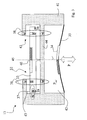
- Figure 3 shows a sensor device according to the invention, in which the magnetic field source 13 comprises a rotating element 32 including a rotating disk 33, which is suspended by magnetic levitation in a container 41 made of non-magnetic material, and set in rotation by a permanent magnet 34, which is associated to a deformable elastic membrane 35.
- the container 41 superiorly comprises a housing 43 for the disk 33 and inferiorly defines a chamber 42, closed inferiorly by the membrane 35.
- the chamber 42 and the housing 43 are separated by a wall 44.
- the pressure P external to the chamber 42, acts on the membrane 35, moving in particular, in the direction of an axis 45 perpendicular to the surface of the disk 33, the centre of said membrane 35 whereon is positioned said permanent magnet 34, which comprises sectors with opposite polarity, in such a way as to set in rotation the magnetic disk 33 when it approaches it by effect of the pressure P.
- the rotating disk 33 in turn comprises magnetic sectors 39, positioned on its outermost circumference.
- magnetic suspensions 38 formed by means of appropriate magnets with opposite polarity, which therefore repel each other, positioned in pairs on the disk 33 and on the container 41, to allow the disk 33 to levitate and rotate in the absence of friction.
- the central area of the disk 33 bears a permanently magnetised area 40, which generates the magnetic field H that is measured by the magnetic field sensor 14.
- the magnetic field sensor 14 in this case needs to be sensitive only to variations in the direction of the magnetisation of said permanently magnetised area 40.
- the interior of the chamber 42 may be pressurised to a reference pressure P ref , in such a way that the membrane 35 is deflected only after the pressure P is greater than said reference pressure P ref .
- centrifugal force on the tyre 11 acts in the same direction as the pressure P. Said centrifugal force can therefore manifest itself as an error in the pressure reading and thus needs compensation.
- centrifugal force can be minimised by providing movable parts with defined ratios between mass and dimensions, in particular the membrane 35 and the magnetic disk 33 for this purpose must have a reduced and a large surface.
- the pressure P determines a force which is proportional to the surface, whilst centrifugal force is a function of mass.
- ABS braking control system which for its operation measures the velocity of rotation of the wheel. From said measurement of the velocity of the wheel, therefore, it is possible to calculate centrifugal force and correct, for instance in the electronic unit of the motor vehicle, for each velocity of rotation the pressure measurement obtained.
- FIG 4 shows a schematic view of an additional embodiment of the invention, in which the magnetic field sensor 14 positioned on the fixed part 15 is sensitive solely to the direction of the magnetic field H.
- the magnetic field source 13 in this case comprises a container 51 made of non-magnetic material which defines a single chamber 52 under reference pressure P ref , delimited inferiorly by a resilient membrane 55 and superiorly by a wall 64.
- Said membrane 55 bears a permanent magnet 54 having a direction of magnetisation M that is substantially parallel to the surface of the membrane.
- the pressure P is exerted on the outer surface of said membrane 55, along an axis 65.
- the container 51 in the wall 64 positioned superiorly to the chamber 52 has an anisotropic ferromagnetic layer 53, whose magnetisation, at rest and in the absence of applied pressure is oriented along the axis orthogonal to the direction of magnetisation M of the permanent magnet 54 lying on the membrane 55.
- FIG. 4 shows said operating configuration, in which the field H produced by the anisotropic ferromagnetic layer 53 is parallel to the direction of magnetisation M of the permanent magnet 54, since said permanent magnet 54 has moved closer under the effect of the pressure P.
- a displacement of the permanent magnet 54 along the axis 65 by effect of the pressure P exerted on the membrane 55 determines a rotation of the magnetic field H originated by the anisotropic ferromagnetic layer 53, which can be measured by the magnetic field sensor 14.
- Said rotation of the magnetic field H of the anisotropic ferromagnetic layer 53 is generally not a sudden transition with respect to the change in the distance from the permanent 54; rather, it is usually a continuous function of distance, since the magnetic domains of the anisotropic ferromagnetic layer 53 do not all switch together. It is therefore possible, by measuring the angle of the direction of the magnetic field H, to have a continuous measurement of the distance of the permanent magnet 54 relative to the anisotropic ferromagnetic layer 53, and hence a continuous measurement of the exerted pressure P.
- the anisotropic ferromagnetic layer 53 can be obtained by means of a composite structure of magnetic particles incorporated in a matrix.
- the membrane 55 can be constituted by a composite elastomeric material, in which the oriented magnetic particles incorporated in an elastomer provide the membrane with magnetic properties whilst altering its elastic properties only to a minimal extent.
- the magnetic particles can be created on-site during the formation of the polymer, or incorporated subsequently.
- the elastomer is made reticular in a magnetic field. The magnetic membrane therefore behaves like an elastic permanent magnet.
- the pressure sensing device advantageously allows to correlate the pressure with rotations in the direction of the magnetic field, so that the correct determination of the intensity of said magnetic field to the sensor has less influence, because the transitions determined by the rotating element can be measured.
- the magnetic field source element and, in particular, there may be multiple elements, of the same type or of different types, located on the rotatably moving part.
- the signals measured by one or more sensors on the fixed part which represent a composite information about pressure, can then be conveniently analysed and processed.
- the magnetic field sensor can be obtained with any digital or analogue magnetic field sensor, such as a simple solenoid, or an AMR (Anisotropic Magnetic Resistance), Hall, GMR (Giant Magnetic Resistance), TMR (Tunnel junction Magneto Resistance) sensor.
- AMR Anagonal Magnetic Resistance
- Hall Hall
- GMR Gaant Magnetic Resistance
- TMR Tunneling Magneto Resistance
- a pressure sensor device of the type described above can be used in a variety of applications requiring the measuring of a pressure.
- the pressure sensor may be a part of an appropriate measuring unit, further comprising tyre wear sensors and/or temperature sensors and, possibly, actuators or valves to re-establish tyre pressure, said unit being located directly on the tyre and powered independently through the conversion of vibration energy deriving from the motion of the tyre.
- the senor positioned on the fixed part to detect magnetic field variations in intensity and/or direction of other magnetic field sources under the control of other quantities, such as temperature.
- the proposed device can be applied in all pressure measurements compatible with a magnetic pressure sensing device like the one described herein, which includes at least one magnetic field source element associated to a rotatably moving part and a magnetic field sensing element associated to a fixed part to measure parameters of a magnetic field determined by said magnetic field source element, said parameters of the magnetic field being a function of the pressure of said rotatably moving part, where the magnetic field source element comprises means for rotating the direction of the emitted magnetic field along at least one axis.
Landscapes
- Engineering & Computer Science (AREA)
- Mechanical Engineering (AREA)
- Measuring Fluid Pressure (AREA)
Claims (13)
- Magnetische Druckfühlvorrichtung für drehbewegliche Teile, der Art umfassend mindestens ein Magnetfeld-Quellelement (13), das dem drehbeweglichen Teil (11) zugeordnet ist, und ein Magnetfeld-Fühlelement (14), das einem festen Teil (15) zugeordnet ist, um Parameter eines Magnetfeldes (H) zu messen, das durch das Magnetfeld-Quellelement (13) bestimmt ist, wobei die Parameter des Magnetfeldes (H) eine Funktion des an das drehbewegliche Teil (11) angelegten Drucks (P) sind, wobei das Magnetfeld-Quellelement (13) Mittel (22) zum Drehen der Richtung des Magnetfeldes (H) um mindestens eine Achse (25) herum als Funktion des an das drehbewegliche Teil (11) angelegten Drucks (P) aufweist,
wobei das Magnetfeld-Quellelement (13) mindestens einen ersten Dauermagneten (21; 40; 53) zum Erzeugen des Magnetfeldes (H) umfasst,
wobei die Mittel (22) zum Drehen der Richtung des Magnetfeldes (H) um mindestens eine Achse (25) herum Mittel (26, 27; 35; 55) zum Umwandeln einer Kraft, die durch den entlang der Achse (25; 45; 65) angelegten Druck (P) bestimmt wird, in eine Drehung der Richtung des Magnetfeldes (H) aufweisen, wobei letztere einen zweiten Dauermagneten (34; 54) aufweisen, der Mitteln zum Umwandeln der Kraft in eine Versetzung entlang der zugeordneten Achse (25; 45; 65) zugeordnet ist,
dadurch gekennzeichnet, dass
der erste Dauermagnet (40; 53) zum Erzeugen des Magnetfeldes (H) an einer ortsfesten Position entlang der Achse (45; 65) einem Wandabschnitt (44; 64) einer Kammer (42; 52) zugeordnet ist, die in den Mitteln (35; 55) zum Umwandeln einer durch den Druck (P) bestimmten Kraft definiert ist,
wobei die Mittel zum Umwandeln der Kraft in eine Versetzung entlang der Achse (45; 65) eine elastische Membrane (35; 55) umfassen, die einen Schließbereich der Kammer (42; 52) definiert. - Vorrichtung nach Anspruch 1, dadurch gekennzeichnet, dass der erste Dauermagnet (40) einer frei schwebenden Scheibe (33) zugeordnet ist, die geeignet ist, durch den zweiten Dauermagneten (34) in Drehbewegung versetzt zu werden.
- Vorrichtung nach Anspruch 1, dadurch gekennzeichnet, dass der erste Dauermagnet (53) imstande ist, die Richtung eines Magnetfeldes (H) auszurichten, das zur Richtung einer Magnetisierung (M) des zweiten Dauermagneten (54) als Funktion des Abstandes zwischen dem ersten (53) und zweiten (54) Dauermagneten ausstrahlt.
- Vorrichtung nach einem der vorhergehenden Ansprüche, dadurch gekennzeichnet, dass die Parameter des durch den Magnetfeld-Sensor (14) gemessenen Magnetfeldes (H) die Richtung und/oder Intensität des Magnetfeldes (H) umfassen.
- Vorrichtung nach einem der vorhergehenden Ansprüche, dadurch gekennzeichnet, dass der Magnetfeld-Sensor (14) imstande ist, die Magnetfeld-Parameter zusätzlicher Magnetfeldquellen gemäß einer physikalischen Größe und dem drehbeweglichen Teil zugeordnet variabel zu messen, wobei die physikalische Größe insbesondere eine Temperatur ist.
- Vorrichtung nach einem oder mehreren der vorhergehenden Ansprüche, dadurch gekennzeichnet, dass das bewegliche Teil (11) ein Reifen für ein Motorfahrzeug ist.
- Vorrichtung nach einem oder mehreren der vorhergehenden Ansprüche, dadurch gekennzeichnet, dass sie in einer Messeinheit beinhaltet ist, weiter umfassend Reifenverschleißsensoren und/oder Temperatursensoren und evtl. Stellglieder oder Ventile, um den Druck des Reifens (11) wieder herzustellen, wobei die Einheit direkt auf dem Reifen (11) positioniert ist.
- Vorrichtung nach einem oder mehreren der vorhergehenden Ansprüche, dadurch gekennzeichnet, dass der erste Dauermagnet (21; 40; 53) und/oder zweite Dauermagnet (34; 54) mit losen magnetischen Materialien oder harten ferromagnetischen Dünnfilmen oder Verbundmaterialien gebildet sind, die durch ferromagnetische Teilchen gebildet sind, die in einer Polymermatrix enthalten und magnetisiert sind.
- Vorrichtung nach einem oder mehreren der Ansprüche 1 bis 8, dadurch gekennzeichnet, dass die elastische Membrane (35; 55) teilweise oder vollständig dem zweiten Dauermagneten (34; 54) entspricht.
- Vorrichtung nach einem oder mehreren der Ansprüche 1 bis 9, dadurch gekennzeichnet, dass der erste Dauermagnet (53) eine anisotrope ferromagnetische Schicht aufweist.
- Vorrichtung nach einem oder mehreren der vorhergehenden Ansprüche, dadurch gekennzeichnet, dass der Magnetfeld-Sensor (14) eine Drehventilvorrichtung ist.
- Verfahren für das Messen des Drucks drehbeweglicher Teile unter Verwendung der Vorrichtung nach einem der Ansprüche 1 bis 11,
dadurch gekennzeichnet, dass
es Schwankungen des Drucks (P) mit Richtungsabweichungen des Magnetfeldes (H) verknüpft, das durch das Magnetfeld-Quellelement (13) erzeugt und durch den Magnetfeld-Sensor (14) gemessen wird. - Verfahren nach Anspruch 12, dadurch gekennzeichnet, dass es weiter Schwankungen des Drucks (P) mit Intensitätsschwankungen des Magnetfeldes (H) verknüpft, das durch das Magnetfeld-Quellelement (13) erzeugt und durch den Magnetfeld-Sensor (14) gemessen wird.
Priority Applications (7)
| Application Number | Priority Date | Filing Date | Title |
|---|---|---|---|
| EP04425078A EP1561608B1 (de) | 2004-02-06 | 2004-02-06 | Drucksensor für rotierende Teile and Verfahren zur Druckerkennung hierfür |
| AT04425078T ATE399657T1 (de) | 2004-02-06 | 2004-02-06 | Drucksensor für rotierende teile and verfahren zur druckerkennung hierfür |
| DE602004014710T DE602004014710D1 (de) | 2004-02-06 | 2004-02-06 | Drucksensor für rotierende Teile and Verfahren zur Druckerkennung hierfür |
| US11/049,656 US7446525B2 (en) | 2004-02-06 | 2005-02-04 | Pressure sensing device for rotatably moving parts and pressure detection method therefor |
| CN200910252902A CN101712265A (zh) | 2004-02-06 | 2005-02-05 | 旋转移动件的磁性压力传感装置 |
| CN2005100080488A CN1651882B (zh) | 2004-02-06 | 2005-02-05 | 旋转移动件的压力传感装置及其压力检测方法 |
| US12/145,074 US7583077B2 (en) | 2004-02-06 | 2008-06-24 | Pressure sensing device for rotatably moving parts |
Applications Claiming Priority (1)
| Application Number | Priority Date | Filing Date | Title |
|---|---|---|---|
| EP04425078A EP1561608B1 (de) | 2004-02-06 | 2004-02-06 | Drucksensor für rotierende Teile and Verfahren zur Druckerkennung hierfür |
Publications (2)
| Publication Number | Publication Date |
|---|---|
| EP1561608A1 EP1561608A1 (de) | 2005-08-10 |
| EP1561608B1 true EP1561608B1 (de) | 2008-07-02 |
Family
ID=34673770
Family Applications (1)
| Application Number | Title | Priority Date | Filing Date |
|---|---|---|---|
| EP04425078A Expired - Lifetime EP1561608B1 (de) | 2004-02-06 | 2004-02-06 | Drucksensor für rotierende Teile and Verfahren zur Druckerkennung hierfür |
Country Status (5)
| Country | Link |
|---|---|
| US (2) | US7446525B2 (de) |
| EP (1) | EP1561608B1 (de) |
| CN (2) | CN1651882B (de) |
| AT (1) | ATE399657T1 (de) |
| DE (1) | DE602004014710D1 (de) |
Cited By (2)
| Publication number | Priority date | Publication date | Assignee | Title |
|---|---|---|---|---|
| US7583077B2 (en) | 2004-02-06 | 2009-09-01 | Crf Societa Consortile Per Azioni | Pressure sensing device for rotatably moving parts |
| US10942078B2 (en) | 2019-05-31 | 2021-03-09 | TYCKit GmbH | Measurement of pressure in pressure-filled containers with flexible walls, in particular tires |
Families Citing this family (16)
| Publication number | Priority date | Publication date | Assignee | Title |
|---|---|---|---|---|
| FR2869410B1 (fr) * | 2004-04-26 | 2006-06-16 | Michelin Soc Tech | Compteur de rotations de pneumatique |
| DE602005017900D1 (de) * | 2005-10-10 | 2010-01-07 | Infineon Technologies Sensonor | Niederfrequenzempfänger mit Magnetfelddetektor |
| JP4165589B2 (ja) * | 2006-08-09 | 2008-10-15 | ソニー株式会社 | 検出装置およびその検出方法 |
| US7557175B2 (en) | 2007-05-03 | 2009-07-07 | Sabic Innovative Plastics Ip B.V. | Poly(carbonate-co-urea) copolymers and melt transesterification method of preparing these copolymers |
| JP2009229453A (ja) * | 2008-02-28 | 2009-10-08 | Seiko Epson Corp | 圧力検出装置及び圧力検出方法 |
| DE102009006707A1 (de) | 2009-01-29 | 2010-08-05 | Bayerische Motoren Werke Aktiengesellschaft | Reifen eines Fahrzeugs mit einem Sensorelement |
| TWI510768B (zh) * | 2011-06-21 | 2015-12-01 | Ind Tech Res Inst | 力感測裝置及其力感測系統 |
| US9766142B1 (en) * | 2015-03-20 | 2017-09-19 | Cory S. Hague | Magnetic force sensor systems and methods |
| US10367265B2 (en) * | 2016-08-05 | 2019-07-30 | Qualcomm Incorporated | Magnetic communication method |
| US10052922B2 (en) | 2016-08-24 | 2018-08-21 | Infineon Technologies Ag | Magnetic sensor used for LF communication in TPMS application |
| NL1042415B1 (en) * | 2017-06-02 | 2018-12-11 | Idbike B V | Displacement measuring device |
| CN108422817B (zh) * | 2018-03-29 | 2023-10-27 | 南京矽力微电子技术有限公司 | 状态控制方法、轮胎压力监测装置和系统 |
| EP3583892A1 (de) * | 2018-06-20 | 2019-12-25 | Koninklijke Philips N.V. | Druckerfassungseinheit, system und verfahren zur ferndruckerfassung |
| CN109186818B (zh) * | 2018-07-23 | 2020-11-27 | 天津大学 | 一种用于压力容器的非接触、非侵入式压力测量方法 |
| CN111879446B (zh) * | 2020-07-16 | 2022-04-08 | 南昌航空大学 | 一种铁磁构件无方向交流电磁场应力测量传感器 |
| US11920992B2 (en) * | 2021-07-20 | 2024-03-05 | Toyota Research Institute, Inc. | Deformable sensors and methods using magnetic repulsion for modifying run-time membrane stiffness |
Family Cites Families (10)
| Publication number | Priority date | Publication date | Assignee | Title |
|---|---|---|---|---|
| DE3242291A1 (de) * | 1982-11-16 | 1984-05-17 | Moto Meter Ag, 7250 Leonberg | Vorrichtung zum messen des reifendrucks in luftreifen von fahrzeugen waehrend der fahrt |
| JPS59216453A (ja) * | 1983-05-20 | 1984-12-06 | Hitachi Metals Ltd | 円筒状永久磁石の製造方法 |
| US4570152A (en) * | 1984-04-23 | 1986-02-11 | Hyperion Corporation | Magnetic tire monitor system |
| FR2622289B1 (fr) | 1987-10-22 | 1990-06-08 | Schrader | Dispositif de surveillance de la pression regnant dans une enceinte close mobile cycliquement et application dans un avertisseur de sous-gonflage de pneumatique |
| US5587698A (en) * | 1992-02-05 | 1996-12-24 | Genna; Robert A. | Automatic tire pressure control system for a vehicle |
| DE4425398A1 (de) * | 1993-07-22 | 1995-01-26 | Nippon Denso Co | Druckerfassungsgerät |
| CA2168940C (en) * | 1995-02-08 | 2007-05-01 | Kenji Furuichi | Tire pressure detector |
| US6906511B2 (en) * | 2001-05-08 | 2005-06-14 | Analog Devices, Inc. | Magnetic position detection for micro machined optical element |
| US6854335B1 (en) * | 2003-12-12 | 2005-02-15 | Mlho, Inc. | Magnetically coupled tire pressure sensing system |
| DE602004014710D1 (de) | 2004-02-06 | 2008-08-14 | Fiat Ricerche | Drucksensor für rotierende Teile and Verfahren zur Druckerkennung hierfür |
-
2004
- 2004-02-06 DE DE602004014710T patent/DE602004014710D1/de not_active Expired - Lifetime
- 2004-02-06 AT AT04425078T patent/ATE399657T1/de not_active IP Right Cessation
- 2004-02-06 EP EP04425078A patent/EP1561608B1/de not_active Expired - Lifetime
-
2005
- 2005-02-04 US US11/049,656 patent/US7446525B2/en not_active Expired - Fee Related
- 2005-02-05 CN CN2005100080488A patent/CN1651882B/zh not_active Expired - Fee Related
- 2005-02-05 CN CN200910252902A patent/CN101712265A/zh active Pending
-
2008
- 2008-06-24 US US12/145,074 patent/US7583077B2/en not_active Expired - Fee Related
Cited By (2)
| Publication number | Priority date | Publication date | Assignee | Title |
|---|---|---|---|---|
| US7583077B2 (en) | 2004-02-06 | 2009-09-01 | Crf Societa Consortile Per Azioni | Pressure sensing device for rotatably moving parts |
| US10942078B2 (en) | 2019-05-31 | 2021-03-09 | TYCKit GmbH | Measurement of pressure in pressure-filled containers with flexible walls, in particular tires |
Also Published As
| Publication number | Publication date |
|---|---|
| EP1561608A1 (de) | 2005-08-10 |
| US7583077B2 (en) | 2009-09-01 |
| ATE399657T1 (de) | 2008-07-15 |
| US7446525B2 (en) | 2008-11-04 |
| CN101712265A (zh) | 2010-05-26 |
| CN1651882A (zh) | 2005-08-10 |
| CN1651882B (zh) | 2010-06-23 |
| DE602004014710D1 (de) | 2008-08-14 |
| US20080258718A1 (en) | 2008-10-23 |
| US20050174109A1 (en) | 2005-08-11 |
Similar Documents
| Publication | Publication Date | Title |
|---|---|---|
| US7583077B2 (en) | Pressure sensing device for rotatably moving parts | |
| KR100900365B1 (ko) | 선회 각도 센서를 가진 볼 조인트 | |
| US6498474B1 (en) | Rotational velocity and direction sensing system | |
| CN102686980B (zh) | 用于检测运动元件位移的磁场传感器装置 | |
| US9086301B2 (en) | Non-contact sensor system and method for displacement determination | |
| CN109655632B (zh) | 具有双角度位置传感器的轮毂组件 | |
| US20090284252A1 (en) | Device for measuring the absolute position of at least two members that are movable or rotatable relative to each other | |
| CN118243952A (zh) | 车轮速度检测装置 | |
| US8164326B2 (en) | Non-contact sensor system and method for velocity determination | |
| EP0698781A1 (de) | Vorrichtung zur Feststellung des Winkelstandes eines Fahrzeuglenkrades | |
| US8405386B2 (en) | Non-contact sensor system and method for position determination | |
| CN109649082A (zh) | 具有双角位置传感器的轮毂组件 | |
| US8203331B2 (en) | Non-contact sensor system and method for selection determination | |
| PARTS | III III a IIOI DID IIO III IO 1101 DII lull ID III DII IID II DI IIi | |
| PARTS | 1111111111111111111111111111111111111111111111111111111111111111111111111II OI II | |
| PARTS | III III a IIOI OlD IIO III 100 III DID 110 III 010 1101 II0 II uii IIi | |
| EP1561609B1 (de) | Temperatursensor für rotierende Teile und Verfahren zur Temperaturmessung hierfür | |
| PARTS | 111111111111111111111111111111111111111111111111111111111111111111111II OI II | |
| EP3708465B1 (de) | Fahrzeug mit lenkwinkelsensor | |
| US11300582B2 (en) | Wheel speed detecting device and wheel bearing assembly comprising same | |
| Buzzi et al. | Drucksensor für rotierende Teile and Verfahren zur Druckerkennung hierfür Capteur de pression pour pièces rotatives et méthode de détection de la pression correspondante | |
| JP2001215235A (ja) | 回転検出装置 | |
| KR100803061B1 (ko) | 휠스피드센서 및 그 감지방법 | |
| JP2004237955A (ja) | タイヤ空気圧監視装置 | |
| JPH1038905A (ja) | 回転検出装置およびそれを備えるハブユニット |
Legal Events
| Date | Code | Title | Description |
|---|---|---|---|
| PUAI | Public reference made under article 153(3) epc to a published international application that has entered the european phase |
Free format text: ORIGINAL CODE: 0009012 |
|
| 17P | Request for examination filed |
Effective date: 20041222 |
|
| AK | Designated contracting states |
Kind code of ref document: A1 Designated state(s): AT BE BG CH CY CZ DE DK EE ES FI FR GB GR HU IE IT LI LU MC NL PT RO SE SI SK TR |
|
| AX | Request for extension of the european patent |
Extension state: AL LT LV MK |
|
| AKX | Designation fees paid |
Designated state(s): AT BE BG CH CY CZ DE DK EE ES FI FR GB GR HU IE IT LI LU MC NL PT RO SE SI SK TR |
|
| 17Q | First examination report despatched |
Effective date: 20061123 |
|
| GRAP | Despatch of communication of intention to grant a patent |
Free format text: ORIGINAL CODE: EPIDOSNIGR1 |
|
| GRAS | Grant fee paid |
Free format text: ORIGINAL CODE: EPIDOSNIGR3 |
|
| GRAA | (expected) grant |
Free format text: ORIGINAL CODE: 0009210 |
|
| AK | Designated contracting states |
Kind code of ref document: B1 Designated state(s): AT BE BG CH CY CZ DE DK EE ES FI FR GB GR HU IE IT LI LU MC NL PT RO SE SI SK TR |
|
| REG | Reference to a national code |
Ref country code: GB Ref legal event code: FG4D |
|
| REG | Reference to a national code |
Ref country code: CH Ref legal event code: EP |
|
| REF | Corresponds to: |
Ref document number: 602004014710 Country of ref document: DE Date of ref document: 20080814 Kind code of ref document: P |
|
| REG | Reference to a national code |
Ref country code: IE Ref legal event code: FG4D |
|
| PG25 | Lapsed in a contracting state [announced via postgrant information from national office to epo] |
Ref country code: SI Free format text: LAPSE BECAUSE OF FAILURE TO SUBMIT A TRANSLATION OF THE DESCRIPTION OR TO PAY THE FEE WITHIN THE PRESCRIBED TIME-LIMIT Effective date: 20080702 |
|
| PG25 | Lapsed in a contracting state [announced via postgrant information from national office to epo] |
Ref country code: NL Free format text: LAPSE BECAUSE OF FAILURE TO SUBMIT A TRANSLATION OF THE DESCRIPTION OR TO PAY THE FEE WITHIN THE PRESCRIBED TIME-LIMIT Effective date: 20080702 |
|
| NLV1 | Nl: lapsed or annulled due to failure to fulfill the requirements of art. 29p and 29m of the patents act | ||
| PG25 | Lapsed in a contracting state [announced via postgrant information from national office to epo] |
Ref country code: ES Free format text: LAPSE BECAUSE OF FAILURE TO SUBMIT A TRANSLATION OF THE DESCRIPTION OR TO PAY THE FEE WITHIN THE PRESCRIBED TIME-LIMIT Effective date: 20081013 Ref country code: PT Free format text: LAPSE BECAUSE OF FAILURE TO SUBMIT A TRANSLATION OF THE DESCRIPTION OR TO PAY THE FEE WITHIN THE PRESCRIBED TIME-LIMIT Effective date: 20081202 |
|
| PG25 | Lapsed in a contracting state [announced via postgrant information from national office to epo] |
Ref country code: BG Free format text: LAPSE BECAUSE OF FAILURE TO SUBMIT A TRANSLATION OF THE DESCRIPTION OR TO PAY THE FEE WITHIN THE PRESCRIBED TIME-LIMIT Effective date: 20081002 Ref country code: FI Free format text: LAPSE BECAUSE OF FAILURE TO SUBMIT A TRANSLATION OF THE DESCRIPTION OR TO PAY THE FEE WITHIN THE PRESCRIBED TIME-LIMIT Effective date: 20080702 Ref country code: AT Free format text: LAPSE BECAUSE OF FAILURE TO SUBMIT A TRANSLATION OF THE DESCRIPTION OR TO PAY THE FEE WITHIN THE PRESCRIBED TIME-LIMIT Effective date: 20080702 |
|
| PG25 | Lapsed in a contracting state [announced via postgrant information from national office to epo] |
Ref country code: BE Free format text: LAPSE BECAUSE OF FAILURE TO SUBMIT A TRANSLATION OF THE DESCRIPTION OR TO PAY THE FEE WITHIN THE PRESCRIBED TIME-LIMIT Effective date: 20080702 |
|
| PG25 | Lapsed in a contracting state [announced via postgrant information from national office to epo] |
Ref country code: DK Free format text: LAPSE BECAUSE OF FAILURE TO SUBMIT A TRANSLATION OF THE DESCRIPTION OR TO PAY THE FEE WITHIN THE PRESCRIBED TIME-LIMIT Effective date: 20080702 Ref country code: EE Free format text: LAPSE BECAUSE OF FAILURE TO SUBMIT A TRANSLATION OF THE DESCRIPTION OR TO PAY THE FEE WITHIN THE PRESCRIBED TIME-LIMIT Effective date: 20080702 |
|
| PLBE | No opposition filed within time limit |
Free format text: ORIGINAL CODE: 0009261 |
|
| STAA | Information on the status of an ep patent application or granted ep patent |
Free format text: STATUS: NO OPPOSITION FILED WITHIN TIME LIMIT |
|
| PG25 | Lapsed in a contracting state [announced via postgrant information from national office to epo] |
Ref country code: CZ Free format text: LAPSE BECAUSE OF FAILURE TO SUBMIT A TRANSLATION OF THE DESCRIPTION OR TO PAY THE FEE WITHIN THE PRESCRIBED TIME-LIMIT Effective date: 20080702 Ref country code: SK Free format text: LAPSE BECAUSE OF FAILURE TO SUBMIT A TRANSLATION OF THE DESCRIPTION OR TO PAY THE FEE WITHIN THE PRESCRIBED TIME-LIMIT Effective date: 20080702 Ref country code: RO Free format text: LAPSE BECAUSE OF FAILURE TO SUBMIT A TRANSLATION OF THE DESCRIPTION OR TO PAY THE FEE WITHIN THE PRESCRIBED TIME-LIMIT Effective date: 20080702 |
|
| 26N | No opposition filed |
Effective date: 20090403 |
|
| PG25 | Lapsed in a contracting state [announced via postgrant information from national office to epo] |
Ref country code: MC Free format text: LAPSE BECAUSE OF NON-PAYMENT OF DUE FEES Effective date: 20090228 |
|
| REG | Reference to a national code |
Ref country code: CH Ref legal event code: PL |
|
| GBPC | Gb: european patent ceased through non-payment of renewal fee |
Effective date: 20090206 |
|
| PG25 | Lapsed in a contracting state [announced via postgrant information from national office to epo] |
Ref country code: LI Free format text: LAPSE BECAUSE OF NON-PAYMENT OF DUE FEES Effective date: 20090228 Ref country code: CH Free format text: LAPSE BECAUSE OF NON-PAYMENT OF DUE FEES Effective date: 20090228 |
|
| REG | Reference to a national code |
Ref country code: IE Ref legal event code: MM4A |
|
| PG25 | Lapsed in a contracting state [announced via postgrant information from national office to epo] |
Ref country code: IE Free format text: LAPSE BECAUSE OF NON-PAYMENT OF DUE FEES Effective date: 20090206 Ref country code: SE Free format text: LAPSE BECAUSE OF FAILURE TO SUBMIT A TRANSLATION OF THE DESCRIPTION OR TO PAY THE FEE WITHIN THE PRESCRIBED TIME-LIMIT Effective date: 20081002 |
|
| PG25 | Lapsed in a contracting state [announced via postgrant information from national office to epo] |
Ref country code: GB Free format text: LAPSE BECAUSE OF NON-PAYMENT OF DUE FEES Effective date: 20090206 |
|
| PG25 | Lapsed in a contracting state [announced via postgrant information from national office to epo] |
Ref country code: GR Free format text: LAPSE BECAUSE OF FAILURE TO SUBMIT A TRANSLATION OF THE DESCRIPTION OR TO PAY THE FEE WITHIN THE PRESCRIBED TIME-LIMIT Effective date: 20081003 |
|
| PG25 | Lapsed in a contracting state [announced via postgrant information from national office to epo] |
Ref country code: LU Free format text: LAPSE BECAUSE OF NON-PAYMENT OF DUE FEES Effective date: 20090206 |
|
| PGFP | Annual fee paid to national office [announced via postgrant information from national office to epo] |
Ref country code: DE Payment date: 20110208 Year of fee payment: 8 Ref country code: FR Payment date: 20110218 Year of fee payment: 8 |
|
| PG25 | Lapsed in a contracting state [announced via postgrant information from national office to epo] |
Ref country code: HU Free format text: LAPSE BECAUSE OF FAILURE TO SUBMIT A TRANSLATION OF THE DESCRIPTION OR TO PAY THE FEE WITHIN THE PRESCRIBED TIME-LIMIT Effective date: 20090103 |
|
| PG25 | Lapsed in a contracting state [announced via postgrant information from national office to epo] |
Ref country code: TR Free format text: LAPSE BECAUSE OF FAILURE TO SUBMIT A TRANSLATION OF THE DESCRIPTION OR TO PAY THE FEE WITHIN THE PRESCRIBED TIME-LIMIT Effective date: 20080702 |
|
| PG25 | Lapsed in a contracting state [announced via postgrant information from national office to epo] |
Ref country code: CY Free format text: LAPSE BECAUSE OF FAILURE TO SUBMIT A TRANSLATION OF THE DESCRIPTION OR TO PAY THE FEE WITHIN THE PRESCRIBED TIME-LIMIT Effective date: 20080702 |
|
| REG | Reference to a national code |
Ref country code: FR Ref legal event code: ST Effective date: 20121031 |
|
| REG | Reference to a national code |
Ref country code: DE Ref legal event code: R119 Ref document number: 602004014710 Country of ref document: DE Effective date: 20120901 |
|
| PG25 | Lapsed in a contracting state [announced via postgrant information from national office to epo] |
Ref country code: FR Free format text: LAPSE BECAUSE OF NON-PAYMENT OF DUE FEES Effective date: 20120229 |
|
| PG25 | Lapsed in a contracting state [announced via postgrant information from national office to epo] |
Ref country code: DE Free format text: LAPSE BECAUSE OF NON-PAYMENT OF DUE FEES Effective date: 20120901 |
|
| PGFP | Annual fee paid to national office [announced via postgrant information from national office to epo] |
Ref country code: IT Payment date: 20140210 Year of fee payment: 11 |
|
| PG25 | Lapsed in a contracting state [announced via postgrant information from national office to epo] |
Ref country code: IT Free format text: LAPSE BECAUSE OF NON-PAYMENT OF DUE FEES Effective date: 20150206 |