EP1561984A1 - Anordnung zur Verbindung von Durchströmungsvorrichtungen - Google Patents
Anordnung zur Verbindung von Durchströmungsvorrichtungen Download PDFInfo
- Publication number
- EP1561984A1 EP1561984A1 EP04002802A EP04002802A EP1561984A1 EP 1561984 A1 EP1561984 A1 EP 1561984A1 EP 04002802 A EP04002802 A EP 04002802A EP 04002802 A EP04002802 A EP 04002802A EP 1561984 A1 EP1561984 A1 EP 1561984A1
- Authority
- EP
- European Patent Office
- Prior art keywords
- arrangement according
- connection
- flow
- sealing element
- wall
- Prior art date
- Legal status (The legal status is an assumption and is not a legal conclusion. Google has not performed a legal analysis and makes no representation as to the accuracy of the status listed.)
- Granted
Links
- 238000007789 sealing Methods 0.000 claims abstract description 29
- 239000004033 plastic Substances 0.000 claims description 5
- 239000013013 elastic material Substances 0.000 claims description 3
- 239000007788 liquid Substances 0.000 abstract description 3
- 239000012530 fluid Substances 0.000 description 23
- 238000004519 manufacturing process Methods 0.000 description 5
- 238000004220 aggregation Methods 0.000 description 2
- 230000002776 aggregation Effects 0.000 description 2
- 239000002826 coolant Substances 0.000 description 2
- 230000000694 effects Effects 0.000 description 2
- 230000000295 complement effect Effects 0.000 description 1
- 150000001875 compounds Chemical class 0.000 description 1
- 230000001419 dependent effect Effects 0.000 description 1
- 238000009826 distribution Methods 0.000 description 1
- 238000005516 engineering process Methods 0.000 description 1
- 238000002347 injection Methods 0.000 description 1
- 239000007924 injection Substances 0.000 description 1
- 238000001746 injection moulding Methods 0.000 description 1
- 238000009434 installation Methods 0.000 description 1
- 238000005058 metal casting Methods 0.000 description 1
- 239000000203 mixture Substances 0.000 description 1
- 125000006850 spacer group Chemical group 0.000 description 1
- 239000013589 supplement Substances 0.000 description 1
- 238000009827 uniform distribution Methods 0.000 description 1
Images
Classifications
-
- F—MECHANICAL ENGINEERING; LIGHTING; HEATING; WEAPONS; BLASTING
- F16—ENGINEERING ELEMENTS AND UNITS; GENERAL MEASURES FOR PRODUCING AND MAINTAINING EFFECTIVE FUNCTIONING OF MACHINES OR INSTALLATIONS; THERMAL INSULATION IN GENERAL
- F16L—PIPES; JOINTS OR FITTINGS FOR PIPES; SUPPORTS FOR PIPES, CABLES OR PROTECTIVE TUBING; MEANS FOR THERMAL INSULATION IN GENERAL
- F16L41/00—Branching pipes; Joining pipes to walls
- F16L41/02—Branch units, e.g. made in one piece, welded, riveted
- F16L41/021—T- or cross-pieces
-
- F—MECHANICAL ENGINEERING; LIGHTING; HEATING; WEAPONS; BLASTING
- F16—ENGINEERING ELEMENTS AND UNITS; GENERAL MEASURES FOR PRODUCING AND MAINTAINING EFFECTIVE FUNCTIONING OF MACHINES OR INSTALLATIONS; THERMAL INSULATION IN GENERAL
- F16L—PIPES; JOINTS OR FITTINGS FOR PIPES; SUPPORTS FOR PIPES, CABLES OR PROTECTIVE TUBING; MEANS FOR THERMAL INSULATION IN GENERAL
- F16L41/00—Branching pipes; Joining pipes to walls
- F16L41/02—Branch units, e.g. made in one piece, welded, riveted
- F16L41/023—Y- pieces
-
- F—MECHANICAL ENGINEERING; LIGHTING; HEATING; WEAPONS; BLASTING
- F28—HEAT EXCHANGE IN GENERAL
- F28F—DETAILS OF HEAT-EXCHANGE AND HEAT-TRANSFER APPARATUS, OF GENERAL APPLICATION
- F28F9/00—Casings; Header boxes; Auxiliary supports for elements; Auxiliary members within casings
- F28F9/02—Header boxes; End plates
- F28F9/0246—Arrangements for connecting header boxes with flow lines
-
- F—MECHANICAL ENGINEERING; LIGHTING; HEATING; WEAPONS; BLASTING
- F28—HEAT EXCHANGE IN GENERAL
- F28F—DETAILS OF HEAT-EXCHANGE AND HEAT-TRANSFER APPARATUS, OF GENERAL APPLICATION
- F28F9/00—Casings; Header boxes; Auxiliary supports for elements; Auxiliary members within casings
- F28F9/26—Arrangements for connecting different sections of heat-exchange elements, e.g. of radiators
- F28F9/262—Arrangements for connecting different sections of heat-exchange elements, e.g. of radiators for radiators
-
- F—MECHANICAL ENGINEERING; LIGHTING; HEATING; WEAPONS; BLASTING
- F28—HEAT EXCHANGE IN GENERAL
- F28D—HEAT-EXCHANGE APPARATUS, NOT PROVIDED FOR IN ANOTHER SUBCLASS, IN WHICH THE HEAT-EXCHANGE MEDIA DO NOT COME INTO DIRECT CONTACT
- F28D21/00—Heat-exchange apparatus not covered by any of the groups F28D1/00 - F28D20/00
- F28D2021/0019—Other heat exchangers for particular applications; Heat exchange systems not otherwise provided for
- F28D2021/008—Other heat exchangers for particular applications; Heat exchange systems not otherwise provided for for vehicles
- F28D2021/0082—Charged air coolers
-
- F—MECHANICAL ENGINEERING; LIGHTING; HEATING; WEAPONS; BLASTING
- F28—HEAT EXCHANGE IN GENERAL
- F28F—DETAILS OF HEAT-EXCHANGE AND HEAT-TRANSFER APPARATUS, OF GENERAL APPLICATION
- F28F9/00—Casings; Header boxes; Auxiliary supports for elements; Auxiliary members within casings
- F28F9/02—Header boxes; End plates
- F28F2009/0285—Other particular headers or end plates
- F28F2009/029—Other particular headers or end plates with increasing or decreasing cross-section, e.g. having conical shape
-
- F—MECHANICAL ENGINEERING; LIGHTING; HEATING; WEAPONS; BLASTING
- F28—HEAT EXCHANGE IN GENERAL
- F28F—DETAILS OF HEAT-EXCHANGE AND HEAT-TRANSFER APPARATUS, OF GENERAL APPLICATION
- F28F2230/00—Sealing means
Definitions
- the invention relates to an arrangement for connecting a first flow device with a first flow channel, a first wall and a first connection region having at least two second ones Flow devices each having a second flow channel, a second wall and a second connection area.
- a known intermediate piece has one each Connection for the first and each second flow device, wherein all connections communicate with each other so that a fluid from the first flow device to the second flow devices distributable or from the second flow devices can be collected on the first flow device.
- the flow devices be this in a known manner to the respective Connections of the intermediate piece connected.
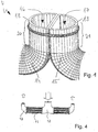
- An example of an intermediate piece is the inflow box 12 of FIG. 4 illustrated double heat exchanger.
- An indicated by a big arrow Fluid is by means of the inflow 12 to two individual heat exchanger 11 distributed, flows through this from the center of the heat exchanger assembly to the outside, are collected in collection boxes 13 and leave the arrangement in the direction of the small arrows.
- the inflow 12 is often a costly for reasons of strength Metal casting, which is welded to the heat exchangers 11. Out Cost reasons, such heat exchanger arrangements are usually used only for small batches. Will the central inflow as cheaper Plastic injection molded part is made with manufacturing technology Problems to be expected, since the known manufacturing facilities for caulking of inflow 12 and several, in particular opposite Heat exchangers 11 are not designed.
- Such an arrangement may be used to distribute a fluid from the first Flow device to the second flow devices or a collection of fluid from the second flow devices on the first flow device.
- the arrangement according to the invention is particularly suitable for liquid and / or gaseous fluids, but excludes the use of fluids in other states of aggregation such as the supercritical not out.
- the fluid is, for example, an element, a compound or a mixture from any number of elements and / or connections, in particular exist in different states of aggregation.
- the first flow device has a first flow channel for the fluid and a first wall and a first connection area for connection to the second flow devices.
- each second flow device has a second flow channel for the fluid and a second wall and a second Connection area for a connection with at least the first flow device on.
- the object of the invention is advantageously achieved in that the second Connection areas collectively in the first connection area receivable are, wherein a flow connection between the first flow channel and the second flow channels is formed. Across from known connection arrangements is thereby under some circumstances Saved component and reduced a manufacturing and / or assembly costs.
- the first and / or at least one second flow device formed as a tube or hose.
- the first and / or at least a second flow device at least partially made of plastic.
- the first connection area a circular, elliptical, oval or rectangular cross-sectional area.
- This may be a simple design.
- a circular cross-sectional area of the first connection portion is a circular segmental cross-sectional area, such as a half or Quarter-circular cross-sectional area, at least a second connection area possibly advantageous.
- each second connection region has a circular segment-shaped cross-sectional area, on.
- all second connection areas an equal cross-sectional area and complement each other to a circular cross-sectional area.
- the cross sections are at least two second connection areas substantially the same size. Thereby Under certain circumstances, a uniform distribution of the fluid to the second Flow devices supported.
- the cross sections are at least two second connection areas substantially the same.
- two second flow devices are symmetrical, preferably mirror image, each formed and / or arranged and / or flow through.
- interchangeability is possibly second Flow devices allows, so that in particular a versatile Applicability of the arrangement according to the invention is achieved.
- the invention is between the first wall and at least a second wall disposed a first sealing element.
- a second sealing element is between two second walls arranged a second sealing element. This also may result a leakage of the flowing through the flow devices Fluid from the inventive arrangement prevents or at least slowed down.
- At least one first sealing element formed integrally with at least one second sealing element.
- At least one sealing element an elastic material, such as rubber.
- an elastic material such as rubber.
- a sealing element substantially entirely of one or more elastic Materials. This will eventually a sealing effect improved.
- the invention is in the first and / or at least a second wall provided a receptacle for a sealing element. As a result, an assembly of the sealing element is possibly facilitated.
- At least one receptacle for a Sealing formed as at least partially circumferential recess.
- the sealing element is particularly easy to insert under certain circumstances and mountable with it.
- a connection line is thereby possibly on easy to connect to a heat exchanger.
- the connection line in particular in this embodiment a supply line and / or a drain line of a heat exchanger.
- a heat exchanger comprises a Anström channel and a discharge channel for a fluid to be cooled and a Pipe network.
- the heat exchanger arrangement is for example a mirror image of a plane, if necessary formed with respect to a central longitudinal plane of a motor vehicle.
- Such a split design may allow a space-saving installation, especially in the vicinity of another Heat exchanger, such as a motor vehicle coolant radiator.
- Such a heat transfer system is particular for charge air as fluid to be cooled, but also for other fluids, such as Coolant or oil suitable.
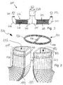
- Fig. 1 is an arrangement 4 for connecting a for a better clarity not shown first flow device with two second flow devices 14 and 15, each formed as a tube are.
- the connection arrangement 4 serves a distribution of a Fluids, in particular a gas or a liquid, from the advantageously designed as a flexible hose first flow device on the tubes 14, 15.
- the tubes 14 and 15 each have a second flow channel 16 and 17 for the fluid and a second wall 18 and 19 and a second Connection area 20 or 21 for connection with each other and with the first flow device on.
- the first connection area of the first tube has a circular cross-sectional area
- the second connecting portions of the tubes 14 and 15 each one Have semicircular cross-sectional area and each other to a circular overall cross-sectional area corresponding to the cross-sectional area of the first Hose complements, supplement.
- To apply the fluid evenly to the two Splitting pipes 14 and 15 are the cross sections of the second connection areas 20 and 21 arranged the same and mirror images of each other and thus flowed through.
- the second connection regions 20 and 21 are the second Walls 18 and 19 to each other, so that the second connection areas together in the first connection area are receivable, wherein a flow connection between a first flow channel in the first tube and the second flow channels 16 and 17 are formed becomes.
- the arrangement shown in Fig. 1 for example in a first connection region of a first flow device inserted or plugged in or such a first connection area is plugged or put on the arrangement.
- FIG. 2 shows a connection arrangement 104 according to the invention for a better clarity before assembly shown.
- Two second pipes 114 and 115 with second flow channels 116 and 117 and second walls 118 and 119 and second connection areas 120 and 121 are for provided a flow through a fluid.
- a first pipe with a first flow channel for the fluid, a first wall and a first connection area to a receptacle of the second connection areas 120 and 121 is not shown for clarity.
- a first sealing element 160 is provided for a seal between the first wall and the second wall 118.
- a first sealing element 180 is provided for one Seal between the first wall and the second wall 119th.
- a second sealing element 170 is provided for a seal between the second walls 118 and 119. This will cause leakage through the flow devices flowing fluid from the connection assembly 104 prevented.
- the first sealing elements 160 and 180 are together with the second Seal member 170 integrally formed, so that a preferably from Rubber existing 8-shaped sealing element 190 is formed.
- the sealing effect of the sealing element 190 is supported by second recordings 122 and 123 in the second walls 118 and 119, respectively.
- the photographs 122 and 123 are formed as circumferential recesses and take both the first sealing elements 160 and 180 and the second Seal element 170 on.
- the sealing element 190 is so easy in the pictures 122 and 123 inserted, so that an assembly effort for the connection arrangement 104 is reduced.
- connection arrangement in three or more second flow devices possible for which the corresponding second flow channels, for example third circular and the sealing element optionally with three corresponding Openings is formed.
- Fig. 3 shows an arrangement 201 for connecting two heat exchangers 202 and 203 with a connecting line 1204.
- the heat exchanger 202 and 203 each have a flow box 204 and 205 with a therein inflow channel and an outflow box 206 and 207th with an outflow channel therein for a temperature to be tempered, in particular fluid to be cooled and between the boxes 204 and 206th or 205 and 207 arranged tube-rib network 208 and 209 on.
- the Boxes 204, 205, 206 and / or 207 are advantageously made of plastic produced.
- the heat exchanger assembly 201 is mirror-inverted with respect to a plane educated.
- the fluid to be cooled flows in the direction of the arrow 210 through the connecting line 1204, is evenly on the two heat exchanger 202 and 203 and finally leaves the assembly 204 in the direction of the arrows 211 and 212, respectively.
Landscapes
- Engineering & Computer Science (AREA)
- General Engineering & Computer Science (AREA)
- Mechanical Engineering (AREA)
- Physics & Mathematics (AREA)
- Thermal Sciences (AREA)
- Heat-Exchange Devices With Radiators And Conduit Assemblies (AREA)
- Quick-Acting Or Multi-Walled Pipe Joints (AREA)
- Cultivation Receptacles Or Flower-Pots, Or Pots For Seedlings (AREA)
Abstract
Description
- Fig. 1
- eine erfindungsgemäße Verbindungsanordnung,
- Fig. 2
- eine Verbindungsanordnung vor einer Montage und
- Fig. 3, 4
- jeweils eine Verbindungsanordnung mit zwei Wärmeübertragern.
Claims (17)
- Anordnung zur Verbindung einer ersten Durchströmungsvorrichtung mit zumindest zwei zweiten Durchströmungsvorrichtungen, wobei die erste Durchströmungsvorrichtung einen ersten Strömungskanal und eine erste Wandung sowie einen ersten Verbindungsbereich aufweist, und jede zweite Durchströmungsvorrichtung einen zweiten Strömungskanal und eine zweite Wandung sowie einen zweiten Verbindungsbereich aufweist, dadurch gekennzeichnet, daß die zweiten Verbindungsbereiche unter Bildung einer Strömungsverbindung zwischen dem ersten Strömungskanal und den zweiten Strömungskanälen gemeinsam in den ersten Verbindungsbereich aufnehmbar sind.
- Anordnung nach einem der vorhergehenden Ansprüche, dadurch gekennzeichnet, daß die erste und/oder zumindest eine zweite Durchströmungsvorrichtung als Rohr oder als Schlauch ausgebildet ist.
- Anordnung nach einem der vorhergehenden Ansprüche, dadurch gekennzeichnet, daß die erste und/oder zumindest eine zweite Durchströmungsvorrichtung zumindest teilweise aus Kunststoff besteht.
- Anordnung nach einem der vorhergehenden Ansprüche, dadurch gekennzeichnet, daß der erste Verbindungsbereich eine kreis-, ellipsen-, oval- oder rechteckförmige Querschnittsfläche aufweist.
- Anordnung nach einem der vorhergehenden Ansprüche, dadurch gekennzeichnet, daß zumindest ein zweiter Verbindungsbereich eine kreissegmentförmige Querschnittsfläche aufweist.
- Anordnung nach einem der vorhergehenden Ansprüche, dadurch gekennzeichnet, daß die Querschnitte zumindest zweier zweiter Verbindungsbereiche im wesentlichen gleich groß sind.
- Anordnung nach einem der vorhergehenden Ansprüche, dadurch gekennzeichnet, daß die Querschnitte zumindest zweier zweiter Verbindungsbereiche im wesentlichen gleich sind.
- Anordnung nach einem der vorhergehenden Ansprüche, dadurch gekennzeichnet, daß zumindest zwei zweite Durchströmungsvorrichtungen symmetrisch, insbesondere spiegelbildlich, zueinander ausgebildet und/oder angeordnet und/oder durchströmbar sind.
- Anordnung nach einem der vorhergehenden Ansprüche, dadurch gekennzeichnet, daß zwischen der ersten Wandung und zumindest einer zweiten Wandung ein erstes Dichtelement angeordnet ist.
- Anordnung nach einem der vorhergehenden Ansprüche, dadurch gekennzeichnet; daß zwischen zwei zweiten Wandungen ein zweites Dichtelement angeordnet ist.
- Anordnung nach einem der vorhergehenden Ansprüche, dadurch gekennzeichnet, daß zumindest ein erstes Dichtelement mit zumindest einem zweiten Dichtelement einstückig ausgebildet ist.
- Anordnung nach einem der vorhergehenden Ansprüche, dadurch gekennzeichnet, daß zumindest ein Dichtelement ein elastisches Material enthält.
- Anordnung nach einem der vorhergehenden Ansprüche, dadurch gekennzeichnet, daß in der ersten und/oder zumindest einer zweiten Wandung eine Aufnahme für ein Dichtelement vorgesehen ist.
- Anordnung nach einem der vorhergehenden Ansprüche, dadurch gekennzeichnet, daß zumindest eine Aufnahme für ein Dichtelement als zumindest teilweise umlaufende Vertiefung ausgebildet ist.
- Anordnung nach einem der vorhergehenden Ansprüche, dadurch gekennzeichnet, daß zumindest eine zweite Durchströmungsvorrichtung als Wärmeübertrager, insbesondere Ladeluftkühler für ein Kraftfahrzeug, und die erste Durchströmungsvorrichtung als Anschlußleitung ausgebildet ist.
- Anordnung nach einem der vorhergehenden Ansprüche, dadurch gekennzeichnet, daß die Anschlußleitung eine Zulaufleitung, insbesondere eines Wärmeübertragers, ist.
- Anordnung nach einem der vorhergehenden Ansprüche, dadurch gekennzeichnet, daß die Anschlußleitung eine Ablaufleitung, insbesondere eines Wärmeübertragers, ist.
Priority Applications (4)
| Application Number | Priority Date | Filing Date | Title |
|---|---|---|---|
| EP04002802A EP1561984B1 (de) | 2004-02-09 | 2004-02-09 | Anordnung zur Verbindung von Durchströmungsvorrichtungen |
| DE502004006656T DE502004006656D1 (de) | 2004-02-09 | 2004-02-09 | Anordnung zur Verbindung von Durchströmungsvorrichtungen |
| ES04002802T ES2304557T3 (es) | 2004-02-09 | 2004-02-09 | Disposicion para la conexion de dispositivos de circulacion. |
| AT04002802T ATE390592T1 (de) | 2004-02-09 | 2004-02-09 | Anordnung zur verbindung von durchströmungsvorrichtungen |
Applications Claiming Priority (1)
| Application Number | Priority Date | Filing Date | Title |
|---|---|---|---|
| EP04002802A EP1561984B1 (de) | 2004-02-09 | 2004-02-09 | Anordnung zur Verbindung von Durchströmungsvorrichtungen |
Publications (2)
| Publication Number | Publication Date |
|---|---|
| EP1561984A1 true EP1561984A1 (de) | 2005-08-10 |
| EP1561984B1 EP1561984B1 (de) | 2008-03-26 |
Family
ID=34673697
Family Applications (1)
| Application Number | Title | Priority Date | Filing Date |
|---|---|---|---|
| EP04002802A Expired - Lifetime EP1561984B1 (de) | 2004-02-09 | 2004-02-09 | Anordnung zur Verbindung von Durchströmungsvorrichtungen |
Country Status (4)
| Country | Link |
|---|---|
| EP (1) | EP1561984B1 (de) |
| AT (1) | ATE390592T1 (de) |
| DE (1) | DE502004006656D1 (de) |
| ES (1) | ES2304557T3 (de) |
Citations (4)
| Publication number | Priority date | Publication date | Assignee | Title |
|---|---|---|---|---|
| US1801091A (en) * | 1928-05-22 | 1931-04-14 | Krauss Richard | High-pressure water pipe |
| US3336056A (en) * | 1965-03-25 | 1967-08-15 | Gen Motors Corp | Conduit system |
| US3476869A (en) * | 1967-11-21 | 1969-11-04 | Benjamin K Hawkins | Conduit system |
| EP0806598A1 (de) * | 1996-05-08 | 1997-11-12 | Sango Co., Ltd. | Abzweigrohr und Verfahren zu dessen Herstellung |
-
2004
- 2004-02-09 ES ES04002802T patent/ES2304557T3/es not_active Expired - Lifetime
- 2004-02-09 DE DE502004006656T patent/DE502004006656D1/de not_active Expired - Lifetime
- 2004-02-09 AT AT04002802T patent/ATE390592T1/de not_active IP Right Cessation
- 2004-02-09 EP EP04002802A patent/EP1561984B1/de not_active Expired - Lifetime
Patent Citations (4)
| Publication number | Priority date | Publication date | Assignee | Title |
|---|---|---|---|---|
| US1801091A (en) * | 1928-05-22 | 1931-04-14 | Krauss Richard | High-pressure water pipe |
| US3336056A (en) * | 1965-03-25 | 1967-08-15 | Gen Motors Corp | Conduit system |
| US3476869A (en) * | 1967-11-21 | 1969-11-04 | Benjamin K Hawkins | Conduit system |
| EP0806598A1 (de) * | 1996-05-08 | 1997-11-12 | Sango Co., Ltd. | Abzweigrohr und Verfahren zu dessen Herstellung |
Also Published As
| Publication number | Publication date |
|---|---|
| DE502004006656D1 (de) | 2008-05-08 |
| ES2304557T3 (es) | 2008-10-16 |
| ATE390592T1 (de) | 2008-04-15 |
| EP1561984B1 (de) | 2008-03-26 |
Similar Documents
| Publication | Publication Date | Title |
|---|---|---|
| EP0828980B1 (de) | Wärmetauscher | |
| DE19536116B4 (de) | Wärmeübertrager für ein Kraftfahrzeug | |
| DE3319521C2 (de) | ||
| EP3489603B1 (de) | Wärmetauscher | |
| EP2302183A2 (de) | Wärmeüberträger | |
| DE102013020469A1 (de) | Wärmeübertrager und Verfahren zum Herstellen eines Wärmeübertragers | |
| EP2037201A2 (de) | Ladeluftmodul für eine Verbrennungskraftmaschine | |
| EP2297539A2 (de) | Plattenkühler für flüssigkeiten | |
| DE20121112U1 (de) | Sammelkasten für einen Wärmeaustauscher, insbesondere an Kraftfahrzeugen | |
| DE102019127707A1 (de) | Bauteil für eine Extrusionslinie | |
| DE10228247B4 (de) | Luftansaugkanalsystem | |
| EP3011248B1 (de) | Vorrichtung zur einflussnahme auf den abströmbereich einer rohrträgerplatte eines rohrbündel-wärmeaustauschers | |
| DE102019103210A1 (de) | Winkelstück zum fluidkommunizierenden Verbinden von Fluidleitungen eines Fahrzeugs | |
| DE102014112223A1 (de) | Kühleinrichtung | |
| DE102017219433A1 (de) | Wärmeübertrager für einen Verbrennungsmotor | |
| EP3012084B1 (de) | Fitting | |
| DE102009014936A1 (de) | Abwasserrohr mit einer Frischwasserleiteinrichtung sowie Wärmeübertrager | |
| DE102006053702B4 (de) | Wärmetauscher, insbesondere Gaskühler | |
| EP1561984B1 (de) | Anordnung zur Verbindung von Durchströmungsvorrichtungen | |
| EP3822569A1 (de) | Wärmetauscher | |
| EP4089357B1 (de) | Wärmetauscher | |
| DE102004055598B3 (de) | Rohrbündelhochdruckwärmetauscher | |
| DE102005051709A1 (de) | Abgaskühler | |
| DE102023120030A1 (de) | Kugelventil | |
| DE10257363C1 (de) | Formbackenhälfte für eine Vorrichtung zur Erstellung von Querrippenrohren |
Legal Events
| Date | Code | Title | Description |
|---|---|---|---|
| PUAI | Public reference made under article 153(3) epc to a published international application that has entered the european phase |
Free format text: ORIGINAL CODE: 0009012 |
|
| AK | Designated contracting states |
Kind code of ref document: A1 Designated state(s): AT BE BG CH CY CZ DE DK EE ES FI FR GB GR HU IE IT LI LU MC NL PT RO SE SI SK TR |
|
| AX | Request for extension of the european patent |
Extension state: AL LT LV MK |
|
| 17P | Request for examination filed |
Effective date: 20060210 |
|
| AKX | Designation fees paid |
Designated state(s): AT BE BG CH CY CZ DE DK EE ES FI FR GB GR HU IE IT LI LU MC NL PT RO SE SI SK TR |
|
| GRAP | Despatch of communication of intention to grant a patent |
Free format text: ORIGINAL CODE: EPIDOSNIGR1 |
|
| GRAS | Grant fee paid |
Free format text: ORIGINAL CODE: EPIDOSNIGR3 |
|
| GRAA | (expected) grant |
Free format text: ORIGINAL CODE: 0009210 |
|
| AK | Designated contracting states |
Kind code of ref document: B1 Designated state(s): AT BE BG CH CY CZ DE DK EE ES FI FR GB GR HU IE IT LI LU MC NL PT RO SE SI SK TR |
|
| REG | Reference to a national code |
Ref country code: GB Ref legal event code: FG4D Free format text: NOT ENGLISH |
|
| REG | Reference to a national code |
Ref country code: CH Ref legal event code: EP Ref country code: IE Ref legal event code: FG4D Free format text: LANGUAGE OF EP DOCUMENT: GERMAN |
|
| REF | Corresponds to: |
Ref document number: 502004006656 Country of ref document: DE Date of ref document: 20080508 Kind code of ref document: P |
|
| REG | Reference to a national code |
Ref country code: SE Ref legal event code: TRGR |
|
| PG25 | Lapsed in a contracting state [announced via postgrant information from national office to epo] |
Ref country code: FI Free format text: LAPSE BECAUSE OF FAILURE TO SUBMIT A TRANSLATION OF THE DESCRIPTION OR TO PAY THE FEE WITHIN THE PRESCRIBED TIME-LIMIT Effective date: 20080326 |
|
| NLV1 | Nl: lapsed or annulled due to failure to fulfill the requirements of art. 29p and 29m of the patents act | ||
| PG25 | Lapsed in a contracting state [announced via postgrant information from national office to epo] |
Ref country code: SI Free format text: LAPSE BECAUSE OF FAILURE TO SUBMIT A TRANSLATION OF THE DESCRIPTION OR TO PAY THE FEE WITHIN THE PRESCRIBED TIME-LIMIT Effective date: 20080326 |
|
| REG | Reference to a national code |
Ref country code: ES Ref legal event code: FG2A Ref document number: 2304557 Country of ref document: ES Kind code of ref document: T3 |
|
| REG | Reference to a national code |
Ref country code: IE Ref legal event code: FD4D |
|
| PG25 | Lapsed in a contracting state [announced via postgrant information from national office to epo] |
Ref country code: PT Free format text: LAPSE BECAUSE OF FAILURE TO SUBMIT A TRANSLATION OF THE DESCRIPTION OR TO PAY THE FEE WITHIN THE PRESCRIBED TIME-LIMIT Effective date: 20080901 Ref country code: SK Free format text: LAPSE BECAUSE OF FAILURE TO SUBMIT A TRANSLATION OF THE DESCRIPTION OR TO PAY THE FEE WITHIN THE PRESCRIBED TIME-LIMIT Effective date: 20080326 |
|
| PG25 | Lapsed in a contracting state [announced via postgrant information from national office to epo] |
Ref country code: RO Free format text: LAPSE BECAUSE OF FAILURE TO SUBMIT A TRANSLATION OF THE DESCRIPTION OR TO PAY THE FEE WITHIN THE PRESCRIBED TIME-LIMIT Effective date: 20080326 Ref country code: NL Free format text: LAPSE BECAUSE OF FAILURE TO SUBMIT A TRANSLATION OF THE DESCRIPTION OR TO PAY THE FEE WITHIN THE PRESCRIBED TIME-LIMIT Effective date: 20080326 |
|
| ET | Fr: translation filed | ||
| PG25 | Lapsed in a contracting state [announced via postgrant information from national office to epo] |
Ref country code: DK Free format text: LAPSE BECAUSE OF FAILURE TO SUBMIT A TRANSLATION OF THE DESCRIPTION OR TO PAY THE FEE WITHIN THE PRESCRIBED TIME-LIMIT Effective date: 20080326 Ref country code: IE Free format text: LAPSE BECAUSE OF FAILURE TO SUBMIT A TRANSLATION OF THE DESCRIPTION OR TO PAY THE FEE WITHIN THE PRESCRIBED TIME-LIMIT Effective date: 20080326 |
|
| PLBE | No opposition filed within time limit |
Free format text: ORIGINAL CODE: 0009261 |
|
| STAA | Information on the status of an ep patent application or granted ep patent |
Free format text: STATUS: NO OPPOSITION FILED WITHIN TIME LIMIT |
|
| 26N | No opposition filed |
Effective date: 20081230 |
|
| PG25 | Lapsed in a contracting state [announced via postgrant information from national office to epo] |
Ref country code: EE Free format text: LAPSE BECAUSE OF FAILURE TO SUBMIT A TRANSLATION OF THE DESCRIPTION OR TO PAY THE FEE WITHIN THE PRESCRIBED TIME-LIMIT Effective date: 20080326 Ref country code: BG Free format text: LAPSE BECAUSE OF FAILURE TO SUBMIT A TRANSLATION OF THE DESCRIPTION OR TO PAY THE FEE WITHIN THE PRESCRIBED TIME-LIMIT Effective date: 20080626 |
|
| BERE | Be: lapsed |
Owner name: FRAPE BEHR S.A. Effective date: 20090228 |
|
| PG25 | Lapsed in a contracting state [announced via postgrant information from national office to epo] |
Ref country code: IT Free format text: LAPSE BECAUSE OF FAILURE TO SUBMIT A TRANSLATION OF THE DESCRIPTION OR TO PAY THE FEE WITHIN THE PRESCRIBED TIME-LIMIT Effective date: 20080326 |
|
| PG25 | Lapsed in a contracting state [announced via postgrant information from national office to epo] |
Ref country code: MC Free format text: LAPSE BECAUSE OF NON-PAYMENT OF DUE FEES Effective date: 20090228 Ref country code: CY Free format text: LAPSE BECAUSE OF FAILURE TO SUBMIT A TRANSLATION OF THE DESCRIPTION OR TO PAY THE FEE WITHIN THE PRESCRIBED TIME-LIMIT Effective date: 20080326 |
|
| REG | Reference to a national code |
Ref country code: CH Ref legal event code: PL |
|
| EUG | Se: european patent has lapsed | ||
| GBPC | Gb: european patent ceased through non-payment of renewal fee |
Effective date: 20090209 |
|
| PG25 | Lapsed in a contracting state [announced via postgrant information from national office to epo] |
Ref country code: CZ Free format text: LAPSE BECAUSE OF NON-PAYMENT OF DUE FEES Effective date: 20090209 Ref country code: CH Free format text: LAPSE BECAUSE OF NON-PAYMENT OF DUE FEES Effective date: 20090228 Ref country code: LI Free format text: LAPSE BECAUSE OF NON-PAYMENT OF DUE FEES Effective date: 20090228 |
|
| PG25 | Lapsed in a contracting state [announced via postgrant information from national office to epo] |
Ref country code: BE Free format text: LAPSE BECAUSE OF NON-PAYMENT OF DUE FEES Effective date: 20090228 |
|
| REG | Reference to a national code |
Ref country code: ES Ref legal event code: FD2A Effective date: 20090210 |
|
| PG25 | Lapsed in a contracting state [announced via postgrant information from national office to epo] |
Ref country code: GB Free format text: LAPSE BECAUSE OF NON-PAYMENT OF DUE FEES Effective date: 20090209 |
|
| PG25 | Lapsed in a contracting state [announced via postgrant information from national office to epo] |
Ref country code: AT Free format text: LAPSE BECAUSE OF NON-PAYMENT OF DUE FEES Effective date: 20090209 |
|
| PG25 | Lapsed in a contracting state [announced via postgrant information from national office to epo] |
Ref country code: ES Free format text: LAPSE BECAUSE OF NON-PAYMENT OF DUE FEES Effective date: 20090210 |
|
| PG25 | Lapsed in a contracting state [announced via postgrant information from national office to epo] |
Ref country code: GR Free format text: LAPSE BECAUSE OF FAILURE TO SUBMIT A TRANSLATION OF THE DESCRIPTION OR TO PAY THE FEE WITHIN THE PRESCRIBED TIME-LIMIT Effective date: 20080627 |
|
| PG25 | Lapsed in a contracting state [announced via postgrant information from national office to epo] |
Ref country code: LU Free format text: LAPSE BECAUSE OF NON-PAYMENT OF DUE FEES Effective date: 20090209 |
|
| PG25 | Lapsed in a contracting state [announced via postgrant information from national office to epo] |
Ref country code: SE Free format text: LAPSE BECAUSE OF NON-PAYMENT OF DUE FEES Effective date: 20090210 |
|
| PG25 | Lapsed in a contracting state [announced via postgrant information from national office to epo] |
Ref country code: HU Free format text: LAPSE BECAUSE OF FAILURE TO SUBMIT A TRANSLATION OF THE DESCRIPTION OR TO PAY THE FEE WITHIN THE PRESCRIBED TIME-LIMIT Effective date: 20080927 |
|
| PG25 | Lapsed in a contracting state [announced via postgrant information from national office to epo] |
Ref country code: TR Free format text: LAPSE BECAUSE OF FAILURE TO SUBMIT A TRANSLATION OF THE DESCRIPTION OR TO PAY THE FEE WITHIN THE PRESCRIBED TIME-LIMIT Effective date: 20080326 |
|
| PGFP | Annual fee paid to national office [announced via postgrant information from national office to epo] |
Ref country code: FR Payment date: 20120330 Year of fee payment: 9 |
|
| PGFP | Annual fee paid to national office [announced via postgrant information from national office to epo] |
Ref country code: DE Payment date: 20120411 Year of fee payment: 9 |
|
| REG | Reference to a national code |
Ref country code: FR Ref legal event code: ST Effective date: 20131031 |
|
| REG | Reference to a national code |
Ref country code: DE Ref legal event code: R119 Ref document number: 502004006656 Country of ref document: DE Effective date: 20130903 |
|
| PG25 | Lapsed in a contracting state [announced via postgrant information from national office to epo] |
Ref country code: DE Free format text: LAPSE BECAUSE OF NON-PAYMENT OF DUE FEES Effective date: 20130903 Ref country code: FR Free format text: LAPSE BECAUSE OF NON-PAYMENT OF DUE FEES Effective date: 20130228 |