EP1561999A2 - Dichtungsvorrichtung für Membrangefäss - Google Patents
Dichtungsvorrichtung für Membrangefäss Download PDFInfo
- Publication number
- EP1561999A2 EP1561999A2 EP05002435A EP05002435A EP1561999A2 EP 1561999 A2 EP1561999 A2 EP 1561999A2 EP 05002435 A EP05002435 A EP 05002435A EP 05002435 A EP05002435 A EP 05002435A EP 1561999 A2 EP1561999 A2 EP 1561999A2
- Authority
- EP
- European Patent Office
- Prior art keywords
- liner
- passage fitting
- ring
- outer shell
- holder
- Prior art date
- Legal status (The legal status is an assumption and is not a legal conclusion. Google has not performed a legal analysis and makes no representation as to the accuracy of the status listed.)
- Withdrawn
Links
Images


Classifications
-
- F—MECHANICAL ENGINEERING; LIGHTING; HEATING; WEAPONS; BLASTING
- F24—HEATING; RANGES; VENTILATING
- F24D—DOMESTIC- OR SPACE-HEATING SYSTEMS, e.g. CENTRAL HEATING SYSTEMS; DOMESTIC HOT-WATER SUPPLY SYSTEMS; ELEMENTS OR COMPONENTS THEREFOR
- F24D3/00—Hot-water central heating systems
- F24D3/10—Feed-line arrangements, e.g. providing for heat-accumulator tanks, expansion tanks ; Hydraulic components of a central heating system
- F24D3/1008—Feed-line arrangements, e.g. providing for heat-accumulator tanks, expansion tanks ; Hydraulic components of a central heating system expansion tanks
- F24D3/1016—Tanks having a bladder
-
- F—MECHANICAL ENGINEERING; LIGHTING; HEATING; WEAPONS; BLASTING
- F24—HEATING; RANGES; VENTILATING
- F24D—DOMESTIC- OR SPACE-HEATING SYSTEMS, e.g. CENTRAL HEATING SYSTEMS; DOMESTIC HOT-WATER SUPPLY SYSTEMS; ELEMENTS OR COMPONENTS THEREFOR
- F24D3/00—Hot-water central heating systems
- F24D3/10—Feed-line arrangements, e.g. providing for heat-accumulator tanks, expansion tanks ; Hydraulic components of a central heating system
- F24D3/1008—Feed-line arrangements, e.g. providing for heat-accumulator tanks, expansion tanks ; Hydraulic components of a central heating system expansion tanks
Definitions
- This invention pertains to improvements for diaphragm expansion tanks, and, more particularly, to a mechanism to better seal the bladder of an expansion tank.
- a diaphragm tank 12 for potable water typically has a metal shell 22 and a plastic liner 24 (Figure 1).
- a diaphragm 26 is mounted below the liner 24, defining an air cushion between the shell 22 and the diaphragm 26 and an expandable bladder enclosed by diaphragm 26 and liner 24.
- a gasket 28 is usually mounted around the hole between the shell 22 and the liner 24 to stiffen the metal shell 22 and plastic liner 24 in the area of the hole and to form an airtight seal to block the leakage of air (Figure 2).
- a connector 10 is mounted on diaphragm tank 12 to allow fluid to flow into or out of the tank (Figure 1).
- Connector 10 extends through both the shell 22 and the liner 24.
- a conventional connector includes a passage fitting 14 and an o-ring 16 mounted around the passage fitting 14 ( Figure 2).
- the interior end of the passage fitting 14 is bent into a curled end 18 to retain the o-ring 16 on the passage fitting 14.
- a shoulder 20 abuts the outside of the tank 12, allowing the wall of tank 12 to be clamped between the shoulder 20 and the curled end 18 of the passage fitting 14.
- the connector 10 links the tank to a water flow.
- water flows into the bladder.
- the pressurized air in the tank expands against the bladder, pushing the water out until the air pressure is the same as the water pressure or the tank is empty.
- the invention is a diaphragm tank.
- the tank comprises an outer shell, a flexible diaphragm, a liner sealingly connected to the flexible diaphragm to define a bladder and including an orifice and a raised portion surrounding the orifice that defines an annular groove, a passage fitting providing fluidic communication between an exterior of the outer shell and the bladder and having a neck, an o-ring disposed in the annular groove, an annular holder mounted on the passage fitting and having a groove and a gasket disposed between the liner and the outer shell.
- the annular holder is adapted to rest on the raised portion and retain the o-ring within the annular groove, and a portion of the neck is bent to retain the holder against the o-ring, thereby preventing fluidic communication between a space between the liner and the outer shell and the bladder along an outer wall of the passage fitting.
- the passage fitting may be disposed partially inside the outer shell and partially outside the outer shell and comprise a shoulder adapted to restrict motion of the passage fitting into diaphragm tank.
- the invention is a diaphragm tank.
- the diaphragm tank comprises an outer shell, a flexible diaphragm, a liner sealingly connected to the flexible diaphragm to define a bladder and including an orifice and a raised portion surrounding the orifice that defines a relief surface, a passage fitting providing fluidic communication between an exterior of the outer shell and the bladder and having a neck, an o-ring disposed on the relief surface, an annular holder mounted on the passage fitting and having a groove, and a gasket disposed between the liner and the outer shell,
- the annular holder is adapted to retain the o-ring on the relief surface, and a portion of the neck is bent to retain the holder against the O-ring, thereby preventing fluidic communication between a space between the liner and the outer shell and the bladder along an outer wall of the passage fitting.
- the invention is a liner for use with a diaphragm tank and a through-wall connector
- the through-wall connector comprising a passage fitting having a neck and adapted to extend into the diaphragm tank, an o-ring mounted on the passage fitting, an annular holder mounted on the passage fitting and having an annular groove, wherein the liner has a raised portion defining an annular groove to receive the o-ring, and, when the neck is bent over the holder, the annular groove on the holder fits around the raised portion and the o-ring, thereby preventing fluidic communication from an exterior side of the liner to an interior side of the liner along an outer surface of the passage fitting.
- the invention is a liner for use with a diaphragm tank and a through-wall connector
- the through-wall connector comprising a passage fitting having a neck and adapted to extend into the diaphragm tank, an o-ring mounted on the passage fitting, an annular holder mounted on the passage fitting and having an annular groove
- the liner has a raised portion having a relief surface on which the o-ring is disposed, and, when the neck is bent over the holder, the annular groove on the holder fits around the o-ring disposed on the relief surface of the passage fitting, thereby preventing fluidic communication from an exterior side of the liner to an interior side of the liner along an outer surface of the passage fitting.
- the invention includes a liner for a diaphragm tank.
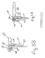
- the liner 30 rests inside the outer shell 22 of a diaphragm tank (Figure 3A).
- the liner 30 includes a raised portion 32 that defines an annular groove.34.
- An o-ring 36 disposed in groove 34 provides a seal preventing fluidic communication between an expandable bladder defined by liner 30 and diaphragm 26 and the space between liner 30 and outer shell 22.
- groove 34 is omitted ( Figure 3B).
- raised portion 32 presents a relief surface 32a, e.g., a surface elevated with respect to the neighboring portion of liner 30, on which o-ring 36 rests.
- the raised portion 32 defines an annulus that accommodates passage fitting 40.
- Liner 30 is easily fabricated by injection molding, although alternative manufacturing techniques may be used. Exemplary materials for liner 30 include polypropylene, teflon, nylon, polyalkylene terephthalate, polyformaldehyde, polystyrene, poly(methyl methacrylate), polycarbonate, and poly(hexylisocyanate).
- An exemplary connector for use with an embodiment of the present invention comprises a passage fitting 40, an o-ring 42 and an annular holder 44 (Figure 4).
- the passage fitting 40 extends through the outer shell 22 and liner 30 of the diaphragm tank.
- Passage fitting 40 may include a thread 46 that extends out from the tank to connect with a hose, pipe or other plumbing.
- the thread may also be tapped on the interior of passage fitting 40, or two threads may be included to provide flexibility in installation.
- the other end of passage fitting 40 defmes a neck 48 having an outer diameter smaller than the remainder of passage fitting 40.
- a shoulder 50 at the inside extent of the thread 46 abuts the outer shell 22 of the diaphragm tank.
- a concave annular groove 52 in the holder 44 retains o-ring 42 in groove 34. To promote a watertight seal, the depth of groove 34 is less than the thickness of the o-ring 42.
- the neck 48 of passage fitting 40 is first inserted through the hole defined by the outer shell 22, gasket 28 and liner 30.
- O-ring 42 and holder 44 are sequentially mounted on neck 48.
- Neck 48 is then bent around holder 44.
- the bent neck 48 presses against the holder 44 to firmly retain the holder 44 in place.
- the shell 22, gasket 28 and liner 30 are tightly clamped between shoulder 50 of passage fitting 40 and holder 44.
- the o-ring 42 will be deformed to expand against the outside of passage fitting 40 as it is squeezed between the holder 44 and the liner 30, providing a watertight seal. This forms a watertight seal at the, junction of the liner 30 and passage fitting 40,
- liner 30 will be squeezed by the holder 44 to fully engage gasket 28, preventing leakage around the gasket.
Landscapes
- Engineering & Computer Science (AREA)
- Physics & Mathematics (AREA)
- Thermal Sciences (AREA)
- Chemical & Material Sciences (AREA)
- Combustion & Propulsion (AREA)
- Mechanical Engineering (AREA)
- General Engineering & Computer Science (AREA)
- Diaphragms And Bellows (AREA)
- Feeding And Controlling Fuel (AREA)
- Closures For Containers (AREA)
Applications Claiming Priority (4)
| Application Number | Priority Date | Filing Date | Title |
|---|---|---|---|
| US6402 | 1993-01-21 | ||
| US773985 | 2004-02-06 | ||
| US10/773,985 US20080128439A1 (en) | 2004-02-06 | 2004-02-06 | Sealing mechanism for diaphragm tank |
| US11/006,402 US7363944B2 (en) | 2004-02-06 | 2004-12-06 | Sealing mechanism for diaphragm tank |
Publications (2)
| Publication Number | Publication Date |
|---|---|
| EP1561999A2 true EP1561999A2 (de) | 2005-08-10 |
| EP1561999A3 EP1561999A3 (de) | 2006-05-03 |
Family
ID=34680823
Family Applications (1)
| Application Number | Title | Priority Date | Filing Date |
|---|---|---|---|
| EP05002435A Withdrawn EP1561999A3 (de) | 2004-02-06 | 2005-02-04 | Dichtungsvorrichtung für Membrangefäss |
Country Status (1)
| Country | Link |
|---|---|
| EP (1) | EP1561999A3 (de) |
Cited By (1)
| Publication number | Priority date | Publication date | Assignee | Title |
|---|---|---|---|---|
| WO2008141374A1 (en) * | 2007-05-18 | 2008-11-27 | Bluescope Steel Limited | Fittings for water storage tank |
Family Cites Families (6)
| Publication number | Priority date | Publication date | Assignee | Title |
|---|---|---|---|---|
| BE626207A (de) * | 1961-12-29 | |||
| FR1422967A (fr) * | 1964-11-16 | 1966-01-03 | Olaer Patent Co | Perfectionnements aux moyens d'accrochage de corps souples ou élastiques pour capacités destinées à être mises sous pression |
| GB1161321A (en) * | 1966-07-20 | 1969-08-13 | Greer Hydraulics Inc | Improvements in Pressure Vessels |
| CH665884A5 (en) * | 1984-10-31 | 1988-06-15 | Stuecklin & Cie Ag | Expansion-accommodating pressure vessel for liq. - has inner container of flexible material filed with gas |
| IT225501Y1 (it) * | 1991-10-02 | 1996-11-18 | Varem Spa | Serbatoio a membrana perfezionato per impianti idraulici |
| DE10230742A1 (de) * | 2002-07-09 | 2004-01-29 | Hydac Technology Gmbh | Hydrospeicher, insbesondere Blasenspeicher |
-
2005
- 2005-02-04 EP EP05002435A patent/EP1561999A3/de not_active Withdrawn
Cited By (1)
| Publication number | Priority date | Publication date | Assignee | Title |
|---|---|---|---|---|
| WO2008141374A1 (en) * | 2007-05-18 | 2008-11-27 | Bluescope Steel Limited | Fittings for water storage tank |
Also Published As
| Publication number | Publication date |
|---|---|
| EP1561999A3 (de) | 2006-05-03 |
Similar Documents
| Publication | Publication Date | Title |
|---|---|---|
| US20080230134A1 (en) | Sealing mechanism for diaphragm tank | |
| US7303091B2 (en) | Expansion tank with double diaphragm | |
| US6418969B1 (en) | In-line thermal expansion tank | |
| CA2628029A1 (en) | Faucet spout with water isolating couplings | |
| EP1519091A3 (de) | Schlauchquetschventil | |
| EP1561999A2 (de) | Dichtungsvorrichtung für Membrangefäss | |
| US20070257218A1 (en) | Backflow-Preventer | |
| CN115210672B (zh) | 减压器 | |
| US11261589B2 (en) | Check valve and a method for controlling a flow of fluid by fluid pressure | |
| EP2065621A3 (de) | Flüssigkeitsfilter für Automatikgetriebe und Verfahren zu dessen Einbau | |
| MX2007004296A (es) | Tanque de expansion con doble diafragma. | |
| US20080115843A1 (en) | Negative check valve of a pneumatic transfer pipe | |
| CA2948818C (en) | Vacuum breaker | |
| JP4754195B2 (ja) | ボール逆止弁とこれを用いた排水制御装置 | |
| US6523568B1 (en) | Combination air vent/probe port and method of constructing same | |
| CN217714094U (zh) | 排水接头组件 | |
| CN100430655C (zh) | 具有双隔膜的膨胀水箱 | |
| CN212078132U (zh) | 一种管路阻隔器 | |
| JPH0643428U (ja) | 自動開閉バルブ | |
| KR100345244B1 (ko) | 원환체를 이용한 체크 밸브 | |
| JP2007132441A (ja) | 逆流防止弁 | |
| JP2004278803A (ja) | 樹脂製ボール逆止め弁とこれを用いたマンホールポンプユニット | |
| JP2005291357A (ja) | ボール逆止弁の配管構造 | |
| CN102439235A (zh) | 射流调节器 | |
| HK1090411B (en) | Expansion tank with double diaphragm |
Legal Events
| Date | Code | Title | Description |
|---|---|---|---|
| PUAI | Public reference made under article 153(3) epc to a published international application that has entered the european phase |
Free format text: ORIGINAL CODE: 0009012 |
|
| AK | Designated contracting states |
Kind code of ref document: A2 Designated state(s): AT BE BG CH CY CZ DE DK EE ES FI FR GB GR HU IE IS IT LI LT LU MC NL PL PT RO SE SI SK TR |
|
| AX | Request for extension of the european patent |
Extension state: AL BA HR LV MK YU |
|
| PUAL | Search report despatched |
Free format text: ORIGINAL CODE: 0009013 |
|
| AK | Designated contracting states |
Kind code of ref document: A3 Designated state(s): AT BE BG CH CY CZ DE DK EE ES FI FR GB GR HU IE IS IT LI LT LU MC NL PL PT RO SE SI SK TR |
|
| AX | Request for extension of the european patent |
Extension state: AL BA HR LV MK YU |
|
| AKX | Designation fees paid | ||
| STAA | Information on the status of an ep patent application or granted ep patent |
Free format text: STATUS: THE APPLICATION IS DEEMED TO BE WITHDRAWN |
|
| 18D | Application deemed to be withdrawn |
Effective date: 20061104 |
|
| REG | Reference to a national code |
Ref country code: DE Ref legal event code: 8566 |